Page 1794 of 2100
8A±18LIGHTING SYSTEM
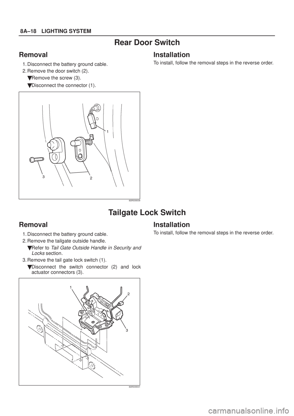
Rear Door Switch
Removal
1. Disconnect the battery ground cable.
2. Remove the door switch (2).
�Remove the screw (3).
�Disconnect the connector (1).
825R200039
Installation
To install, follow the removal steps in the reverse order.
Tailgate Lock Switch
Removal
1. Disconnect the battery ground cable.
2. Remove the tailgate outside handle.
�Refer to
Tail Gate Outside Handle in Security and
Locks
section.
3. Remove the tail gate lock switch (1).
�Disconnect the switch connector (2) and lock
actuator connectors (3).
825R200031
Installation
To install, follow the removal steps in the reverse order.
Page 1795 of 2100
LIGHTING SYSTEM8A±19
Key Remind Switch (Starter Switch)
Removal and Installation
Refer to Lock Cylinder in Steering section.
Hazard Warning Light Switch
Removal
1. Disconnect the battery ground cable.
2. Remove the center cluster assembly (1).
�Refer to
Instrument Panel Assembly in Body
Structure
section.
3. Remove the hazard warning switch (2).
�Disconnect the switch connector.
�To remove the switch, push the lock from the back
side of the center cluster assembly.
825R200026
Installation
To install, follow the removal steps in the reverse order.
Page 1796 of 2100
8A±20LIGHTING SYSTEM
Stoplight Switch
Removal and Installation
Refer to Stoplight Switch in Brake section.
Turn Signal Light Switch (Combination Switch)
Removal and Installation
Refer to Combination Switch in Steering section.
Illumination Controller
Removal
1. Disconnect the battery ground cable.
2. Remove the meter cluster panel cover assembly (2).
�Refer to
Instrument Panel Assembly in Body
Structure
section.
3. Remove the illumination controller (1).
�Disconnect the controller connector.
�Remove the controller knob (4).
�Remove the nut (3).
�Remove the controller from the back side of the
meter cluster panel assembly.
825R200027
Installation
To install, follow the removal steps in the reverse order.
Page 1800 of 2100

8B±2WIPER/WASHER SYSTEM
Windshield Wiper/Washer System
General Description
The circuit consists of the starter switch, windshield wiper
& washer switch, windshield wiper motor, windshield
washer motor and alarm & relay control unit.
When the windshield wiper & washer switch is turned on
with the starter switch on, the battery voltage is applied to
the wiper motor to activate the wiper.
The washer motor squirts glass cleaning fluid while the
washer switch is being pushed. The alarm & relay control
unit relay is used to control motion of the wiper.
Windshield Wiper And Washer Switch
Removal and Installation
Refer to Combination Switch in Steering section.
Windshield Wiper Motor
Removal
1. Disconnect the battery ground cable.
2. Disconnect the connector(2).
3. Remove 4 mounting bolts.
4. Remove the nut of the wiper motor shaft, and
disconnect the linkage.
5. Remove the windshield wiper motor(1).
CAUTION: To facilitate the removal of the nuts, be
sure to put out the tip portion of the linkage
sufficiently through the mounting hole of the motor
by sliding the linkage slowly.
880RW002
Installation
To install, follow the removal steps in the reverse order,
noting the following points:
1. Tighten the wiper motor shaft nut to the specified
torque.
Torque: 14 N´m (122 lb in)
2. Remove the wiper arms on both sides, and rotate the
wiper motor until it gets to the autostop position to
secure windshield wiper correct operation.
Page 1801 of 2100
WIPER/WASHER SYSTEM8B±3
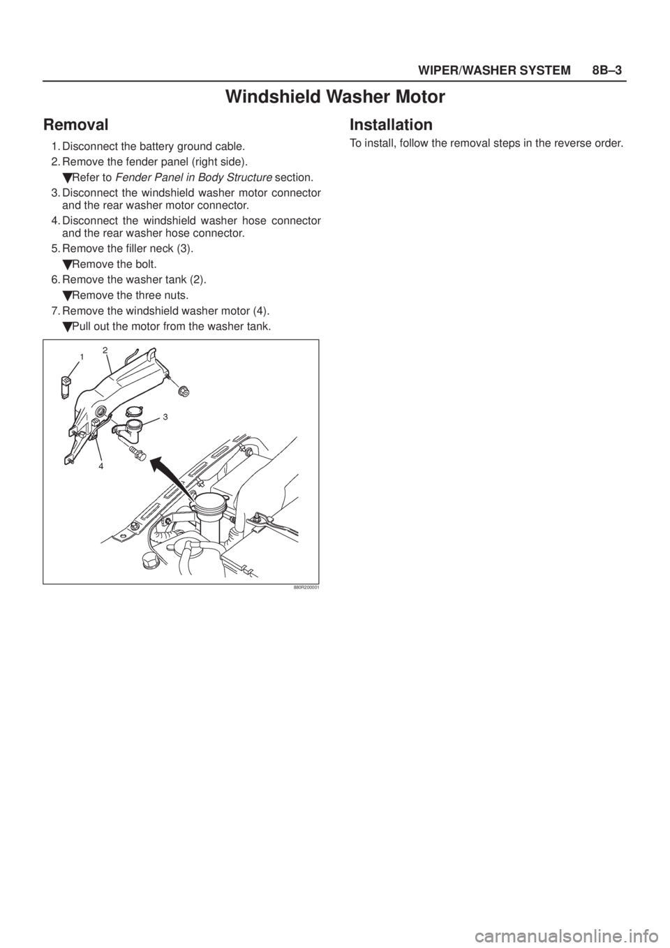
Windshield Washer Motor
Removal
1. Disconnect the battery ground cable.
2. Remove the fender panel (right side).
�Refer to
Fender Panel in Body Structure section.
3. Disconnect the windshield washer motor connector
and the rear washer motor connector.
4. Disconnect the windshield washer hose connector
and the rear washer hose connector.
5. Remove the filler neck (3).
�Remove the bolt.
6. Remove the washer tank (2).
�Remove the three nuts.
7. Remove the windshield washer motor (4).
�Pull out the motor from the washer tank.
880R200001
Installation
To install, follow the removal steps in the reverse order.
Page 1803 of 2100
WIPER/WASHER SYSTEM8B±5
Windshield Wiper Linkage
Windshield Wiper Linkage and Associated Parts
880RW004
Legend
(1) Windshield Wiper Arm/Blade
(2) Vent Cowl Cover(3) Windshield Wiper Linkage Assembly
(4) Windshield Wiper Motor
Removal
1. Disconnect the battery ground cable.
2. Remove the windshield wiper arm/blade.
3. Remove the vent cowl cover.
4. Remove the windshield wiper motor.
5. Remove the pivot assembly mounting nuts.
6. Take out the windshield wiper linkage assembly from
the opening of the cowl.
Installation
To install, follow the removal steps in the reverse order.
Page 1806 of 2100

8B±8WIPER/WASHER SYSTEM
Rear Wiper/Washer System
General Description
The circuit consists of the starter switch, rear wiper &
washer switch, rear wiper motor, rear washer motor and
Alarm & relay control unit.
When the rear wiper & washer switch is turned on with the
starter switch on, the battery voltage is applied to the
wiper motor to activate the wiper.
The washer motor squirts glass cleaning fluid while the
washer switch is being pushed. The alarm & relay control
unit is used to control motion of the wiper.
Rear Wiper and Washer Switch
Removal
1. Disconnect the battery ground cable.
2. Remove the dash side trim panel(1).
3. Remove the lower cover assembly(2).
821RW254±1
4. Remove the rear wiper & washer switch (4).
�Disconnect the connector.
�Push the lock from the back side of the lower cover
assembly (3).
825R200028
Installation
To install, follow the removal steps in the reverse order,
noting the following point:
1. Push the switch with your fingers until it locks
securely.
Page 1807 of 2100
WIPER/WASHER SYSTEM8B±9
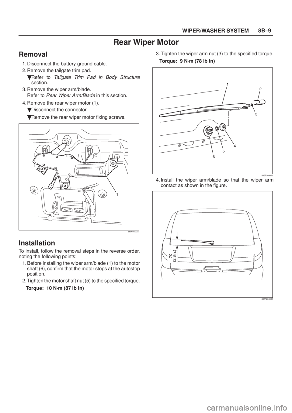
Rear Wiper Motor
Removal
1. Disconnect the battery ground cable.
2. Remove the tailgate trim pad.
�Refer to
Tailgate Trim Pad in Body Structure
section.
3. Remove the wiper arm/blade.
Refer to
Rear Wiper Arm/Blade in this section.
4. Remove the rear wiper motor (1).
�Disconnect the connector.
�Remove the rear wiper motor fixing screws.
885R200002
Installation
To install, follow the removal steps in the reverse order,
noting the following points:
1. Before installing the wiper arm/blade (1) to the motor
shaft (6), confirm that the motor stops at the autostop
position.
2. Tighten the motor shaft nut (5) to the specified torque.
Torque: 10 N´m (87 lb in)3. Tighten the wiper arm nut (3) to the specified torque.
Torque: 9 N´m (78 lb in)
885R200001
4. Install the wiper arm/blade so that the wiper arm
contact as shown in the figure.
885R200005

Removal and Installation
Refer to Lock Cylinder in Steering section.
Hazard Warning Light Switch
Removal
1. Disconnect the battery ground cable")

Removal and Installation
Refer to Combination")
 Windshield Wiper Arm/Blade
(2) Vent Cowl Cover(3) Windshield Wiper Linkage Assembly")