Page 1762 of 2100
7A1±75
DTC P1850 Brake Band Apply Solenoid Malfunction
D07R200010
Circuit Description
�The brake band apply solenoid is a normally open
solenoid which controls th")
TRANSMISSION CONTROL SYSTEM (4L30±E)7A1±75
DTC P1850 Brake Band Apply Solenoid Malfunction
D07R200010
Circuit Description
�The brake band apply solenoid is a normally open
solenoid which controls the flow of fluid for brake band
application. The Powertrain Control Module (PCM)
uses Pulse Width Modulation (PWM) and changes
the duty cycle to control the solenoid. The PCM turns
the solenoid on (energized) and off (deenergized) at a
constant frequency. The length of time the solenoid is
energized during each on/off cycle is called the pulse
width. By varying or ªmodulatingº the pulse width, the
solenoid output pressure is changed. Since the
solenoid is normally open, increasing the pulse width
increases the duty cycle and decreases the output
pressure. PWM control provides smooth band
application without an accumulator. The band is only
applied in first and second gears.
�In the event of an electrical failure (open), the
solenoid regulates at the maximum oil flow (0% duty
cycle).
�The solenoid is activated by a current. This current is
produced by applying a voltage to one side (the High
side) and a ground to the other side (Low side).
�The High Side Driver (HSD) is a circuit of the PCM
that acts as a switch between the solenoids and the
supply voltage. The High side of the solenoid is
permanently supplied with voltage. When the ignition
is off, the HSD is turned off.This DTC detects a continuous open or short to ground in
the brake band apply solenoid circuit or the brake band
apply solenoid. This is a type ªDº DTC.
Conditions For Setting The DTC
�Battery voltage is between 10 and 16 volts.
�Ignition is ªonº, Engine ªrunº.
�The PCM commands the solenoid ªonº and the
voltage remains high (B+), or the PCM commands
the solenoid ªoffº and the voltage remains low (zero
volts).
�All conditions met in 1.34 ~ 1.56 seconds.
Action Taken When The DTC Sets
�Inhibit brake band apply solenoid.
�The PCM will not illuminate the Malfunction Indicator
Lamp (MIL).
Conditions For Clearing The DTC
�The DTC can be cleared from the PCM history by
using a scan tool.
�The DTC will be cleared from history when the vehicle
has achieved 40 warmup cycles without a failure
reported.
�The PCM will cancel the DTC default actions when
the fault no longer exists and the ignition is cycled ªoffº
long enough to power down the PCM.
Page 1766 of 2100
7A1±79
DTC P1860 TCC PWM Solenoid Electrical
D07R200011
Circuit Description
The PCM allows current to flow through the solenoid coil
according to the duty cycle (")
TRANSMISSION CONTROL SYSTEM (4L30±E)7A1±79
DTC P1860 TCC PWM Solenoid Electrical
D07R200011
Circuit Description
The PCM allows current to flow through the solenoid coil
according to the duty cycle (percentage of ªonº and ªoffº
time). This current flow through the solenoid coil creates
a magnetic field that magnetizes the solid core. The
magnetized core attracts the check ball to seat against
spring pressure. This blocks the exhaust for the TCC
signal fluid and allows 2±3 drive fluid to feed to TCC signal
circuit.The TCC signal fluid pressure acts on the TCC
regulator valve to regulate line pressure and to apply fluid
pressure to the torque converter clutch shift control valve.
When the TCC shift valve is in the apply position,
regulated apply fluid pressure is directed through the TCC
valve to apply the torque converter clutch. The TCC
PWM solenoid is used in conjunction with the TCC PWM
solenoid to regulate fluid to the torque converter. The
TCC PWM solenoid is attached to the valve body within
the transmission.
This DTC detects a continuous open or short to ground or
ignition in the TCC circuit or the TCC PWM solenoid. This
is a type ªBº DTC.
Conditions For Setting The DTC
�Battery voltage is between 10 and 16 volts.
�No shift solenoid A DTCs P0751 or P0752 or P0753.
�No shift solenoid B DTCs P0756 or P0757 or P0758.
�Ignition is ªonº, Engine ªrunº.
�The PCM commands the solenoid ªonº and the
voltage remains low (zero volts).
�The PCM commands the solenoid ªoffº and the
voltage remains high (B+).
�All conditions met for 0.875 ~ 1.25 seconds.
Action Taken When The DTC Sets
�Inhibit TCC engagement.�For lamp illuminate refer to
DTC type definition (type
B).
Conditions For Clearing The MIL/DTC
�The PCM will turn off the MIL and CHECK TRANS
Lamp after three consecutive ignition cycles without a
failure reported.
�The DTC can be cleared from the PCM history by
using a scan tool.
�The DTC will be cleared from history when the vehicle
has achieved 40 warmup cycles without a failure
reported.
�The PCM will cancel the DTC default actions when
the fault no longer exists and the ignition is cycled ªoffº
long enough to power down the PCM.
Diagnostic Aids
�Inspect the wiring for poor electrical connections at
the PCM and at the transmission connector. Look for
possible bent, backed out, deformed or damaged
terminals. Check for weak terminal tension as well.
Also check for a chafed wire that could short to bare
metal or other wiring. Inspect for a broken wire inside
the insulation.
�When diagnosing for a possible intermittent short or
open condition, move the wiring harness while
observing test equipment for a change.
Test Description
The numbers below refer to the step numbers on the
diagnostic chart
:
3. This test checks for voltage to the solenoid.
4. This test checks the ability of the PCM and wiring to
control the ignition circuit.
9. This test checks the resistance of the TCC solenoid
and the internal wiring harness.
Page 1779 of 2100
LIGHTING SYSTEM8A±3
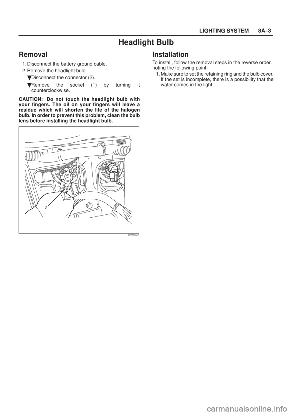
Headlight Bulb
Removal
1. Disconnect the battery ground cable.
2. Remove the headlight bulb.
�Disconnect the connector (2).
�Remove the socket (1) by turning it
counterclockwise.
CAUTION: Do not touch the headlight bulb with
your fingers. The oil on your fingers will leave a
residue which will shorten the life of the halogen
bulb. In order to prevent this problem, clean the bulb
lens before installing the headlight bulb.
801R200021
Installation
To install, follow the removal steps in the reverse order.
noting the following point:
1. Make sure to set the retaining ring and the bulb cover.
If the set is incomplete, there is a possibility that the
water comes in the light.
Page 1780 of 2100
.
�Remove the screw.
�Disconnect the connector.
3. Remove the headlight")
8A±4LIGHTING SYSTEM
Headlight Assembly
Removal
1. Disconnect the battery ground cable.
2. Remove the front combination light (2).
�Remove the screw.
�Disconnect the connector.
3. Remove the headlight assembly (1).
�Disconnect the connector.
�Remove four screws.
801R200022
Installation
To install, follow the removal steps in the reverse order.
noting the following point:
1. After installing the headlight, be sure to adjust the
headlight aim.
Headlight Adjustment
Preparation
Place the vehicle with 1 person in driver seat on a level
surface and check to see if the inflation pressure of the
tires is correct, the lenses are clean, the battery is
sufficiently charged, and adjust to place vehicle by using
the screen.1. Set a vertical screen on a level surface.
2. Toward the screen (1) from the bulb center mark of
the headlight, extend parallel lines to the floor. Mark
point (A) and (B) on the screen at the intersection of
parallel line and the screen.
3. Draw vertical lines through point (A) and (B) on the
screen.
801R200019
4. Keep the vehicle (2) 3m (9.8 ft) apart from the screen
(1).
5. Draw a horizontal line through point (A) and (B) on the
screen (1).
801R200009
Page 1782 of 2100
8A±6LIGHTING SYSTEM
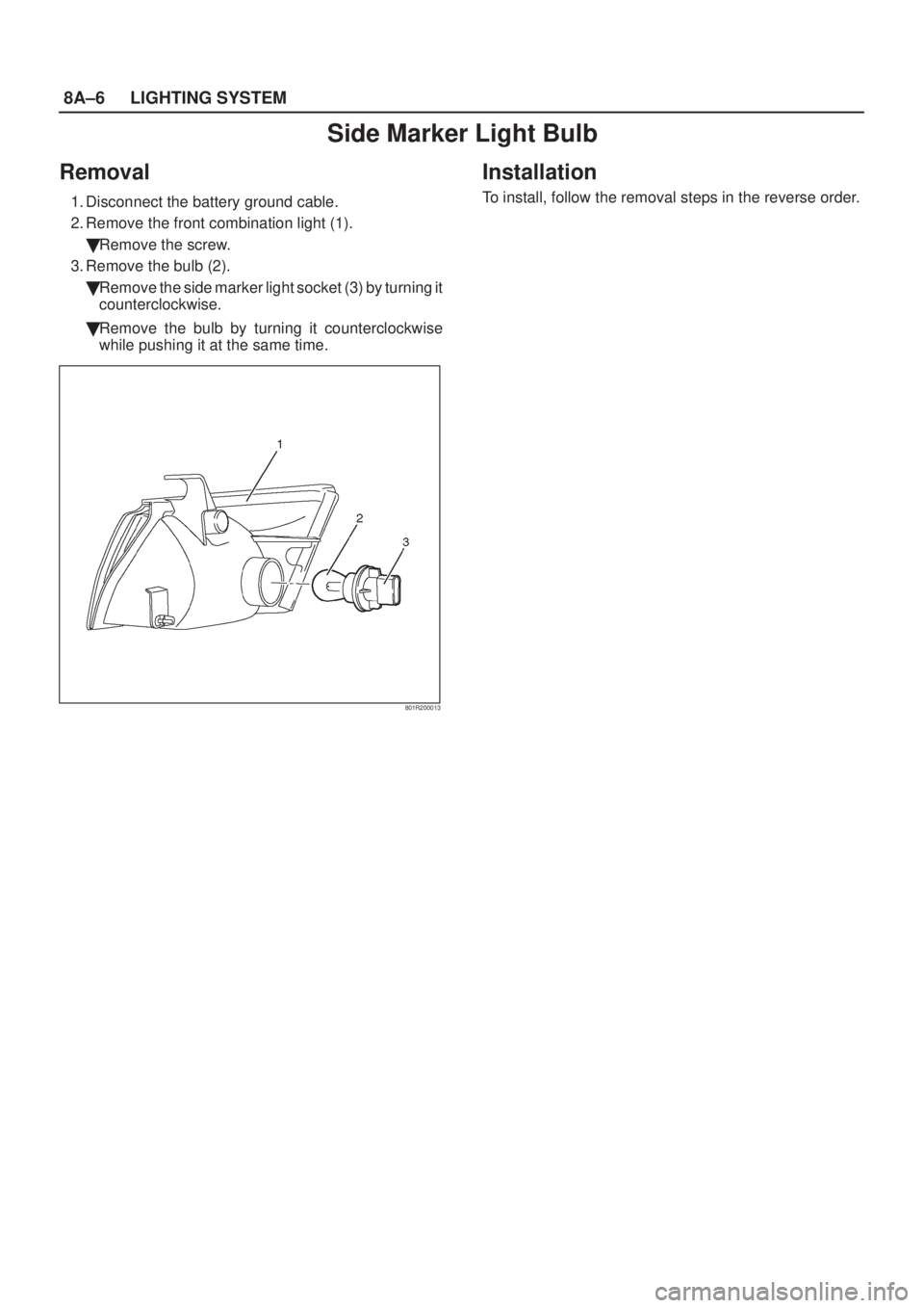
Side Marker Light Bulb
Removal
1. Disconnect the battery ground cable.
2. Remove the front combination light (1).
�Remove the screw.
3. Remove the bulb (2).
�Remove the side marker light socket (3) by turning it
counterclockwise.
�Remove the bulb by turning it counterclockwise
while pushing it at the same time.
801R200013
Installation
To install, follow the removal steps in the reverse order.
Page 1783 of 2100
LIGHTING SYSTEM8A±7
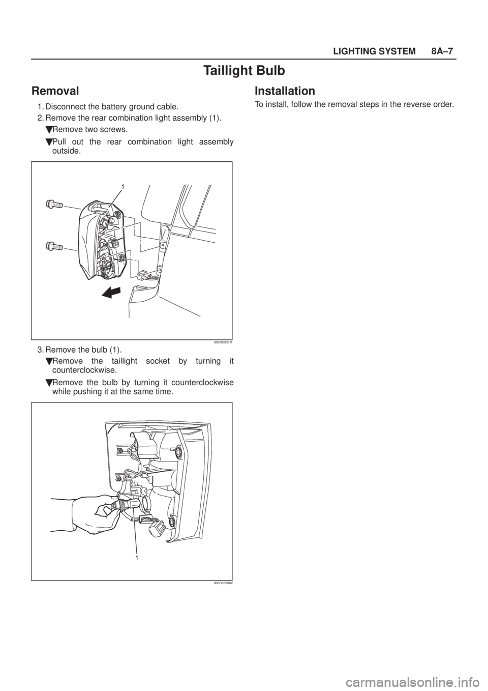
Taillight Bulb
Removal
1. Disconnect the battery ground cable.
2. Remove the rear combination light assembly (1).
�Remove two screws.
�Pull out the rear combination light assembly
outside.
803R200011
3. Remove the bulb (1).
�Remove the taillight socket by turning it
counterclockwise.
�Remove the bulb by turning it counterclockwise
while pushing it at the same time.
803R200002
Installation
To install, follow the removal steps in the reverse order.
Page 1784 of 2100
8A±8LIGHTING SYSTEM
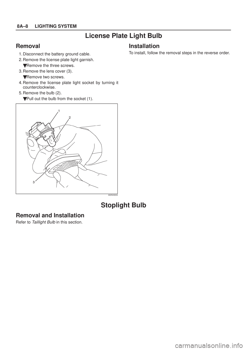
License Plate Light Bulb
Removal
1. Disconnect the battery ground cable.
2. Remove the license plate light garnish.
�Remove the three screws.
3. Remove the lens cover (3).
�Remove two screws.
4. Remove the license plate light socket by turning it
counterclockwise.
5. Remove the bulb (2).
�Pull out the bulb from the socket (1).
803R200003
Installation
To install, follow the removal steps in the reverse order.
Stoplight Bulb
Removal and Installation
Refer to Taillight Bulb in this section.
Page 1785 of 2100
LIGHTING SYSTEM8A±9
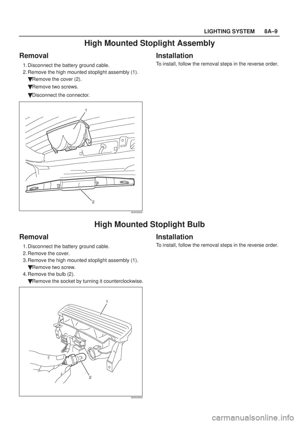
High Mounted Stoplight Assembly
Removal
1. Disconnect the battery ground cable.
2. Remove the high mounted stoplight assembly (1).
�Remove the cover (2).
�Remove two screws.
�Disconnect the connector.
803R200004
Installation
To install, follow the removal steps in the reverse order.
High Mounted Stoplight Bulb
Removal
1. Disconnect the battery ground cable.
2. Remove the cover.
3. Remove the high mounted stoplight assembly (1).
�Remove two screw.
4. Remove the bulb (2).
�Remove the socket by turning it counterclockwise.
803R200005
Installation
To install, follow the removal steps in the reverse order.