Page 1819 of 2100
ENTERTAINMENT8C±7
Installation
To install, follow the removal steps in the reverse order.
Rear Tweeter Assembly
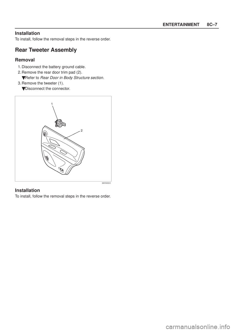
Removal
1. Disconnect the battery ground cable.
2. Remove the rear door trim pad (2).
�Refer to
Rear Door in Body Structure section.
3. Remove the tweeter (1).
�Disconnect the connector.
890R200031
Installation
To install, follow the removal steps in the reverse order.
Page 1820 of 2100
8C±8ENTERTAINMENT
Horn
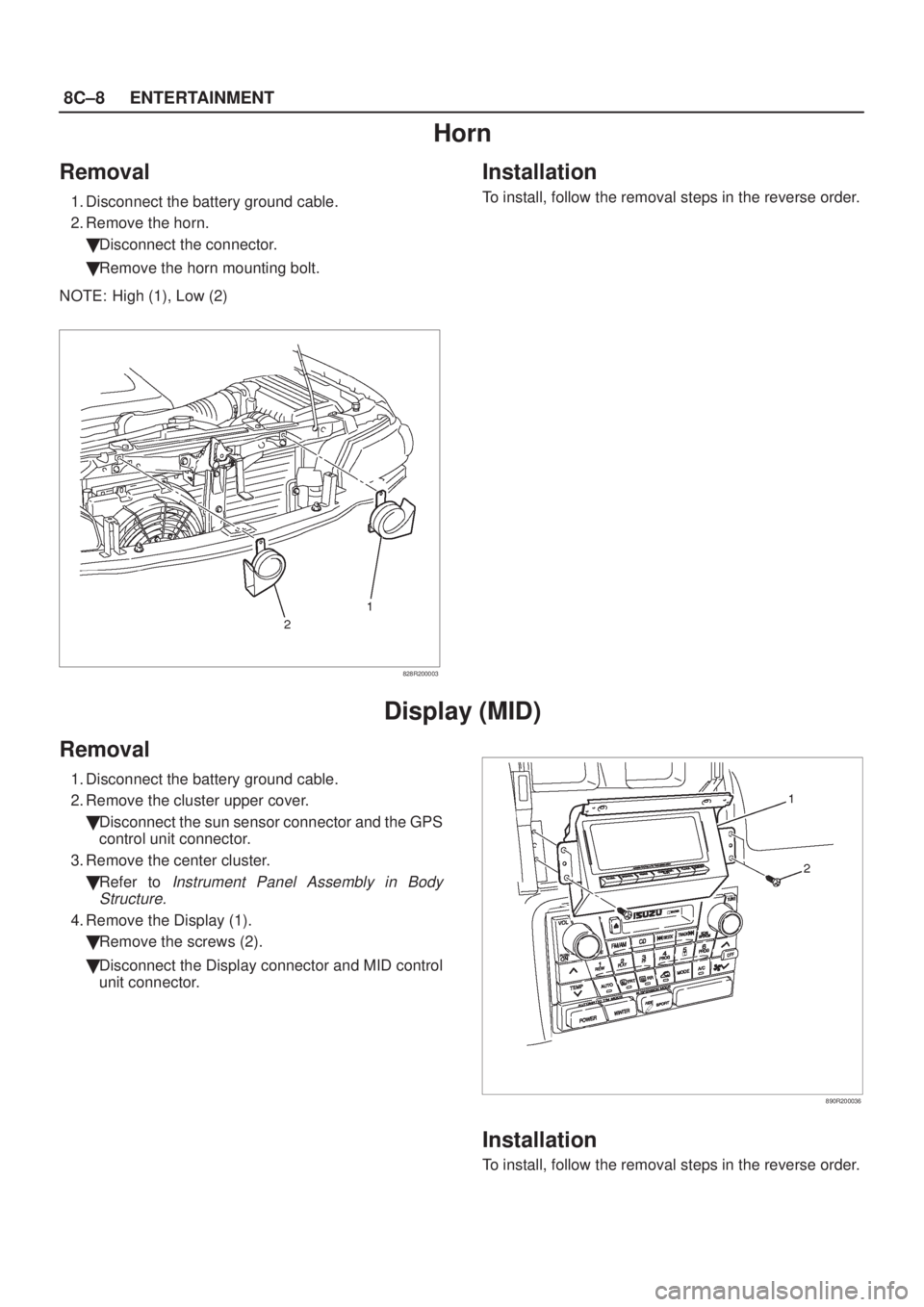
Removal
1. Disconnect the battery ground cable.
2. Remove the horn.
�Disconnect the connector.
�Remove the horn mounting bolt.
NOTE: High (1), Low (2)
828R200003
Installation
To install, follow the removal steps in the reverse order.
Display (MID)
Removal
1. Disconnect the battery ground cable.
2. Remove the cluster upper cover.
�Disconnect the sun sensor connector and the GPS
control unit connector.
3. Remove the center cluster.
�Refer to
Instrument Panel Assembly in Body
Structure.
4. Remove the Display (1).
�Remove the screws (2).
�Disconnect the Display connector and MID control
unit connector.
890R200036
Installation
To install, follow the removal steps in the reverse order.
Page 1821 of 2100
.
�Refer to
MID (1) in this section.
�Remove the control unit (3) from the bracke")
ENTERTAINMENT8C±9
MID Control Unit
Removal
1. Disconnect the battery ground cable.
2. Remove the MID control unit (3).
�Refer to
MID (1) in this section.
�Remove the control unit (3) from the bracket (2).
CAUTION: When the battery is disconnected, the
MID control unit directional data is lost (the control
unit returns to its start-up condition). When the
battery is reconnected, the display will be erroneous
until the control unit receives a clear GPS satellite
signal and resets its directional data.
After reconnecting the battery, wait until the satellite
mark indicator turns on. Select an area where there
are no high buildings or other obstacles to electro-
magnetic waves. Drive the vehicle in a straight line at
a speed exceeding 32 km/h (20 mph) for at least 20 se-
conds.
D08R200055
Installation
To install, follow the removal steps in the reverse order.
CAUTION: When installing the MID control unit,
turn the face with part number (4) stamped on the
MID control unit toward the front of vehicle.
Page 1822 of 2100
8C±10ENTERTAINMENT
GPS Control Unit
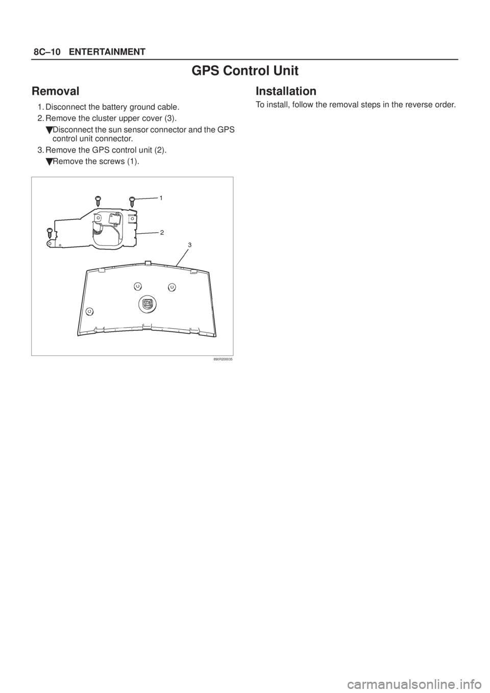
Removal
1. Disconnect the battery ground cable.
2. Remove the cluster upper cover (3).
�Disconnect the sun sensor connector and the GPS
control unit connector.
3. Remove the GPS control unit (2).
�Remove the screws (1).
890R200035
Installation
To install, follow the removal steps in the reverse order.
Page 1830 of 2100
Ye sNo
1Is fuse (AUDIO 20A) normal?ÐGo to Step 2Replace fuse
2Remove connectors at display unit.
Is there battery voltage acros")
8C±18ENTERTAINMENT
Symptom Diagnosis
MID Not Appears
StepActionValue(s)Ye sNo
1Is fuse (AUDIO 20A) normal?ÐGo to Step 2Replace fuse
2Remove connectors at display unit.
Is there battery voltage across terminal No. I-12±16
(display unit harness connector)?
12VGo to Step 4Go to Step 3
3Repair open circuit between terminal No. I-12±16
(display unit harness connector) and the battery.
Is the action complete?
ÐGo to Step 2Ð
4Move the ignition switch to the ACC position.
Is there battery voltage across terminal No. I-12±7
(display unit harness connector)?
12VGo to Step 6Go to Step 5
5Repair open circuit between terminal No. I-12±7
(display unit harness connector) and the battery.
Is the action complete?
ÐGo to Step 4Ð
6Move the starter switch to the IGN position.
Is there battery voltage across terminal No. I-12±14
(display unit harness connector)?
12VGo to Step 8Go to Step 7
7Repair open circuit between terminal No. I-12±14
(display unit harness connector) and the battery.
Is the action complete?
ÐGo to Step 6Ð
8Replace the display unit.
Is the action complete?
ÐGo to Step 1Ð
Page 1831 of 2100
Ye sNo
11. Remove the connectors from the display unit.
2. Turn the ignition switch to the ON position.
Is")
ENTERTAINMENT8C±19
No COMPASS, CLOCK, FUEL CONSUMPTION, or SERVICE Display
StepActionValue(s)Ye sNo
11. Remove the connectors from the display unit.
2. Turn the ignition switch to the ON position.
Is there approximately 5 volts across terminal No.
I-12±1 (display unit harness connector)?
5VGo to Step 2Go to Step 5
2Remove the connectors form the display unit.
Is there battery voltage between the No. I-12±7
terminal and the No. I-12±16 terminal (display unit
harness connector)?
12VGo to Step 4Go to Step 3
3Repair open circuit between terminal No. I-12±7 and
terminal No. I-12±16.
Is the action complete?
ÐGo to Step 2Ð
4Replace the display unit.
Is the action complete?
ÐGo to Step 1Ð
5Remove the MID connectors.
Is there battery voltage between the No. I-13±7
terminal, the No. I-13±8 terminal, and the No. I-13±16
terminal (display unit harness connector)?
12VGo to Step 7Go to Step 6
6Repair open circuit between terminal No. I-13±7,
terminal No. I-13±8, and terminal No. I-13±16.
Is the action complete?
ÐGo to Step 5Ð
7Replace the MID
Is the action complete?
ÐGo to Step 1Ð
Page 1871 of 2100

METER AND GAUGE8E±5
Connector A
TerminalFunction
1Ð
2Intelligent suspension indicator light
3TOD indicator light ªRearº
4Ð
5TOD indicator light ªAUTOº
6Ð
7TOD indicator light ªFrontº
8A/T shift indicator light ª3º
9A/T shift indicator light ªDº
10A/T shift indicator light ª2º
11SRS ± air bag warning light
12Ground
13Battery
14Stater switch
15A/T oil temperature warning light
16Seat belt indicator light
17Charge warning light
18Ð
19Ð
20Ð
21A/T shift indicator light ªLº
22ABS warning light
23Ð
24Ð
25Reduced power warning light
26Oil pressure warning light
27Check trans warning light
28MIL(check engine) warning light
29Check TOD
30Engine coolant temperature gauge
Connector B
TerminalFunction
1A/T shift indicator light ªRº
2A/T shift indicator light
3A/T shift indicator light ªNº
4A/T shift indicator light ªPº
5Illumination light
6Engine revolution pulse
7Speed sensor pulse
8Turn signal indicator light (LH)
9Brake warning light
10High beam indicator light (+)
11High beam indicator light (±)
12Turn signal indicator light (RH)
13Turn signal indicator light
14Ð
15Illumination light
16Ground
Connector C
TerminalFunction
1Starter switch
2Ð
3Fuel gauge
4Low fuel warning light
5Cruise set indicator light
6Ð
7Ð
8Ð
9Ð
10Sport mode indicator light
11Ð
12Winter drive indicator light
13Power drive indicator light
14Ð
Page 1872 of 2100
8E±6METER AND GAUGE
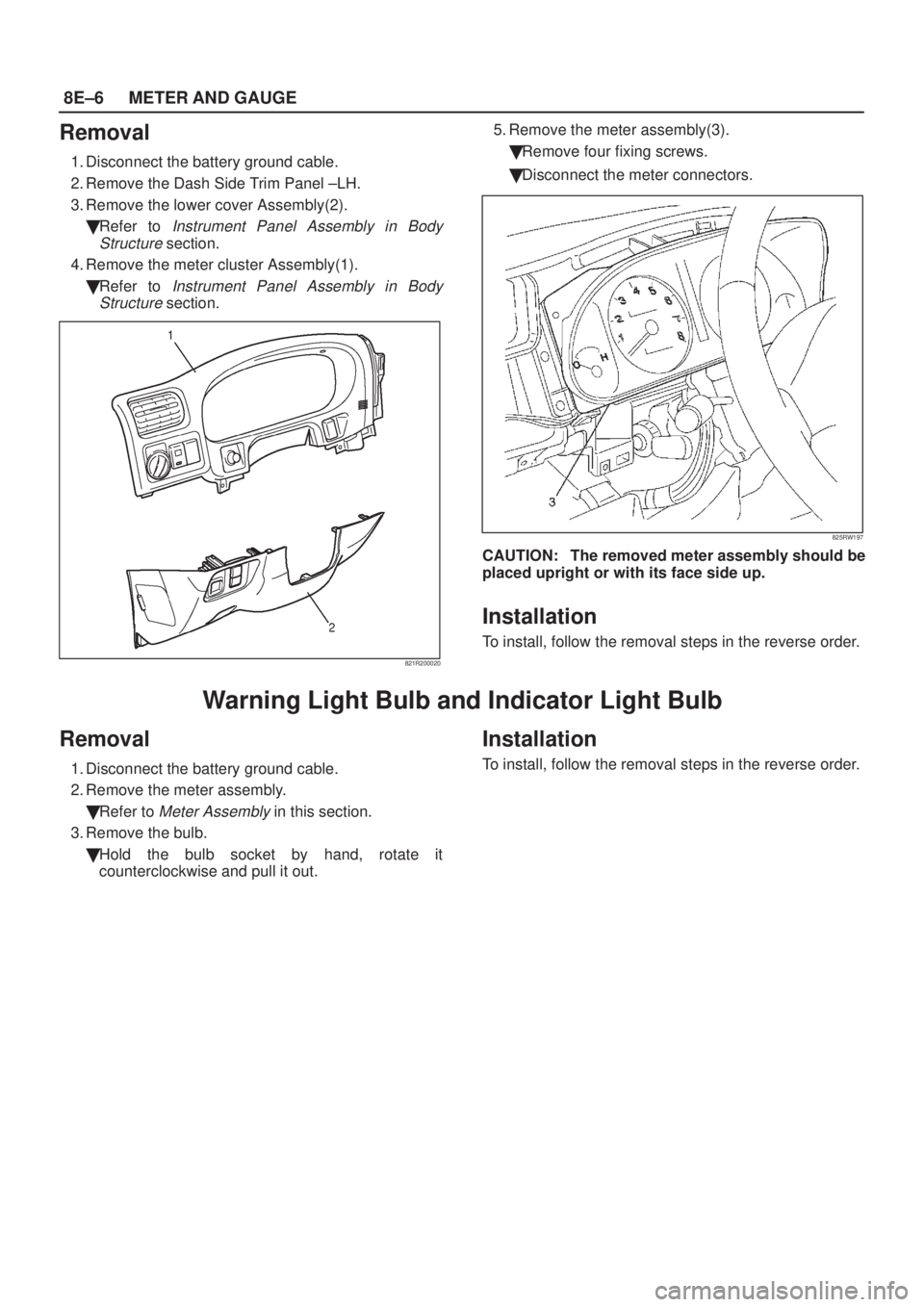
Removal
1. Disconnect the battery ground cable.
2. Remove the Dash Side Trim Panel ±LH.
3. Remove the lower cover Assembly(2).
�Refer to
Instrument Panel Assembly in Body
Structure
section.
4. Remove the meter cluster Assembly(1).
�Refer to
Instrument Panel Assembly in Body
Structure
section.
821R200020
5. Remove the meter assembly(3).
�Remove four fixing screws.
�Disconnect the meter connectors.
825RW197
CAUTION: The removed meter assembly should be
placed upright or with its face side up.
Installation
To install, follow the removal steps in the reverse order.
Warning Light Bulb and Indicator Light Bulb
Removal
1. Disconnect the battery ground cable.
2. Remove the meter assembly.
�Refer to
Meter Assembly in this section.
3. Remove the bulb.
�Hold the bulb socket by hand, rotate it
counterclockwise and pull it out.
Installation
To install, follow the removal steps in the reverse order.