Page 32 of 2100

1A±6
HEATING, VENTILATION AND AIR CONDITIONING (HVAC)
Heater Unit
Heater Unit and Associated Parts
840R200008
Legend
(1) Instrument Panel Assembly
(2) Cross Beam Assembly
(3) Instrument Panel Bracket W/Suspension
Control Unit
(4) Ventilation Lower Duct(5) Rear Heater Duct
(6) Evaporator Assembly
(7) Heater Unit Assembly
(8) Heater Hose
(9) Power Transistor Connector
Removal
1. Disconnect the battery ground cable.
2. Drain the engine coolant.
3. Discharge and recover refrigerant (with air
conditioning).
�Refer to
Refrigerant Recovery in this section.
4. Remove the Instrument panel assembly.
�Refer to
Instrument Panel Assembly in Body and
Accessories section.
5. Remove instrument panel bracket w/suspension
control unit.
�Refer to
Cross Beam Assembly in Body and
Accessories section.
6. Cross Beam Assembly.
�Refer to
Cross Beam Assembly in Body and
Accessories section.
7. Disconnect power transistor connector.
8. Remove evaporator assembly.
�Refer to
Evaporator Assembly in this section.
9. Remove ventilation lower duct.
10. Remove rear heater duct.
�Remove foot rest, carpet and 3 clips.
11. Disconnect mode/mix actuator connector.
12. Remove heater unit assembly.
�Disconnect heater hoses at heater unit.
Installation
To install, follow the removal steps in the reverse order,
noting the following points:
1. When handling the PCM and the control unit, be
careful not to make any improper connection of the
connectors.
Page 42 of 2100
1A±16
HEATING, VENTILATION AND AIR CONDITIONING (HVAC)
Rear Heater Duct, Defroster Nozzle and Ventilation Duct
Rear Heater Duct, Defroster Nozzle, Ventilation Duct and Associated Parts
840R200009
Legend
(1) Defroster Nozzle
(2) Cross Beam Assembly
(3) Center Ventilation Duct and Side Defroster
Duct(4) Instrument Panel Bracket W/Suspension
Control Unit
(5) Instrument Panel Assembly
(6) Rear Heater Duct
(7) Ventilation Lower Duct
Removal
1. Disconnect the battery ground cable.
2. Remove instrument panel assembly.
�Refer to
Instrument Panel Assembly in Body and
Accessories section.
3. Remove center ventilation duct and side defroster
duct.
�Remove 5 screws.4. Remove instrument panel brackets w/suspension
control unit.
�Refer to
Cross Beam Assembly in Body and
Accessories section.
5. Remove cross beam assembly.
�Refer to
Cross Beam Assembly in Body and
Accessories section.
6. Remove ventilation lower duct.
Page 699 of 2100

5C±19 POWER±ASSISTED BRAKE SYSTEM
7. Tighten the steering column fixing nut (9) (Cross
Beam) to the specified torque.
Torque: 17 N´m (12 lb ft)
8. Apply grease to the entire circumference of the Push
rod pin (7).
9. Install push rod pin (7).
10. Install snap pin (4).
11. Connect the anti-theft control module connector.
Refer to
Body and Accessories section in this
manual.12. Connect the stop light switch connector (3).
13. Install driver knee bolster (10) and lower cover (8).
14. Install the engine hood opening lever.
15. Connect the yellow 3 way SRS connector located
under the steering column.
16. Connect the battery ª±º terminal cable.
Stoplight Switch
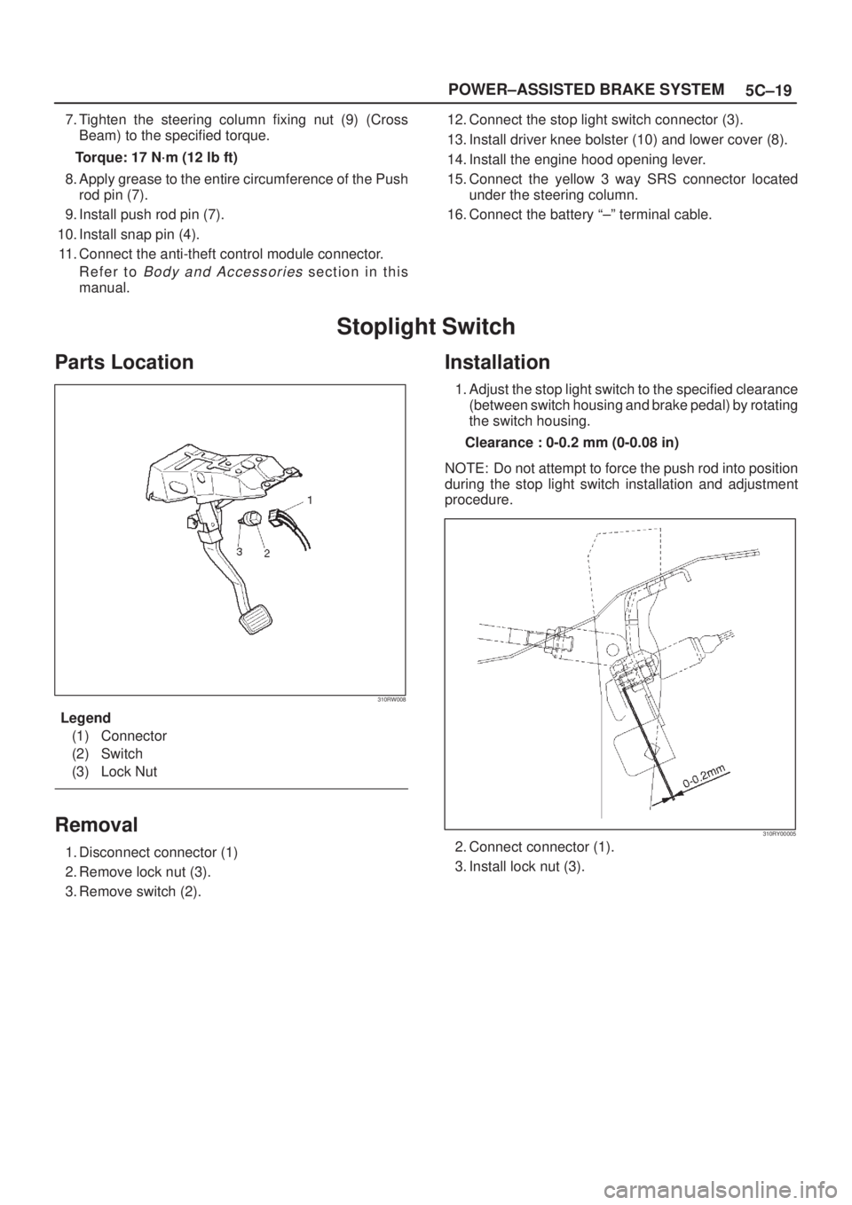
Parts Location
310RW008
Legend
(1) Connector
(2) Switch
(3) Lock Nut
Removal
1. Disconnect connector (1)
2. Remove lock nut (3).
3. Remove switch (2).
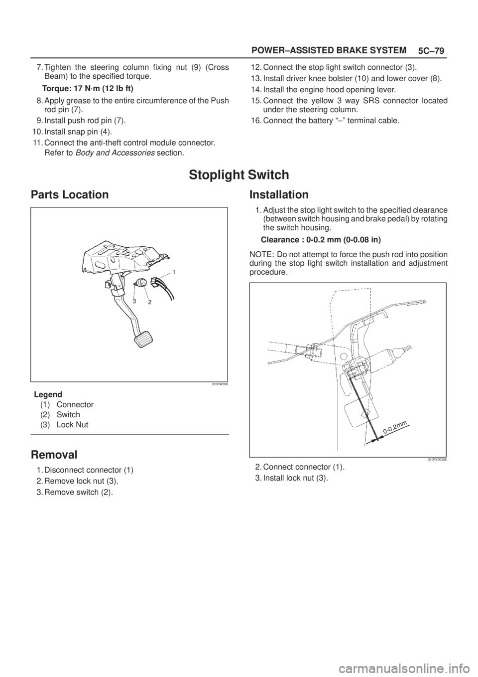
Installation
1. Adjust the stop light switch to the specified clearance
(between switch housing and brake pedal) by rotating
the switch housing.
Clearance : 0-0.2 mm (0-0.08 in)
NOTE: Do not attempt to force the push rod into position
during the stop light switch installation and adjustment
procedure.
310RY00005
2. Connect connector (1).
3. Install lock nut (3).
Page 759 of 2100

5C±79 POWER±ASSISTED BRAKE SYSTEM
7. Tighten the steering column fixing nut (9) (Cross
Beam) to the specified torque.
Torque: 17 N´m (12 lb ft)
8. Apply grease to the entire circumference of the Push
rod pin (7).
9. Install push rod pin (7).
10. Install snap pin (4).
11. Connect the anti-theft control module connector.
Refer to
Body and Accessories section.12. Connect the stop light switch connector (3).
13. Install driver knee bolster (10) and lower cover (8).
14. Install the engine hood opening lever.
15. Connect the yellow 3 way SRS connector located
under the steering column.
16. Connect the battery ª±º terminal cable.
Stoplight Switch
Parts Location
310RW008
Legend
(1) Connector
(2) Switch
(3) Lock Nut
Removal
1. Disconnect connector (1)
2. Remove lock nut (3).
3. Remove switch (2).
Installation
1. Adjust the stop light switch to the specified clearance
(between switch housing and brake pedal) by rotating
the switch housing.
Clearance : 0-0.2 mm (0-0.08 in)
NOTE: Do not attempt to force the push rod into position
during the stop light switch installation and adjustment
procedure.
310RY00005
2. Connect connector (1).
3. Install lock nut (3).
Page 1781 of 2100
LIGHTING SYSTEM8A±5
6. Turn the headlight low beam on.
7. Adjust the CUTLINE 30 mm (1.18 in) below the
horizontal line (H).
801R200011
Vertical Adjustment
Use a screwdriver for vertical adjustment.
801R200012
Page 1798 of 2100

8A±22LIGHTING SYSTEM
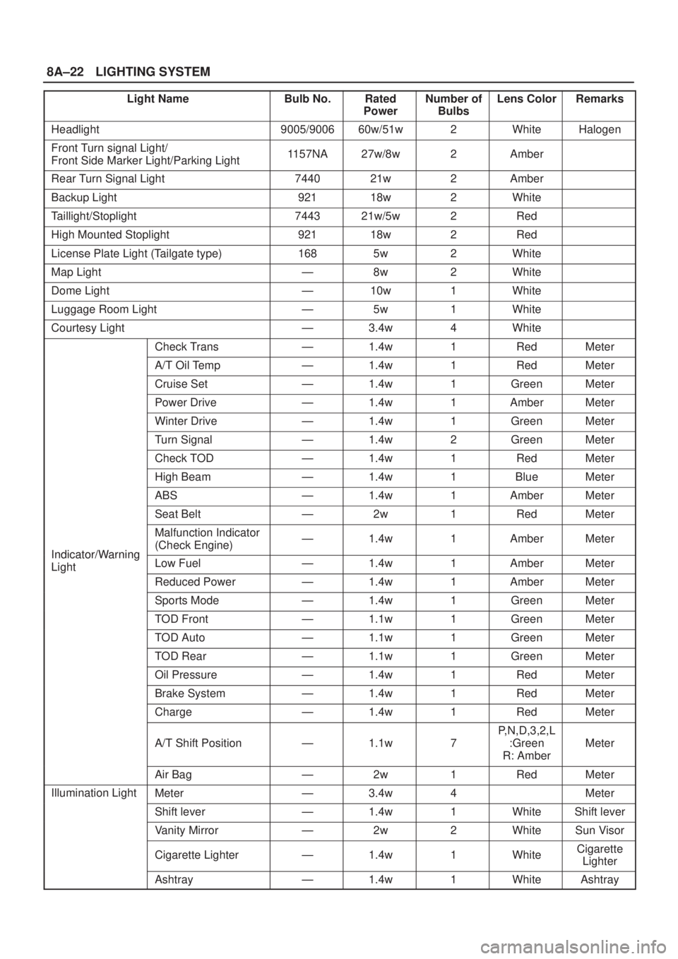
Light NameBulb No.Rated
PowerNumber of
BulbsLens ColorRemarks
Headlight9005/900660w/51w2WhiteHalogen
Front Turn signal Light/
Front Side Marker Light/Parking Light1157NA27w/8w2Amber
Rear Turn Signal Light744021w2Amber
Backup Light92118w2White
Taillight/Stoplight744321w/5w2Red
High Mounted Stoplight92118w2Red
License Plate Light (Tailgate type)1685w2White
Map LightÐ8w2White
Dome LightÐ10w1White
Luggage Room LightÐ5w1White
Courtesy LightÐ3.4w4White
Check TransÐ1.4w1RedMeter
A/T Oil TempÐ1.4w1RedMeter
Cruise SetÐ1.4w1GreenMeter
Power DriveÐ1.4w1AmberMeter
Winter DriveÐ1.4w1GreenMeter
Turn SignalÐ1.4w2GreenMeter
Check TODÐ1.4w1RedMeter
High BeamÐ1.4w1BlueMeter
ABSÐ1.4w1AmberMeter
Seat BeltÐ2w1RedMeter
Indicator/Warning
Malfunction Indicator
(Check Engine)Ð1.4w1AmberMeter
Indicator/Warning
LightLow FuelÐ1.4w1AmberMeterg
Reduced PowerÐ1.4w1AmberMeter
Sports ModeÐ1.4w1GreenMeter
TOD FrontÐ1.1w1GreenMeter
TOD AutoÐ1.1w1GreenMeter
TOD RearÐ1.1w1GreenMeter
Oil PressureÐ1.4w1RedMeter
Brake SystemÐ1.4w1RedMeter
ChargeÐ1.4w1RedMeter
A/T Shift PositionÐ1.1w7
P,N,D,3,2,L
:Green
R: Amber
Meter
Air BagÐ2w1RedMeter
Illumination LightMeterÐ3.4w4Meter
Shift leverÐ1.4w1WhiteShift lever
Vanity MirrorÐ2w2WhiteSun Visor
Cigarette LighterÐ1.4w1WhiteCigarette
Lighter
AshtrayÐ1.4w1WhiteAshtray
Page 1871 of 2100

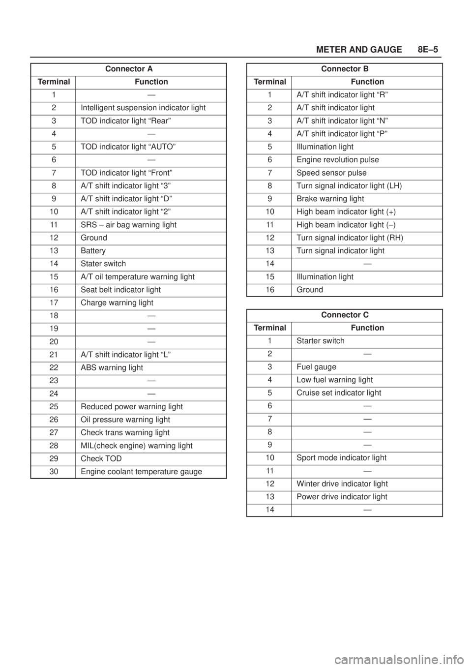
METER AND GAUGE8E±5
Connector A
TerminalFunction
1Ð
2Intelligent suspension indicator light
3TOD indicator light ªRearº
4Ð
5TOD indicator light ªAUTOº
6Ð
7TOD indicator light ªFrontº
8A/T shift indicator light ª3º
9A/T shift indicator light ªDº
10A/T shift indicator light ª2º
11SRS ± air bag warning light
12Ground
13Battery
14Stater switch
15A/T oil temperature warning light
16Seat belt indicator light
17Charge warning light
18Ð
19Ð
20Ð
21A/T shift indicator light ªLº
22ABS warning light
23Ð
24Ð
25Reduced power warning light
26Oil pressure warning light
27Check trans warning light
28MIL(check engine) warning light
29Check TOD
30Engine coolant temperature gauge
Connector B
TerminalFunction
1A/T shift indicator light ªRº
2A/T shift indicator light
3A/T shift indicator light ªNº
4A/T shift indicator light ªPº
5Illumination light
6Engine revolution pulse
7Speed sensor pulse
8Turn signal indicator light (LH)
9Brake warning light
10High beam indicator light (+)
11High beam indicator light (±)
12Turn signal indicator light (RH)
13Turn signal indicator light
14Ð
15Illumination light
16Ground
Connector C
TerminalFunction
1Starter switch
2Ð
3Fuel gauge
4Low fuel warning light
5Cruise set indicator light
6Ð
7Ð
8Ð
9Ð
10Sport mode indicator light
11Ð
12Winter drive indicator light
13Power drive indicator light
14Ð
Page 1908 of 2100
8F±32BODY STRUCTURE
General Description (Body)
This publication contains essential removal, installation,
adjustment and maintenance procedures.
Instrument Panel Assembly
Parts Location
740R200024
Legend
(1) Cross Beam
(2) Vent Duct Assembly
(3) Instrument Panel Stay
(4) Passenger Air Bag
(5) Passenger Air Bag Cover
(6) Dash Side Trim Panel (RH)
(7) Instrument Upper Reinforcement
(8) Glove Box Side Reinforcement
(9) Passenger Lower Bracket
(10) Glove Box
(11) Display Unit
(12) Audio Kit(13) Front Console Assembly
(14) Knee Pad
(15) Center Cluster Assembly
(16) Cluster Upper Cover
(17) Instrument Panel Driver Lower Cover
Assembly
(18) Driver Knee Bolster Assembly
(19) Dash Side Trim Panel (LH)
(20) Meter Cluster Assembly
(21) Instrument Panel Center Reinforcement
(22) Meter Assembly
(23) Instrument Panel Assembly
(24) Instrument Harness Assembly