Page 1578 of 2100
6G±11
ENGINE LUBRICATION (6VE1 3.5L)
Oil Pump Oil Seal
Removal
1. Disconnect battery ground cable.
2. Drain engine oil.
3. Remove crankshaft pulley.
�Refer to removal procedure for Crankshaft Pulley in
this manual.
4. Remove timing belt.
�Refer to removal procedure for Timing Belt in this
manual.
5. Remove timing pulley from crankshaft.
6. Remove oil pump oil seal using a sealer puller.
NOTE: Take care not to damage sealing surfaces of oil
pump and crankshaft when removing oil seal.
Installation
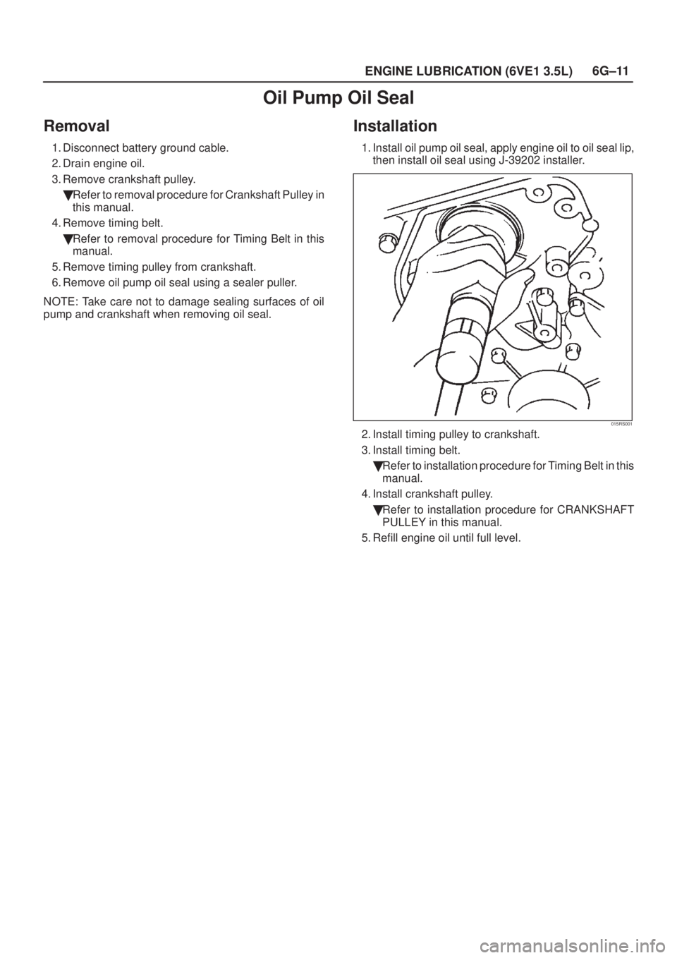
1. Install oil pump oil seal, apply engine oil to oil seal lip,
then install oil seal using J-39202 installer.
015RS001
2. Install timing pulley to crankshaft.
3. Install timing belt.
�Refer to installation procedure for Timing Belt in this
manual.
4. Install crankshaft pulley.
�Refer to installation procedure for CRANKSHAFT
PULLEY in this manual.
5. Refill engine oil until full level.
Page 1579 of 2100
6G±12
ENGINE LUBRICATION (6VE1 3.5L)
Oil Filter
Removal
1. Disconnect battery ground cable.
2. Drain engine oil.
3. Remove oil filter using J-36390 filter wrench.
Installation
1. Apply a light coat of engine oil to the oil filter gasket.
2. Hand tighten the filter until the gasket contacts the
sealing face.
3. Using J±36390 filter wrench, tighten the filter an
additional 7/8 turn or by torque 22 N´m (16 lb ft).
050RW001
Legend
(1) Oil Pump
(2) Oil Filter
(3) Oil Gallery
(4) From Filter
(5) To Filter
4. Fill the oil to the proper lever by following the oil level
check procedures.
5. Reconnect battery ground cable.
6. Run the engine and inspect for leaks.
Page 1582 of 2100
6H±2
ENGINE SPEED CONTROL SYSTEM (6VE1 3.5L)
Accelerator Pedal
Accelerator Pedal and Associated
Parts
101RY00006
Legend
(1) Accelerator Position Sensor
(2) Accelerator Pedal Assembly
Removal
1. Disconnect battery ground cable.
2. Disconnect Accelerator position (AP) sensor (1)
connector from Accelerator pedal assembly.
3. Remove Accelerator pedal assembly (2).
Installation
1. Install Accelerator pedal assembly (2).
2. Connect AP sensor (1) harness connector.
3. Connect battery ground cable.
Page 1611 of 2100

Changing Transmission Fluid
There is no need to change the transmission fluid unless
the transmission is used under one or more of the
following heavy duty cond")
7A±27 AUTOMATIC TRANSMISSION (4L30±E)
Changing Transmission Fluid
There is no need to change the transmission fluid unless
the transmission is used under one or more of the
following heavy duty conditions.
A. Repeated short trips
B. Driving on rough roads
C. Driving on dusty roads
D. Towing a trailer
If the vehicle is used under these conditions, change the
fluid every 20,000 miles (32,000 km).
1. Place a large drain pan under the oil pan.
2. Remove the transmission oil drain screw (2) and drain
fluid.
3. Tighten drain screw (2).
Torque: 38 Nwm (28 lb ft)
4. Remove the transmission overfill screw (1) and fill
transmission through overfill screw opening, using
DEXRON)±III ATF.
NOTE: Add transmission fluid until it flows out over the
overfill screw opening.
5. Let engine idle until a fluid temperature between 32�C
(90�F) and 57�C (135�F) is reached.
6. Add transmission fluid until it flows out over the overfill
screw opening, then close the overfill screw (1).
Torque: 38 Nwm (28 lb ft)NOTE: To prevent fluid leaks, the overfill screw and oil
drain screws gasket must be replaced each time these
screws are removed.
NOTE: Check transmission fluid temperature with scan
tool.
7. Reset ªOil Life Monitorº data by using Tech 2.
Refer to
Tech 2 OBD II Connection in Transmission
Control System (4L30-E) section.
242R200001
Selector Lever
Inspection
1. Make sure that when the selector lever is shifted from
ªPº to ªLº, a ªclickingº can be felt at each shift position.
Make sure that the gear corresponds to that of the
position plate indicator.
2. Check to see if the selector lever can be shifted as
shown in illustration.
C07RW009
Removal
1. Disconnect battery ground cable.
2. Set ignition Key in ªLOCKº position and selector lever
in ºPº position.
3. Remove knee pads (1), cluster upper cover (2) and
center cluster assembly (3).
740R200021
Page 1613 of 2100

10. Remove selector lever subassembly.
256R200005
Installation
1. Install selector lever subassembly.
2. Connect harness connector.
3. Connect shift lock cable.")
7A±29 AUTOMATIC TRANSMISSION (4L30±E)
10. Remove selector lever subassembly.
256R200005
Installation
1. Install selector lever subassembly.
2. Connect harness connector.
3. Connect shift lock cable.
�Refer to
Shift Lock Cable in this section.
4. Connect select cable.
�Refer to
Select Cable in this section.
5. Install selector lever knob and cover assembly.
6. Install front console.
7. Install rear console.
8. Install center cluster assembly, cluster upper cover
and knee pads.
9. Connect negative (±) battery cable.
10. After installation, make sure that the selector lever
operates normally, and that each selector position is
properly indicated. (The red mark shows through the
window.)
Select Cable
Removal
1. Set selector lever in ªPº position.
2. Remove knee pads, cluster upper cover, center
cluster assembly, rear console, front console,
selector lever knob and cover assembly.
�Refer to
Selector Lever in this section.
3. Disconnect inner cable by pulling projection on pin.
256R200006
Page 1619 of 2100

5. Check that cable moves smoothly, lightly pulling outer
cable rearward.
6. Connect lock adjust, aligning ªTº mark in the ªUpº
position.
256R200003
7. Abou")
7A±35 AUTOMATIC TRANSMISSION (4L30±E)
5. Check that cable moves smoothly, lightly pulling outer
cable rearward.
6. Connect lock adjust, aligning ªTº mark in the ªUpº
position.
256R200003
7. About following installation steps, refer to Selector
Lever in this section.
8. Check the shift lock operation:
a. Selector lever should not be moved out of ªPº
position with ignition key in ªLockº position.
b. Selector lever can be moved out of ªPº position with
ignition key in ªONºposition only when brake pedal
is depressed.
c. ignition key can be turned to ªLOCKº position only
when selector lever is in ªPº position (key can be
pulled out).
9. If a. and c. fail, readjust cable. If b. fails, readjust
connector wiring and brake pedal switch.
Mode Switch
Removal
1. Place selector lever in neutral.
2. Disconnect battery ground cable.
3. Remove mode switch cover (1) (V6).
4. Disconnect selector lever (2) from the mode switch.
5. Remove bracket with cable (3).
6. Disconnect transmission harness from the mode
switch connector (4).
7. Remove bracket with mode switch connector from
the transmission case.
8. Remove mode switch connector (4) from the bracket
(5).
9. Remove two mode switch bolts and nut then remove
mode switch (6).
210RW014
Page 1622 of 2100
7A±38
AUTOMATIC TRANSMISSION (4L30±E)
Removal
1. Disconnect battery ground cable.
2. Remove transfer protector (4y4) and fairing plate.
150R200001
3. Remove rear propeller shaft and front propeller shaft
(4y4).
NOTE: Apply alignment marks on the flange at both front
and rear sides.
401RW008
401R200008
4. Remove center exhaust pipe (4y4).
5. Remove fuel pipe heat protector and clip from third
crossmember.
6. Disconnect fuel pipe bracket from third crossmember.
141RW004
Page 1631 of 2100

Solenoid (Main Case Valve Body)
Removal
1. Raise the vehicle and support it on jack stands.
2. Disconnect battery ground cable.
3. Remove transfer protector (4")
7A±47 AUTOMATIC TRANSMISSION (4L30±E)
Solenoid (Main Case Valve Body)
Removal
1. Raise the vehicle and support it on jack stands.
2. Disconnect battery ground cable.
3. Remove transfer protector (4y4).
4. Drain fluid.
5. Support transfer case with a jack and remove third
crossmember.
6. Remove sixteen 10 mm screws, main case oil pan,
magnet, and gasket.
7. Remove three 13 mm screws, oil filter.
8. Disconnect wiring harness from band control
solenoid and shift solenoids. Pull only on connectors,
not on wiring harness.
9. Remove spring pin for shift solenoid A, shift solenoid
B, and band control solenoid respectively, using
suitable pliers taking care not to damage solenoids.
210RW010
244RW003
10. Remove shift solenoid A, shift solenoid B, band
control solenoid, and gaskets from main case valve
body. Do not pull on wiring harness. Remove
solenoids by grasping the metal tip.
Installation
1. Install shift solenoid A, shift solenoid B, band control
solenoid with new gaskets to main case valve body
respectively.
2. Carefully install spring pin with hammer to avoid
damage to valve body, etc.
243RW004
3. Connect wiring harness to solenoids.
4. Install oil filter with a new gasket and the three 13 mm
screws. Tighten the screws to the specified torque.
Torque: 20 Nwm (15 lb ft)
5. Install magnet, main case oil pan with new gasket,
sixteen 10 mm screws. Tighten the screws to the
specified torque.
Torque: 11 Nwm (96 lb in)
6. Install third crossmember and rear mount nuts.
Tighten the nuts and bolts to the specified torque.
Third crossmember bolt: 116 Nwm (85 lb ft)
Rear mount nut: 50 Nwm (37 lb ft)
7. Install the transfer protector. Tighten the bolts to the
specified torque (4y4).
Torque: 37 Nwm (27 lb ft)
8. Fill transmission through the overfill screw hole of oil
pan, using ATF DEXRON)±III. Refer to
Changing
Transmission Fluid in this section.
9. Connect the battery ground cable.

Oil Filter
Removal
1. Disconnect battery ground cable.
2. Drain engine oil.
3. Remove oil filter using J-36390 filter wrench.
Installation
1. Apply a light coat o")

Accelerator Pedal
Accelerator Pedal and Associated
Parts
101RY00006
Legend
(1) Accelerator Position Sensor
(2) Accelerator Pedal Assembly
Removal
1. Disco")

Removal
1. Disconnect battery ground cable.
2. Remove transfer protector (4y4) and fairing plate.
150R200001
3. Remove rear propeller shaft and front propeller")