Page 391 of 4323

A21025
Ignition Coil Connector
I1
I2
I3I4
I5I6
I7I8
Wire Harness Side:
B17412
E8
IGT8 IGT2
IGT4
IGT5IGT6IGT3 IGT7IGT1
ECM Connector
± DIAGNOSTICSENGINE
DI±197
391 Author�: Date�:
2005 SEQUOIA (RM1146U)
Check the harness and connector between the ignition coil
and the ECM (IGT terminal) connectors:
PREPARATION:
(a) Disconnect the I1, I2, I3, I4, I5, I6, I7 or I8 ignition coil con-
nector.
(b) Disconnect the E8 ECM connector.
CHECK:
Check the resistance between the wire harness side connec-
tors.
OK:
Standard:
Tester ConnectionSpecified Condition
Ignition coil (I1±3) ± IGT1 (E8±8)Below 1 W
Ignition coil (I2±3) ± IGT2 (E8±15)Below 1 W
Ignition coil (I3±3) ± IGT3 (E8±11)Below 1 W
Ignition coil (I4±3) ± IGT4 (E8±10)Below 1 W
Ignition coil (I5±3) ± IGT5 (E8±13)Below 1 W
Ignition coil (I6±3) ± IGT6 (E8±12)Below 1 W
Ignition coil (I7±3) ± IGT7 (E8±14)Below 1 W
Ignition coil (I8±3) ± IGT8 (E8±9)Below 1 W
Ignition coil (I1±3) or IGT1 (E8±8) ±
Body ground10 kW or higher
Ignition coil (I2±3) or IGT2 (E8±15) ±
Body ground10 kW or higher
Ignition coil (I3±3) or IGT3 (E8±11) ±
Body ground10 kW or higher
Ignition coil (I4±3) or IGT4 (E8±10) ±
Body ground10 kW or higher
Ignition coil (I5±3) or IGT5 (E8±13) ±
Body ground10 kW or higher
Ignition coil (I6±3) or IGT6 (E8±12) ±
Body ground10 kW or higher
Ignition coil (I7±3) or IGT7 (E8±14) ±
Body ground10 kW or higher
Ignition coil (I8±3) or IGT8 (E8±9) ±
Body ground10 kW or higher
OK Replace ignition coil with igniter, then confirm
that there is no misfire.
NG
Repair or replace harness or connector.
Page 392 of 4323
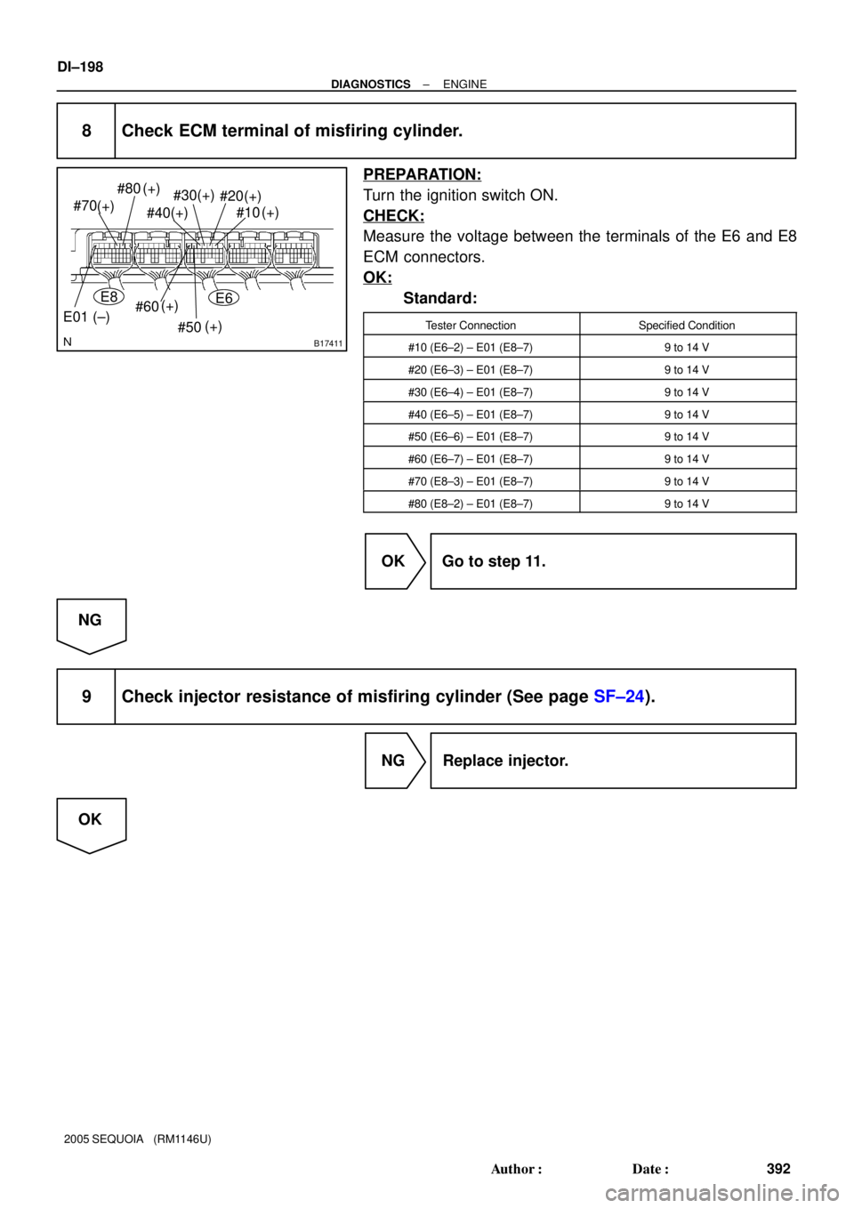
B17411
#80
#70
#60
#50 #30
#20
#10
(+) (+)
(+)
(+)
(+) (+)(+)
#40(+)
E01 (±)
E8E6
DI±198
± DIAGNOSTICSENGINE
392 Author�: Date�:
2005 SEQUOIA (RM1146U)
8 Check ECM terminal of misfiring cylinder.
PREPARATION:
Turn the ignition switch ON.
CHECK:
Measure the voltage between the terminals of the E6 and E8
ECM connectors.
OK:
Standard:
Tester ConnectionSpecified Condition
#10 (E6±2) ± E01 (E8±7)9 to 14 V
#20 (E6±3) ± E01 (E8±7)9 to 14 V
#30 (E6±4) ± E01 (E8±7)9 to 14 V
#40 (E6±5) ± E01 (E8±7)9 to 14 V
#50 (E6±6) ± E01 (E8±7)9 to 14 V
#60 (E6±7) ± E01 (E8±7)9 to 14 V
#70 (E8±3) ± E01 (E8±7)9 to 14 V
#80 (E8±2) ± E01 (E8±7)9 to 14 V
OK Go to step 11.
NG
9 Check injector resistance of misfiring cylinder (See page SF±24).
NG Replace injector.
OK
Page 397 of 4323
 (104) (140) (176)(32) (68) (212)
A21042
Ohmmeter
Acceptable
TEMPERATURE �C (�F)
RESISTANCE KW
± DIAGNOSTICSENGINE
DI±203
397 Au")
S01196S01699
30
20
10
5
3
02040 0.11
0.3
0.2 0.52
60 80 100 ±20
(±4) (104) (140) (176)(32) (68) (212)
A21042
Ohmmeter
Acceptable
TEMPERATURE �C (�F)
RESISTANCE KW
± DIAGNOSTICSENGINE
DI±203
397 Author�: Date�:
2005 SEQUOIA (RM1146U)
18 Check engine coolant temperature sensor.
PREPARATION:
Remove the engine coolant temperature sensor.
CHECK:
Measure the resistance between the terminals of the engine
coolant temperature sensor.
Resistance:
Tester ConnectionSpecified Condition
1 ± 22.32 to 2.59 kW (20�C (68�F))
1 ± 20.310 to 0.326 kW (80�C (176�F))
NOTICE:
In case of checking the engine coolant temperature sensor
in the water, be careful not to allow water to go into the ter-
minals. After checking, dry the sensor.
HINT:
Alternate procedure: Connect an ohmmeter to the installed en-
gine coolant temperature sensor and read the resistance. Use
an infrared thermometer to measure the engine temperature in
the immediate vicinity of the sensor. Compare these values to
the resistance/temperature graph. Change the engine temper-
ature (by warming up or cooling down) and repeat the test.
NG Replace
engine coolant temperature sensor.
OK
19 Switch step by number of misfire cylinder (Refer to the result of step 4).
High misfire rate cylinderProceed to
1 or 2 cylindersA
More than 3 cylindersB
B Go to step 5.
A
Check for intermittent problems
(See page DI±11).
Page 399 of 4323

Reference: Inspection using the oscilloscope.
The correct waveform")
A23648
GND 1V/ DIV KNK1 Signal Waveform
1 msec./ Division
± DIAGNOSTICSENGINE
DI±205
399 Author�: Date�:
2005 SEQUOIA (RM1146U)
Reference: Inspection using the oscilloscope.
The correct waveform is as shown.
ItemDetails
Terminal
KNK1 ± EKNK
or
KNK2 ± EKN2
Equipment Settings0.01 to 10 V/Division,
0.01 to 10 msec./Division
ConditionAfter warming up the engine,
keep the engine speed at 4,000 rpm.
MONITOR DESCRIPTION
The knock sensor located on the cylinder block detects spark knock.
When spark knock occurs, the sensor pick±up vibrates in a specific frequency range. When the ECM detects
the voltage in this frequency range, it retards the ignition timing to suppress the spark knock.
If there is a defect in the knock sensor or an open or short circuit, the voltage level will deviate outside the
normal operating range. The ECM interprets this deviation as a defect in the knock sensor and sets a DTC.
Example:
When the knock sensor voltage output is less than 0.5 V, or more than 4.5 V, and if either the condition contin-
ues for more than 3 sec.
MONITOR STRATEGY
P0325Knock sensor (Bank 1) range check (Chattering)
P0327Knock sensor (Bank 1) range check (Low volt-
age)
RltdDTC
P0328Knock sensor (Bank 1) range check (High volt-
age)
Related DTCsP0330Knock sensor (Bank 2) range check (Chattering)
P0327Knock sensor (Bank 2) range check (Low volt-
age)
P0328Knock sensor (Bank 2) range check (High volt-
age)
Main sensors/componentsKnock sensor
Required sensors/componentsRelated sensors/components
Crankshaft position sensor, Camshaft position
sensor, Engine coolant temperature sensor,
Mass air flow meter
Frequency of operationContinuous
Duration1 sec.
MIL operationImmediate
Sequence of operationNone
TYPICAL ENABLING CONDITIONS
ItSpecificationItemMinimumMaximum
The monitor will run whenever these
DTCs are not presentSee page DI±18
Battery voltage10.5 V±
Time after engine start5 sec.±
Page 401 of 4323

A23476
ECM EB4
EB4
Female
Connector Male
Connector Knock Sensor
83 4
783 4
7 2 1
2 1
E7
E7
E7
E728
21
20KNK1
EKNK
KNK2
EKN2 29
± DIAGNOSTICSENGINE
DI±207
401 Author�: Date�:
2005 SEQUOIA (RM1146U)
1 Connect hand±held tester, and check knock sensor circuit.
PREPARATION:
(a) Disconnect the EB4 connector.
(b) Using lead wires, connect the EB4 connectors as follows.
Male Connector ± Female Connector
Terminal 4 ± Terminal 8
Terminal 3 ± Terminal 7
Terminal 8 ± Terminal 4
Terminal 7 ± Terminal 3
(c) Warm up the engine.
(d) Run the engine at 3,000 rpm for 10 seconds or more.
CHECK:
(a) Connect the hand±held tester to the DLC3.
(b) Turn the ignition switch to ON and turn the hand±held tes-
ter ON.
(c) Select the item: DIAGNOSIS / ENHANCED OBD II / DTC
INFO / CURRENT CODES.
(d) Read DTCs.
Result :
DisplayProceed to
DTCs same as when vehicle brought in
P0325, P0327, P0328 " P0325, P0327, P0328
or
P0330, P0332, P0333 " P0330, P0332, P0333
A
DTC different from when vehicle brought in
P0325 " P0330
or
P0330 " P0325
B
DTCs different from when vehicle brought in
P0327, P0328 " P0332, P0333
or
P0332, P0333 " P0327, P0328
C
(e) Reconnect the EB4 connector.
B Go to step 4.
C Go to step 5.
A
Page 402 of 4323
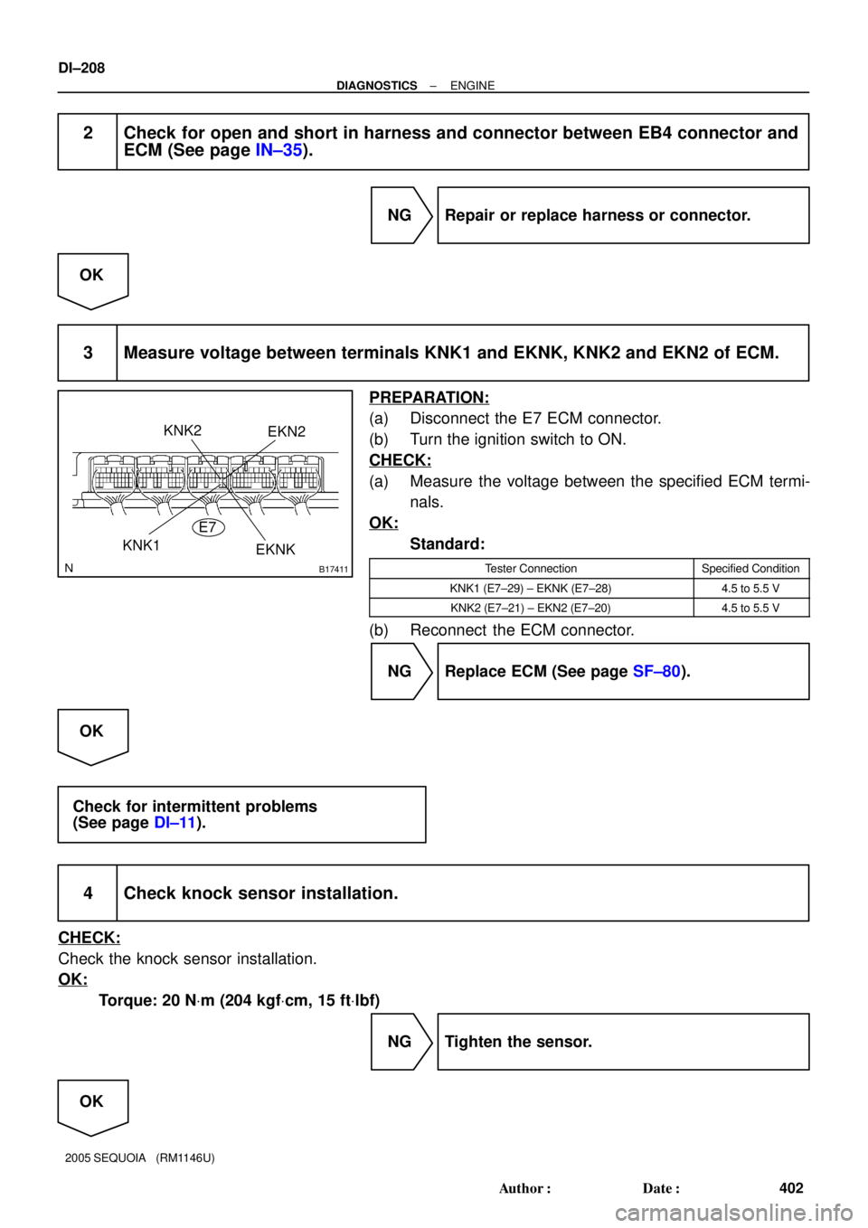
B17411
KNK1
KNK2EKN2
EKNK E7
DI±208
± DIAGNOSTICSENGINE
402 Author�: Date�:
2005 SEQUOIA (RM1146U)
2 Check for open and short in harness and connector between EB4 connector and
ECM (See page IN±35).
NG Repair or replace harness or connector.
OK
3 Measure voltage between terminals KNK1 and EKNK, KNK2 and EKN2 of ECM.
PREPARATION:
(a) Disconnect the E7 ECM connector.
(b) Turn the ignition switch to ON.
CHECK:
(a) Measure the voltage between the specified ECM termi-
nals.
OK:
Standard:
Tester ConnectionSpecified Condition
KNK1 (E7±29) ± EKNK (E7±28)4.5 to 5.5 V
KNK2 (E7±21) ± EKN2 (E7±20)4.5 to 5.5 V
(b) Reconnect the ECM connector.
NG Replace ECM (See page SF±80).
OK
Check for intermittent problems
(See page DI±11).
4 Check knock sensor installation.
CHECK:
Check the knock sensor installation.
OK:
Torque: 20 NVm (204 kgfVcm, 15 ftVlbf)
NG Tighten the sensor.
OK
Page 403 of 4323
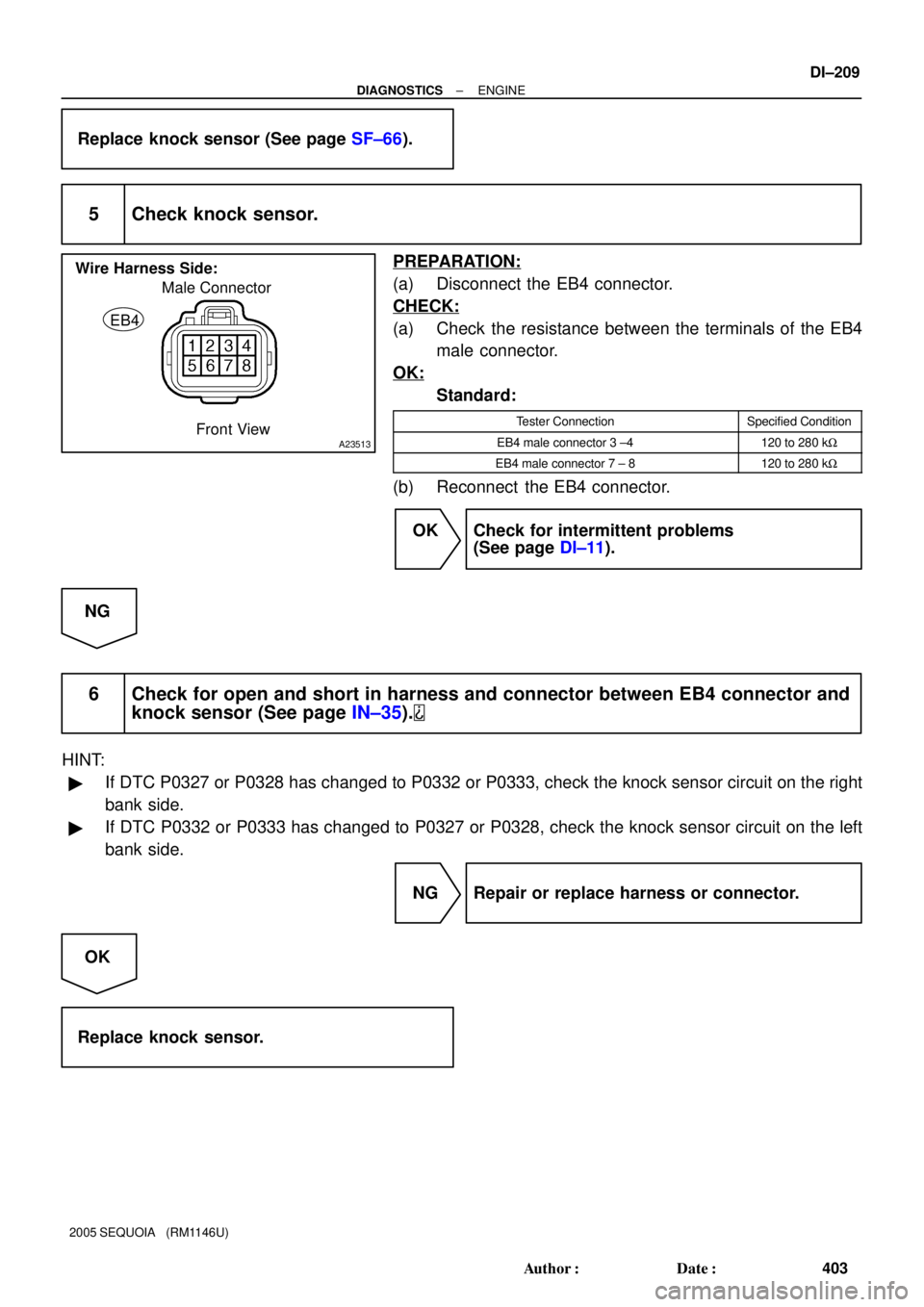
A23513
Male Connector
EB4
Wire Harness Side:
Front View
± DIAGNOSTICSENGINE
DI±209
403 Author�: Date�:
2005 SEQUOIA (RM1146U)
Replace knock sensor (See page SF±66).
5 Check knock sensor.
PREPARATION:
(a) Disconnect the EB4 connector.
CHECK:
(a) Check the resistance between the terminals of the EB4
male connector.
OK:
Standard:
Tester ConnectionSpecified Condition
EB4 male connector 3 ±4120 to 280 kW
EB4 male connector 7 ± 8120 to 280 kW
(b) Reconnect the EB4 connector.
OK Check for intermittent problems
(See page DI±11).
NG
6 Check for open and short in harness and connector between EB4 connector and
knock sensor (See page IN±35).
HINT:
�If DTC P0327 or P0328 has changed to P0332 or P0333, check the knock sensor circuit on the right
bank side.
�If DTC P0332 or P0333 has changed to P0327 or P0328, check the knock sensor circuit on the left
bank side.
NG Repair or replace harness or connector.
OK
Replace knock sensor.
Page 407 of 4323

INSPECTION PROCEDURE
HINT:
�Read freeze frame data using the hand±held te")
A21026
Component Side
C2
Crankshaft Position Sensor
± DIAGNOSTICSENGINE
DI±213
407 Author�: Date�:
2005 SEQUOIA (RM1146U)
INSPECTION PROCEDURE
HINT:
�Read freeze frame data using the hand±held tester. Freeze frame records the engine conditions when
a malfunction is detected. When troubleshooting it is useful for determining whether the vehicle was
running or stopped. the engine was warmed up or not, the air±fuel ratio lean or rich, etc. at the time
of the malfunction.
�READ VALUE ON HAND±HELD TESTER
(a) Connect the hand±held tester to the DLC3.
(b) Start the engine and push the hand±held tester tool main switch ON.
(c) When using hand±held tester, enter the following menu: ºDIAGNOSIS / ENHANCED OBD II / DATA
LIST / ALL / ENGINE SPDº.
�The engine speed can be confirmed in DATA LIST using the hand±held tester. If there are no NE sig-
nals from the crankshaft position sensor despite the engine revolving, the engine speed will be indi-
cated as zero. If voltage output of the crankshaft position sensor is insufficient, the engine speed will
be indicated as lower RPM (than the actual RPM).
1 Check resistance of crankshaft position sensor.
PREPARATION:
Disconnect the C2 crankshaft position sensor connector.
CHECK:
Measure the resistance between terminals 1 and 2.
OK:
Standard:
Tester ConnectionSpecified Condition
1 ± 2985 to 1,600 W at cold
1 ± 21,265 to 1,890 W at hot
NOTICE:
º Coldº and ºHotº shown above mean the temperature of
the coils themselves. ºColdº is form ±10°C (14°F) to 50°C
(122°F) and ºHotº is from 50°C (122°F) to 100°C (212°F).
NG Replace crankshaft position sensor.
OK