Page 235 of 4323

�Freeze frame data:
The freeze frame data records the engine conditions (fuel
syste")
A04550
12 345678
11 12 13 14 15 16 910
DLC3
± DIAGNOSTICSENGINE
DI±41
235 Author�: Date�:
2005 SEQUOIA (RM1146U)
�Freeze frame data:
The freeze frame data records the engine conditions (fuel
system, calculated load, engine coolant temperature, fuel
trim, engine speed, vehicle speed, etc.) when a malfunc-
tion is detected. When troubleshooting, freeze frame data
can help determine if the vehicle was running or stopped,
if the engine was warmed up or not, if the air±fuel ratio
was lean or rich, as well as other data from the time when
a malfunction occurred.
Priorities for troubleshooting:
When multiple DTCs occur, find out the order in which the DTCs
should be inspected by checking the component's DTC chart.
If no instructions are written in the DTC chart, check DTCs in the
following order of priority:
(a) DTCs other than fuel trim malfunction DTCs (P0171,
P0172, P0174 and P0175) and misfire DTCs (P0300 to
P0308).
(b) Fuel trim malfunction DTCs (P0171, P0172, P0174 and
P0175).
(c) Misfire DTCs (P0300 to P0308).
4. CHECK DLC3
The vehicle's ECM uses the ISO 9141±2 for communica-
tion protocol. The terminal arrangement of the DLC3 com-
plies with SAE J1962 and matches the ISO 9141±2 for-
mat.
SymbolTerminal DescriptionConditionSpecified Condition
SIL (7) ± SG (5)Bus º+º lineDuring transmissionPulse generation
CG (4) ± Body groundChassis groundAlwaysBelow 1 W
SG (5) ± Body groundSignal groundAlwaysBelow 1 W
BAT (16) ± Body groundBattery positiveAlways11 to 14 V
CANH (6) ± CANL (14)HIGH±level CAN bus lineIgnition switch OFF54 to 69 W
CANH (6) ± Battery positiveHIGH±level CAN bus lineIgnition switch OFF1 MW or higher
CANH (6) ± CG (4)HIGH±level CAN bus lineIgnition switch OFF1 kW or higher
CANL (14) ± Battery positiveLOW±level CAN bus lineIgnition switch OFF1 MW or higher
CANL (6) ± CG (4)LOW±level CAN bus lineIgnition switch OFF1 kW or higher
HINT:
Connect the cable of the hand±held tester to the DLC3, turn the
ignition switch ON and attempt to use the hand±held tester. If
the screen displays UNABLE TO CONNECT TO VEHICLE, a
problem exists in the vehicle side or the tester side.
�If the communication is normal when the tool is connected
to another vehicle, inspect the DLC3 on the original ve-
hicle.
Page 239 of 4323
± DIAGNOSTICSENGINE
DI±45
239 Author�: Date�:
2005 SEQUOIA (RM1146U)
3. CLEAR DTC (Not using the hand±held tester)
(a) Remove the EFI No. 1 and ETCS fuses from the engine
room J/B for more than 60 seconds, or disconnect the bat-
tery terminal for more than 60 seconds.
After disconnecting the battery terminal, perform the ºINI-
TIALIZEº procedure.
Page 247 of 4323
A/C SIG
A/C signal: ON or OFFON: A/C ON
ELECT LOAD SIGElectrical load signal:
ON or OFFON: Headlights or defogger is
turned ON")
± DIAGNOSTICSENGINE
DI±53
247 Author�: Date�:
2005 SEQUOIA (RM1146U)A/C SIG
A/C signal: ON or OFFON: A/C ON'
ELECT LOAD SIGElectrical load signal:
ON or OFFON: Headlights or defogger is
turned ON'
STOP LIGHT SWStop lamp switch:
ON or OFFON: brake pedal is depressed.'
+BM
Whether or not electric throttle
control system power inputted:
ON or OFF
ON: Idling'
+BM VOLTAGE+BM voltage:
Min.: 0, Max.: 19.9210 to 15 V: IdlingETCS service data
BATTERY VOLTAGEBattery voltage:
Min.: 0 V, Max.: 65.535 V9 to 14 V: Idling'
ACTUATOR POWERActuator power supply:
ON or OFFON: IdlingETCS service data
ATM PRESSUREAtmospheric pressure:
Min.: 0 kPa, Max.: 150 kPaEquivalent to atmospheric pres-
sure (absolute pressure)'
SECOND AIR VSVSecondary air injection system
statusON: Secondary air injection sys-
tem operation'
ACT VSVA/C cut status for Active Test:
ON or OFF'Active Test support data
EVAP (Purge) VSVVSV status for EVAP control:
ON or OFF'Active Test support data
FUEL PUMP / SPDFuel pump/speed status:
ON or OFF'Active Test support data
VVT CTRL B1VVT control status:
ON or OFF'Active Test support data
VVT CTRL B2VVT control status:
ON or OFF'Active Test support data
VACUUM PUMP
Key±off EVAP system pump sta-
tus:
ON or OFF
'Active Test support data
EVAP VENT VAL
Key±off EVAP system vent valve
status:
ON or OFF
'Active Test support data
TC/TE1TC and TE1 terminal of DLC3:
ON or OFF''
VVTL AIM ANGL #1VVT aim angle (bank 1):
Min.: 0 %, Max.: 100 %0 %: IdlingVVT duty signal value during intru-
sive operation
VVTL AIM ANGL #2VVT aim angle (bank 1):
Min.: 0 %, Max.: 100 %0 %: IdlingVVT duty signal value during intru-
sive operation
VVT CHNG ANGL #1VVT change angle:
Min.: 0�FR, Max.: 60�FR0 to 5 �FR: IdlingDisplacement angle during intru-
sive operation
VVT CHNG ANGL #2VVT change angle:
Min.: 0�FR, Max.: 60�FR0 to 5 �FR: IdlingDisplacement angle during intru-
sive operation
VVT OCV DUTY B1VVT OCV operation duty:
Min.: 0 %, Max.: 100 %0 %: IdlingRequested duty value for intrusive
operation
VVT OCV DUTY B2VVT OCV operation duty:
Min.: 0 %, Max.: 100 %0 %: IdlingRequested duty value for intrusive
operation
FC IDLFuel cut idle:
ON or OFFON: Fuel cut operation
FC IDL = ºONº when throttle valve
fully closed and engine speed over
2,800 rpm
Page 270 of 4323
A31449A23511
Valve Battery ±
Battery +
DI±76
± DIAGNOSTICSENGINE
270 Author�: Date�:
2005 SEQUOIA (RM1146U)
1 Check OCV circuit.
PREPARATION:
(a) Connect the hand±held tester to the DLC3.
(b) Start the engine and warm it up.
(c) Turn the ignition switch to ON and turn the hand±held tester ON.
CHECK:
(a) Select the item: DIAGNOSIS / ENHANCED OBD II / ACTIVE TEST / VVT CTRL B1 or VVT CTRL B2.
(b) Using the hand±held tester, operate the OCV and check the engine speed.
OK:
Standard:
Tester OperationSpecified Condition
OCV is OFFNormal engine speed
OCV is ONRough idle or engine stall
OK Check for intermittent problems
(See page DI±11).
NG
2 Check operation of OCV.
PREPARATION:
(a) Start the engine and warmed it up.
(b) Disconnect the OCV connector.
(c) Apply battery positive voltage between the terminals of
the OCV.
CHECK:
Check the engine speed.
OK:
Rough idle or engine stalled.
NG Replace OCV.
OK
Page 271 of 4323
A02397
OCV Signal Waveform
1 msec./Division5 V/
Division
GND
(A) (A) (A)
B17414ECM ConnectorE6
OC1+
OC1±
OC2+OC2±
E1
± DIAGNOSTICSENGINE
DI±77
271 Author�: Date�:
2005 SEQUOIA (RM1146U)
3 Check voltage between terminals OC1+ and OC1±, OC2+ and OC2± of ECM con-
nector.
CHECK:
(a) Inspection using the oscilloscope.
(b) During idling, check the waveform between the specified
terminals of the E6 ECM connector.
HINT:
The waveform frequency (A) is lengthened as the engine speed
becomes higher.
OK:
Standard:
The correct waveform is as shown.
NG Replace ECM (See page SF±80).
OK
Page 272 of 4323

4 Check for open and short in harn")
A23673
Wire Harness Side
C13
OCV Connector C14
B17414ECM ConnectorE6
OC1+
OC1±
OC2+OC2±
E1
DI±78
± DIAGNOSTICSENGINE
272 Author�: Date�:
2005 SEQUOIA (RM1146U)
4 Check for open and short in harness and connector between OCV and ECM.
PREPARATION:
(a) Disconnect the C13 or C14 OCV connector.
(b) Disconnect the E6 ECM connector.
CHECK:
(a) Check for resistance between the wire harness side con-
nectors.
OK:
Standard (Check for open):
Symbols (Terminal No.)Specified condition
OCV (C14±1) ± OC1+ (E6±17)Below 1 W
OCV (C14±2) ± OC1± (E6±16)Below 1 W
OCV (C13±1) ± OC2+ (E6±15)Below 1 W
OCV (C13±2) ± OC2± (E6±14)Below 1 W
Standard (Check for short):
Symbols (Terminal No.)Specified condition
OCV (C14±1) or OC1+ (E6±17) ± E1 (E6±1)10 kW or higher
OCV (C14±1) or OC1± (E6±16) ± E1 (E6±1)10 kW or higher
OCV (C13±1) or OC2+ (E6±15) ± E1 (E6±1)10 kW or higher
OCV (C13±1) or OC2± (E6±14) ± E1 (E6±1)10 kW or higher
NG Repair or replace harness or connector.
OK
Check for intermittent problems
(See page DI±11).
Page 276 of 4323
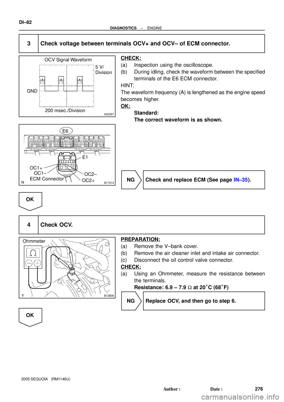
A02397
OCV Signal Waveform
200 msec./Division5 V/
Division
GND
(A) (A) (A)
B17414ECM ConnectorE6
OC1+
OC1±
OC2+OC2±
E1
B12806
Ohmmeter
DI±82
± DIAGNOSTICSENGINE
276 Author�: Date�:
2005 SEQUOIA (RM1146U)
3 Check voltage between terminals OCV+ and OCV± of ECM connector.
CHECK:
(a) Inspection using the oscilloscope.
(b) During idling, check the waveform between the specified
terminals of the E6 ECM connector.
HINT:
The waveform frequency (A) is lengthened as the engine speed
becomes higher.
OK:
Standard:
The correct waveform is as shown.
NG Check and replace ECM (See page IN±35).
OK
4 Check OCV.
PREPARATION:
(a) Remove the V±bank cover.
(b) Remove the air cleaner inlet and intake air connector.
(c) Disconnect the oil control valve connector.
CHECK:
(a) Using an Ohmmeter, measure the resistance between
the terminals.
Resistance: 6.9 ± 7.9 W at 20°C (68°F)
NG Replace OCV, and then go to step 6.
OK
Page 284 of 4323
 P0032, P0052 (High current):
Time after engine start10 sec.")
B17396
HT +B
AF± AF+ Sensor 1A/F Sensor Component Side:
Front View
DI±90
± DIAGNOSTICSENGINE
284 Author�: Date�:
2005 SEQUOIA (RM1146U) P0032, P0052 (High current):
Time after engine start10 sec.±
TYPICAL MALFUNCTION THRESHOLDS
Detection CriteriaThreshold
P0031, P0051 (Low current):
A/F sensor heater currentLess than 0.8 A
P0032, P0052 (High current):
A/F sensor heater currentMore than 10 A
COMPONENT OPERATING RANGE
ParameterStandard Value
A/F sensor heater current1.8 to 3.4 A at 20°C (68°F)
WIRING DIAGRAM
Refer to DTC P2195 on page DI±383.
INSPECTION PROCEDURE
HINT:
Read freeze frame data using a hand±held tester or OBD II scan tool. Freeze frame data record the engine
condition when malfunctions are detected. When troubleshooting, freeze frame data can help determine if
the vehicle was moving or stationary, if the engine was warmed up or not, if the air±fuel ratio was lean or
rich, and other data, from the time the malfunction occurred.
1 Check resistance of air±fuel ratio (A/F) sensor heater.
PREPARATION:
Disconnect the air±fuel ratio (A/F) sensor connector.
CHECK:
Measure resistance between the terminals of the A/F sensor
connector.
OK:
Standard:
Tester ConnectionSpecified Condition
HT (1) ± +B (2)1.8 W to 3.4 W at 20�C (68�F)
HT (1) ± AF± (4)10 kW or higher
NG Replace air±fuel ratio (A/F) sensor.
OK