Page 2277 of 4323
I28767
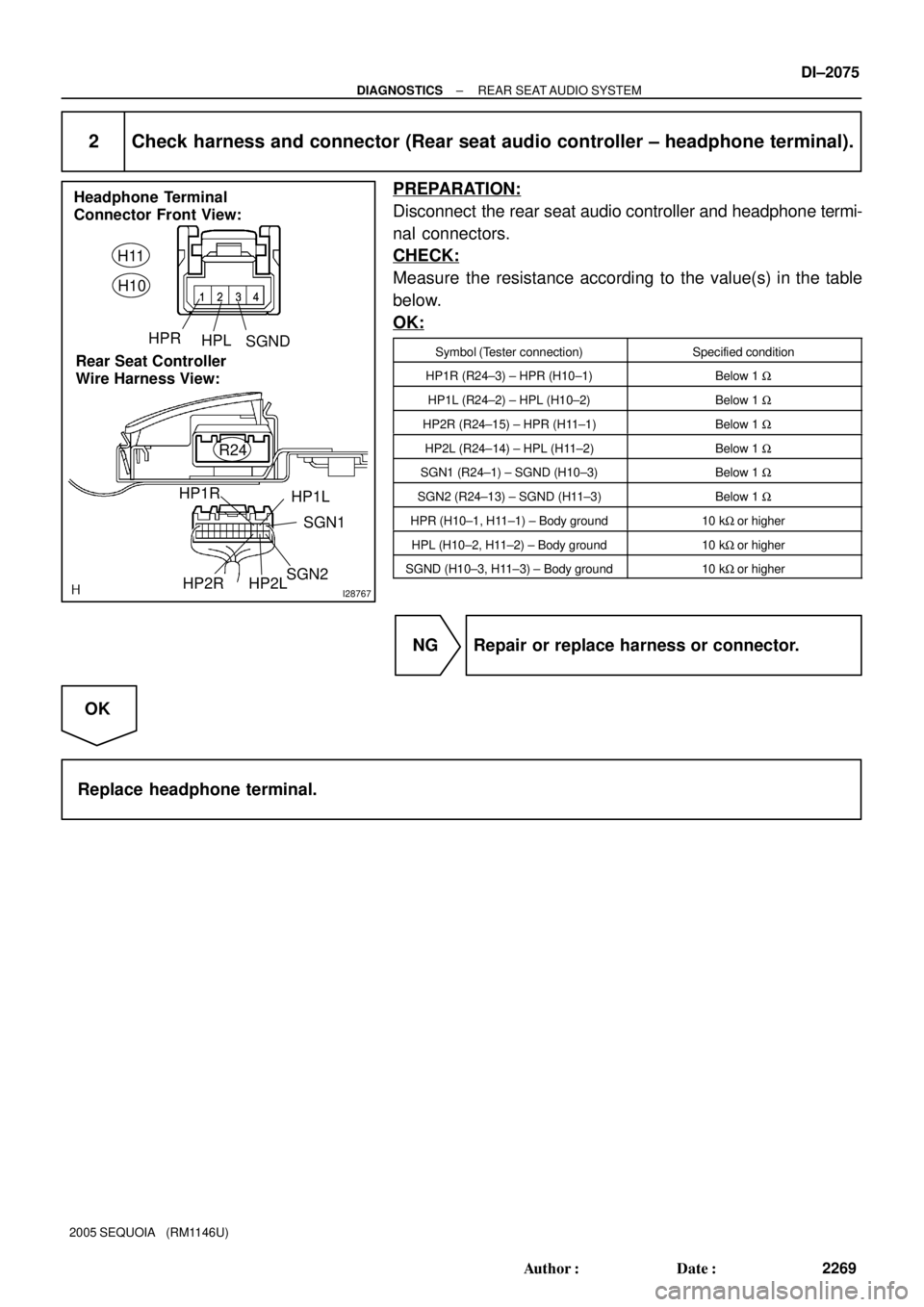
Headphone Terminal
Connector Front View:
Rear Seat Controller
Wire Harness View:H11
H10
HPRHPLSGND
SGN1
HP1L HP1R
SGN2HP2RR24HP2L
± DIAGNOSTICSREAR SEAT AUDIO SYSTEM
DI±2075
2269 Author�: Date�:
2005 SEQUOIA (RM1146U)
2 Check harness and connector (Rear seat audio controller ± headphone terminal).
PREPARATION:
Disconnect the rear seat audio controller and headphone termi-
nal connectors.
CHECK:
Measure the resistance according to the value(s) in the table
below.
OK:
Symbol (Tester connection)Specified condition
HP1R (R24±3) ± HPR (H10±1)Below 1 W
HP1L (R24±2) ± HPL (H10±2)Below 1 W
HP2R (R24±15) ± HPR (H11±1)Below 1 W
HP2L (R24±14) ± HPL (H11±2)Below 1 W
SGN1 (R24±1) ± SGND (H10±3)Below 1 W
SGN2 (R24±13) ± SGND (H11±3)Below 1 W
HPR (H10±1, H11±1) ± Body ground10 kW or higher
HPL (H10±2, H11±2) ± Body ground10 kW or higher
SGND (H10±3, H11±3) ± Body ground10 kW or higher
NG Repair or replace harness or connector.
OK
Replace headphone terminal.
Page 2280 of 4323
DIDAS±01
DI±2078
± DIAGNOSTICSREAR SEAT ENTERTAINMANT SYSTEM
2272 Author�: Date�:
2005 SEQUOIA (RM1146U)
REAR SEAT ENTERTAINMANT SYSTEM
PRECAUTION
NOTICE:
When disconnecting the battery terminal, initialize the following system after the terminal is recon-
nected.
System NameSee Page
Back Door Power Window Control SystemBE±77
Page 2281 of 4323
DIDAT±01
I27728
Radio and Navigation Assy (*1)
Radio Receiver Assy (*2)
Rear Door
SpeakerSteering Pad Switch
Instrument Panel J/B
� RAD NO. 2 Fuse
� ECU±B Fuse
� AM1 FuseEngine Room J/B
� RAD NO. 1 Fuse
� RAD NO. 3 Fuse
Ignition Switch
Headphone
Terminal
Front Door
Speaker and
Woofer
Stereo Component Amplifier
Multi±display
Controller
Sub±assy
*1: w/ Navigation System
*2: w/o Navigation SystemVTR TerminalDisc Player
Controller
Rear Door
Speaker
Front Door
Speaker and
Woofer
Tweeter
Television Display Assy
± DIAGNOSTICSREAR SEAT ENTERTAINMANT SYSTEM
DI±2079
2273 Author�: Date�:
2005 SEQUOIA (RM1146U)
LOCATION
Page 2282 of 4323
DIDAU±01
I28762
Radio and Navigation Assy
(*1)
or
Radio Receiver Assy (*2)
VTR
TerminalSpeakers Stereo Component
Amplifier Assy
Multi±display Controller
Wireless
HeadphoneDisplay Signal
Sound Signal
AVC±LAN
Headphone
Terminal
Switch AssyDisc
Player
ControllerTelevision
Display
Assy
*1: w/ Navigation System
*2: w/o Navigation System DI±2080
± DIAGNOSTICSREAR SEAT ENTERTAINMANT SYSTEM
2274 Author�: Date�:
2005 SEQUOIA (RM1146U)
SYSTEM DIAGRAM
Page 2283 of 4323

SYSTEM DESCRIPTION
1. Outline
�As a unique feature of Rear Seat Entertainment (RSE) system")
DIDAV±01
± DIAGNOSTICSREAR SEAT ENTERTAINMANT SYSTEM
DI±2081
2275 Author�: Date�:
2005 SEQUOIA (RM1146U)
SYSTEM DESCRIPTION
1. Outline
�As a unique feature of Rear Seat Entertainment (RSE) system, the front and rear seat occupants can
enjoy different audio±visual modes at the same time. Thus, this system offers enhanced entertainment
to the rear seat occupants.
�The rear seat occupants can control the audio±visual modes with the remote controller (switch assy),
and listen to audio by using wired or wireless headphones.
�The RSE system is controlled by the multi±display controller, and the communication among the audio
head unit, rear display assembly, and DVD player is established via an AVC±LAN (Audio Visual Com-
munication±Local Area Network).
2. Function of Main Component
Television Display Assy
�Displays DVD and video images in accordance with video signals from the RSE ECU.
�Receives signals from the remote controller and outputs them to the RSE ECU.
�Outputs audio signals to the wireless headphones in the form of infrared signals.
�Displays the audio±visual control screen.
�Displays the adjustment screen.
�Displays the diagnosis screen.
�The diagnosis screen appears when the diagnosis mode is started on the audio head unit.
Audio Head Unit
w/ Navigation system:
Radio and navigation assy
w/o Navigation system:
Radio receiver assy
�Outputs audio signals to the RSE ECU and the stereo component amplifier.
�Outputs a request to the RSE ECU to start the diagnosis mode.
RSE ECU (Multi±display Controller)
�Processes video and audio signals from the DVD player and video player and audio signals from the
audio head unit, and outputs them to the television display assembly and headphone terminals.
�Controls the distribution of the audio±visual mode to the front (audio head unit) and the rear (RSE).
Remote Controller (Switch Assy)Outputs various control signals of the RSE system to the television display assembly in the form of in-
frared signals.
Wireless Headphone
�Receives the audio signals from the television display assembly in the form of infrared signals.
�Volume adjustment of the wireless headphone can be done by using the volume equipped on the wire-
less headphone.
Headphone Terminal�Outputs audio signals to the wired headphones that are connected.
�Adjusts the volume of the wired headphones in accordance with volume control.
VTR TerminalThis terminal is for connecting the video player's video and audio output terminals.
Page 2289 of 4323

PROBLEM SYMPTOMS TABLE
TELEVISION DISPLAY ASSY
SymptomSuspect AreaSee page
Black screen.")
DIDAZ±01
± DIAGNOSTICSREAR SEAT ENTERTAINMANT SYSTEM
DI±2087
2281 Author�: Date�:
2005 SEQUOIA (RM1146U)
PROBLEM SYMPTOMS TABLE
TELEVISION DISPLAY ASSY
SymptomSuspect AreaSee page
Black screen.
1. Power source circuit (multi±display controller sub±assy)
2. Power source circuit (television display assy)
3. AVC±LAN circuitDI±2110
DI±2107
DI±2139
Display screen not stabilized (Synchronous error).
1. Power source circuit (television display assy)
2. Power source circuit (multi±display controller sub±assy)
3. Display signal circuit (multi±display controller sub±assy
± television display assy)
4. Television display assy
5. Multi±display controller sub±assyDI±2107
DI±2110
DI±2115
±
±
Color on display screen is unusual (RGB signal error).
1. Rear display color bar check of display check mode
2. Display signal circuit (multi±display controller sub±assy
± television display assy)
3. Television display assy
4. Multi±display controller sub±assyDI±2085
DI±2115
±
±
DISC PLAYER CONTROLLER
SymptomSuspect AreaSee page
Only DVD screen is not displayed or not stabilized.
1. Power source circuit (multi±display controller sub±assy)
2. Power source circuit (disc player controller)
3. Display signal circuit (multi±display controller sub±assy
± disc player controller)
4. Display signal circuit (multi±display controller sub±assy
± radio and navigation assy)
5. Disc player controller
6. Multi±display controller sub±assyDI±2110
DI±2112
DI±2117
DI±2119
±
±
Only DVD is not heard or the sound quality is poor.
1. Power source circuit (multi±display controller sub±assy)
2. Power source circuit (disc player controller)
3. Sound signal circuit (multi±display controller sub±assy ±
disc player controller)
4. w/o Navigation system:
Sound signal circuit (multi±display controller sub±assy ±
radio receiver assy)
w/ Navigation:
Sound signal circuit (multi±display controller sub±assy ±
radio and navigation assy)
5. Mute signal circuit
6. Multi±display controller sub±assy
7. Disc player controllerDI±2110
DI±2112
DI±2137
DI±2123
DI±2125
DI±2153
±
±
VTR TERMINAL
SymptomSuspect AreaSee page
Only display screen input from the external device is not stabi-
lized.
1. Power source circuit (multi±display controller sub±assy)
2. Power source circuit (television display assy)
3. Display signal circuit (multi±display controller sub±assy
± television display assy)
4. VTR terminal
5. Multi±display controller sub±assyDI±2110
DI±2107
DI±2115
±
±
Page 2290 of 4323
 Only sound quality input from the external device is poor or no
sound can be heard.
1. Power source")
DI±2088
± DIAGNOSTICSREAR SEAT ENTERTAINMANT SYSTEM
2282 Author�: Date�:
2005 SEQUOIA (RM1146U) Only sound quality input from the external device is poor or no
sound can be heard.
1. Power source circuit (multi±display controller sub±assy)
2. Power source circuit (television display assy)
3. Sound signal circuit (multi±display controller sub±assy ±
VTR terminal)
4. VTR terminal
5. Multi±display controller sub±assyDI±2110
DI±2107
DI±2131
±
±
The operation the external device cannot be performed
1. Power source circuit (multi±display controller sub±assy)
2. Power source circuit (television display assy)
3. VTR terminal set signal circuit
4. VTR terminal
5. Multi±display controller sub±assyDI±2110
DI±2107
DI±2155
±
±
RSE SYSTEM
SymptomSuspect AreaSee page
Quality of sound from wireless headphone is poor or no sound
can be heard (all sound).
1. Power source circuit (multi±display controller sub±assy)
2. Power source circuit (television display assy)
3. Sound signal circuit (multi±display controller sub±assy ±
television display assy)
4. Mute signal circuit (radio receiver assy ± multi±display
controller sub±assy)
5. Mute signal circuit (disc player controller ± multi±display
controller sub±assy)
6. Multi±display controller sub±assy
7. Television display assyDI±2110
DI±2107
DI±2135
DI±2147
DI±2153
±
±
Quality of sound from headphone connected to headphone termi-
nal is poor or no sound can be heard (all sound).
1. Power source circuit (multi±display controller sub±assy)
2. Power source circuit (television display assy)
3. Sound signal circuit (multi±display controller sub±assy ±
headphone terminal)
4. Mute signal circuit
5. Multi±display controller sub±assy
6. Television display assyDI±2110
DI±2107
DI±2133
DI±2147
±
±
Quality of sound from wireless headphone is poor or no sound
can be heard (DVD sound only).
1. Power source circuit (disc player controller)
2. Sound signal circuit (multi±display controller sub±assy ±
disc player controller)
3. Disc player controller
4. Multi±display controller sub±assyDI±2112
DI±2137
±
±
Quality of sound from headphone connected is poor or no sound
can be heard (DVD sound only).
1. Power source circuit (disc player controller)
2. Sound signal circuit (multi±display controller sub±assy ±
disc player controller)
3. Disc player controller
4. Multi±display controller sub±assyDI±2112
DI±2137
±
±
Page 2292 of 4323

TERMINALS OF ECU
1. MULTI±DISPLAY CONTROLLER SUB±ASSY
Symbols (Termina")
DIDB0±01
I28662
R23
R22R21
DI±2090
± DIAGNOSTICSREAR SEAT ENTERTAINMANT SYSTEM
2284 Author�: Date�:
2005 SEQUOIA (RM1146U)
TERMINALS OF ECU
1. MULTI±DISPLAY CONTROLLER SUB±ASSY
Symbols (Terminals No.)Wiring ColorTerminal DescriptionConditionSpecification
L± ± GND
(R23±7 ± R23±29)W ± YSound signal (Output)DVD system is playing
A waveform
synchronized
with sound is
output
L+ ± GND
(R23±8 ± R23±29)W ± YSound signal (Output)DVD system is playing
A waveform
synchronized
with sound is
output
R± ± GND
(R23±9 ± R23±29)W ± YSound signal (Output)DVD system is playing
A waveform
synchronized
with sound is
output
R+ ± GND
(R23±10 ± R23±29)W ± YSound signal (Output)DVD system is playing
A waveform
synchronized
with sound is
output
SG1 ± Body ground
(R23±11 ± Body ground)Shielded ± Body groundGroundAlwaysBelow 1 V
LMUT ± GND
(R23±12 ± R23±29)LG ± YMute signalDisc player controller is sounding
" changing modeAbove 3.5 V "
Below 1 V
+B1 ± GND
(R23±16 ± R23±29)Y ± YBatteryAlways10 to 14 V
(*1) SG3 ± Body ground
(R23±19 ± Body ground)Shielded ± Body groundGroundAlwaysBelow 1 V
(*1) SGN1 ± Body ground
(R23±20 ± Body ground)BR ± Body groundGroundAlwaysBelow 1 V
(*1) NTS1 ± GND
(R23±21 ± R23±29)BR ± YDisplay signalDVD system is displayedPulse genera-
tion


or
Radio Receiver Assy (*2)
VTR
TerminalSpeakers Stereo Component
Amplifier Assy
Multi±display Controller
Wireless
HeadphoneDisplay Signal
Sound Sig")