Page 2295 of 4323
AUXR ± GND
(R21±12 ± R23±29)
BR ± YSound signalExternal device system is playing
(At")
I28286
R25
± DIAGNOSTICSREAR SEAT ENTERTAINMANT SYSTEM
DI±2093
2287 Author�: Date�:
2005 SEQUOIA (RM1146U)AUXR ± GND
(R21±12 ± R23±29)
BR ± YSound signalExternal device system is playing
(At that time of VTR jack use)
A waveform
synchronized
with sound is
output
R2 ± GND
(R21±13 ± R23±29)B ± YDisplay signal (Red)Display is on
(Television display assy)Pulse genera-
tion
G2 ± GND
(R21±14 ± R23±29)B ± YDisplay signal (Green)Display is on
(Television display assy)Pulse genera-
tion
B2 ± GND
(R21±15 ± R23±29)B ± YDisplay signal (Blue)Display is on
(Television display assy)Pulse genera-
tion
SYN2 ± GND
(R21±16 ± R23±29)B ± YDisplay signal
(Synchronize)Display is on
(Television display assy)Pulse genera-
tion
VR2 ± Body ground
(R21±17 ± Body ground)B ± Body groundGroundAlwaysBelow 1 V
VG2 ± Body ground
(R21±18 ± Body ground)Shielded ± Body groundGroundAlwaysBelow 1 V
SG6 ± Body ground
(R21±19 ± Body ground)Shielded ± Body groundGroundAlwaysBelow 1 V
HP2L ± GND
(R21±20 ± R23±29)BR ± YSound signal (Output)Audio system is playing (Head-
phone)
A waveform
synchronized
with sound is
output
HP2R ± GND
(R21±21 ± R23±29)BR ± YSound signal (Output)Audio system is playing (Head-
phone)
A waveform
synchronized
with sound is
output
SG6 ± Body ground
(R21±22 ± Body ground)Shielded ± Body groundGroundAlwaysBelow 1 V
SGN5 ± Body ground
(R21±23 ± Body ground)BR ± Body groundGroundAlwaysBelow 1 V
NTS4 ± GND
(R21±24 ± R23±29)BR ± YDisplay signalExternal device system displayed
(At that time of VTR jack use)Pulse genera-
tion
*1: w/ Navigation System
2. TELEVISION DISPLAY ASSY
Symbols (Terminals No.)Wiring ColorTerminal DescriptionConditionSpecification
GND ± Body ground
(R25±1 ± Body ground)Y ± Body groundGroundAlwaysBelow 1 V
SGND ± Body ground
(R25±2 ± Body ground)Shielded ± Body groundGroundAlwaysBelow 1 V
Page 2296 of 4323
R+ ± GND
(R25±3 ± R25±1)
W ± YSound signal (Input)RSE system is sounding (Head-
phone")
I28287
D23
DI±2094
± DIAGNOSTICSREAR SEAT ENTERTAINMANT SYSTEM
2288 Author�: Date�:
2005 SEQUOIA (RM1146U)R+ ± GND
(R25±3 ± R25±1)
W ± YSound signal (Input)RSE system is sounding (Head-
phone)
A waveform
synchronized
with sound is
output
R± ± GND
(R25±4 ± R25±1)W ± YSound signal (Input)RSE system is sounding (Head-
phone)
A waveform
synchronized
with sound is
output
L+ ± GND
(R25±5 ± R25±1)W ± YSound signal (Input)RSE system is sounding (Head-
phone)
A waveform
synchronized
with sound is
output
L± ± GND
(R25±6 ± R25±1)W ± YSound signal (Input)RSE system is sounding (Head-
phone)
A waveform
synchronized
with sound is
output
ACC ± GND
(R25±7 ± R25±1)LG ± YIgnition (ACC)Ignition switch ACC10 to 14 V
BU+B ± GND
(R25±8 ± R25±1)Y ± YBatteryAlways10 to 14 V
TX+ ± GND
(R25±9 ± R25±1)LG ± YAVC±LAN
communication signalIgnition switch ACC2 to 3 V
TX± ± GND
(R25±10 ± R25±1)LG ± YAVC±LAN
communication signalIgnition switch ACC2 to 3 V
VG ± Body ground
(R25±11 ± Body ground)Shielded ± Body groundGroundAlwaysBelow 1 V
VR ± Body ground
(R25±12 ± Body ground)B ± Body groundGroundAlwaysBelow 1 V
SYNC ± VR
(R25±13 ± R25±12)B ± BDisplay signal
(Synchronize)Rear display is displayedPulse genera-
tion
B ± VR
(R25±14 ± R25±12)B ± BDisplay signal (Blue)Rear display is displayedPulse genera-
tion
G ± VR
(R25±15 ± R25±12)B ± BDisplay signal (Green)Rear display is displayedPulse genera-
tion
R ± VR
(R25±16 ± R25±12)B ± BDisplay signal (Red)Rear display is displayedPulse genera-
tion
3. DISC PLAYER CONTROLLER
Symbols (Terminals No.)Wiring ColorTerminal DescriptionConditionSpecification
SLD ± Body ground
(D23±1 ± Body ground)Shielded ± Body groundGroundAlwaysBelow 1 V
S.GND ± Body ground
(D23±2 ± Body ground)BR ± Body groundGroundAlwaysBelow 1 V
Page 2297 of 4323
NTSC ± GND
(D23±3 ± D23±16)
BR ± LGDi")
I28323
H10
H11
Headphone Terminal LH
Headphone Terminal RH
± DIAGNOSTICSREAR SEAT ENTERTAINMANT SYSTEM
DI±2095
2289 Author�: Date�:
2005 SEQUOIA (RM1146U)NTSC ± GND
(D23±3 ± D23±16)
BR ± LGDisplay signal (Output)Rear display is displayed (DVD)Pulse genera-
tion
SLD ± Body ground
(D23±5 ± Body ground)Shielded ± Body groundGroundAlwaysBelow 1 W
R+ ± GND
(D23±6 ± D23±16)W ± LGSound signal (Output)DVD system is sounding
A waveform
synchronized
with sound is
output
R± ± GND
(D23±7 ± D23±16)W ± LGSound signal (Output)DVD system is sounding
A waveform
synchronized
with sound is
output
L+ ± GND
(D23±8 ± D23±16)W ± LGSound signal (Output)DVD system is sounding
A waveform
synchronized
with sound is
output
L± ± GND
(D23±9 ± D23±16)W ± LGSound signal (Output)DVD system is sounding
A waveform
synchronized
with sound is
output
MUTE ± GND
(D23±10 ± D23±16)LG ± LGMute signalDVD system is soundingBelow 1 V
GND ± Body ground
(D23±16 ± Body ground)LG ± Body groundGroundAlwaysBelow 1 V
TX+ ± GND
(D23±17 ± D23±16)LG ± LGAVC±LAN
communication signalIgnition switch ACC2 to 3 V
TX± ± GND
(D23±18 ± D23±16)LG ± LGAVC±LAN
communication signalIgnition switch ACC2 to 3 V
ACC ± GND
(D23±19 ± D23±16)LG ± LGIgnition (ACC)Ignition switch ACC10 to 14 V
+B ± GND
(D23±20 ± D23±16)LG ± LGBatteryAlways10 to 14 V
4. HEADPHONE TERMINAL
Symbols (Terminals No.)Wiring ColorTerminal DescriptionConditionSpecification
HPR ± SGND
(H10±1 ± H10±3)BR ± ShieldedSound signal (Input)External device system sounding
(At that time of VTR jack use)
A waveform
synchronized
with sound is
output
HPL ± SGND
(H10±2 ± H10±3)BR ± ShieldedSound signal (Input)External device system sounding
(At that time of VTR jack use)
A waveform
synchronized
with sound is
output
SGND ± Body ground
(H10±3 ± Body ground)Shielded ± Body groundGroundAlwaysBelow 1 V
Page 2298 of 4323
HPR ± SGND
(H11±1 ± H11±3)
BR ± ShieldedSound signal (Input)External device sys")
I28322I28621
V10
DI±2096
± DIAGNOSTICSREAR SEAT ENTERTAINMANT SYSTEM
2290 Author�: Date�:
2005 SEQUOIA (RM1146U)HPR ± SGND
(H11±1 ± H11±3)
BR ± ShieldedSound signal (Input)External device system sounding
(At that time of VTR jack use)
A waveform
synchronized
with sound is
output
HPL ± SGND
(H11±2 ± H11±3)BR ± ShieldedSound signal (Input)External device system sounding
(At that time of VTR jack use)
A waveform
synchronized
with sound is
output
SGND ± Body ground
(H11±3 ± Body ground)Shielded ± Body groundGroundAlwaysBelow 1 V
5. VTR TERMINAL
Symbols (Terminals No.)Wiring ColorTerminal DescriptionConditionSpecification
AUXR ± GND
(V10±1 ± R23±29)BR ± YExternal audio R input
signalExternal device system sounding
(At that time of VTR jack use)
A waveform
synchronized
with sound is
output
AUXL ± GND
(V10±2 ± R23±29)BR ± YExternal audio L input
signalExternal device system sounding
(At that time of VTR jack use)
A waveform
synchronized
with sound is
output
SG6 ± Body ground
(V10±3 ± Body ground)Shielded ± Body groundGroundAlwaysBelow 1 V
CE ± GND
(V10±4 ± R23±29)LG ± YExternal VIDEO input
signalExternal device system sounding
(At that time of VTR jack use)
A waveform
synchronized
with sound is
output
NTS4 ± GND
(V10±5 ± R23±29)BR ± YDisplay signalVTR is displayedPulse genera-
tion
DGND ± Body ground
(V10±6 ± Body ground)BR ± Body groundGroundAlwaysBelow 1 V
SGN5 ± Body ground
(V10±7 ± Body ground)Shielded ± Body groundGroundAlwaysBelow 1 V
Page 2323 of 4323
I28666
Multi±display
Controller Sub±assy
NTS4
SGN5
SG6 R2124
R2123
R2122 BR
BR NTS4
DGND
SGN55
6
7
(Shielded) V10
VTR Terminal
± DIAGNOSTICSREAR SEAT ENTERTAINMANT SYSTEM
DI±2121
2315 Author�: Date�:
2005 SEQUOIA (RM1146U)
Display signal circuit (Multi±display controller sub±assy ± VTR
terminal)
CIRCUIT DESCRIPTION
This is the display signal circuit from the multi±display controller sub±assy to the VTR terminal.
WIRING DIAGRAM
DIDBA±01
Page 2324 of 4323
I28321I28327
VTR Terminal:
Multi±display Controller Sub±assy:
NTS4
SGN5
SG6
SGN5DGND
NTS4 V10
R21
DI±2122
± DIAGNOSTICSREAR SEAT ENTERTAINMANT SYSTEM
2316 Author�: Date�:
2005 SEQUOIA (RM1146U)
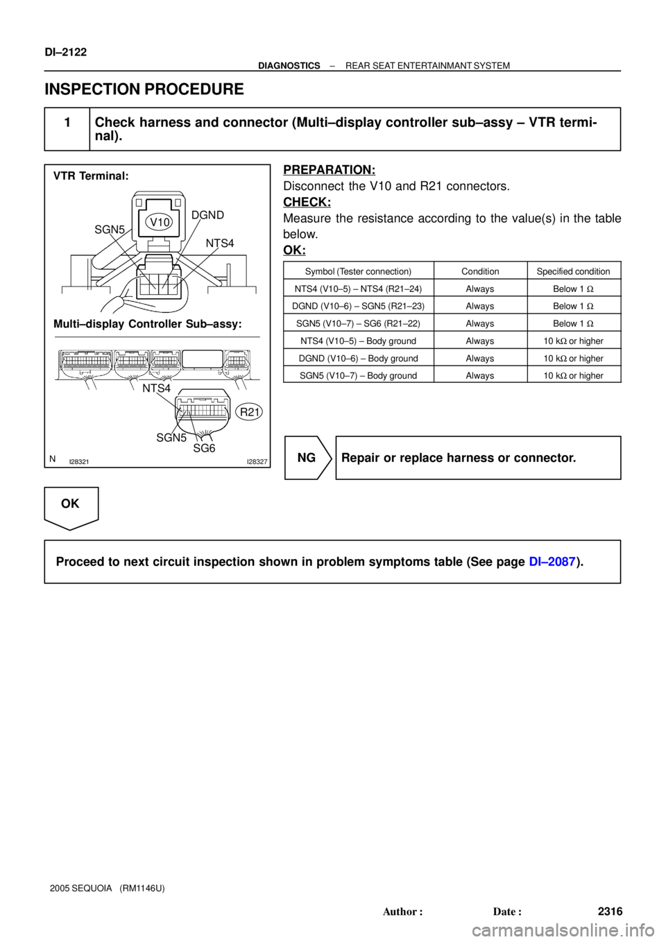
INSPECTION PROCEDURE
1 Check harness and connector (Multi±display controller sub±assy ± VTR termi-
nal).
PREPARATION:
Disconnect the V10 and R21 connectors.
CHECK:
Measure the resistance according to the value(s) in the table
below.
OK:
Symbol (Tester connection)ConditionSpecified condition
NTS4 (V10±5) ± NTS4 (R21±24)AlwaysBelow 1 W
DGND (V10±6) ± SGN5 (R21±23)AlwaysBelow 1 W
SGN5 (V10±7) ± SG6 (R21±22)AlwaysBelow 1 W
NTS4 (V10±5) ± Body groundAlways10 kW or higher
DGND (V10±6) ± Body groundAlways10 kW or higher
SGN5 (V10±7) ± Body groundAlways10 kW or higher
NG Repair or replace harness or connector.
OK
Proceed to next circuit inspection shown in problem symptoms table (See page DI±2087).
Page 2333 of 4323
I28666
Multi±display
Controller Sub±assy
R2112
R2111
R2110 BR
BR AUXR
AUXL
SG61
2
3
(Shielded) V10
VTR Terminal
AUXR
AUXL
SG7
± DIAGNOSTICSREAR SEAT ENTERTAINMANT SYSTEM
DI±2131
2325 Author�: Date�:
2005 SEQUOIA (RM1146U)
Sound signal circuit (Multi±display controller sub±assy ± VTR ter-
minal)
CIRCUIT DESCRIPTION
This is the sound signal circuit from the VTR terminal to the multi±display controller sub±assy.
WIRING DIAGRAM
DIDBF±01
Page 2334 of 4323
I28321I28327
VTR Terminal:
Multi±display Controller Sub±assy:SG6
V10
R21
AUXL
AUXR
AUXR
AUXL
SG7
DI±2132
± DIAGNOSTICSREAR SEAT ENTERTAINMANT SYSTEM
2326 Author�: Date�:
2005 SEQUOIA (RM1146U)
INSPECTION PROCEDURE
1 Check harness and connector (VTR terminal ± Multi±display controller sub±
assy).
PREPARATION:
Disconnect the R21 and V10 connectors.
CHECK:
Measure the resistance according to the value(s) in the table
below.
OK:
Symbol (Tester connection)ConditionSpecified condition
SG6 (V10±3) ± SG7 (R21±10)AlwaysBelow 1 W
AUXR (V10±1) ± AUXR (R21±12)AlwaysBelow 1 W
AUXL (V10±2) ± AUXL (R21±11)AlwaysBelow 1 W
AUXR (V10±1) ± Body groundAlways10 kW or higher
AUXL (V10±2) ± Body groundAlways10 kW or higher
SG6 (V10±3) ± Body groundAlways10 kW or higher
NG Repair or replace harness or connector.
OK
Proceed to next circuit inspection shown in problem symptoms table (See page DI±2087).