Page 2335 of 4323
I28668
HP1R
HP1L
SG5 R219
R218
R217 BR
BR HPR
HPL
SGND1
2
3
(Shielded) H10
Headphone Terminal LHMulti±display
Controller Sub±assy
HP2R
HP2L
SG6 R2121
R2120
R2119 BR
BR HPR
HPL
SGND1
2
3
(Shielded) H11
Headphone Terminal RH
± DIAGNOSTICSREAR SEAT ENTERTAINMANT SYSTEM
DI±2133
2327 Author�: Date�:
2005 SEQUOIA (RM1146U)
Sound signal circuit (Multi±display controller sub±assy ± Head-
phone terminal)
CIRCUIT DESCRIPTION
This is the sound signal circuit from the headphone terminal to the multi±display controller sub±assy.
WIRING DIAGRAM
DIDBG±01
Page 2336 of 4323

I28333
Headphone Terminal:
Multi±display Controller Sub±assy:
SG5HP1L
HP1R
SG6
HP2L HP2R R21
H10
H11
HPR
HPL
SGND
DI±2134
± DIAGNOSTICSREAR SEAT ENTERTAINMANT SYSTEM
2328 Author�: Date�:
2005 SEQUOIA (RM1146U)
INSPECTION PROCEDURE
1 Check harness and connector (Headphone terminal ± Multi±display controller
sub±assy).
PREPARATION:
Disconnect the H10 (H11) and R21 connectors.
CHECK:
Measure the resistance according to the value(s) in the table
below.
OK:
Symbol (Tester connection)ConditionSpecified condition
HPR (H10±1) ± HP1R (R21±9)AlwaysBelow 1 W
HPL (H10±2) ± HP1L (R21±8)AlwaysBelow 1 W
HPR (H11±1) ± HP2R (R21±21)AlwaysBelow 1 W
HPL (H11±2) ± HP2L (R21±20)AlwaysBelow 1 W
SGND (H10±3) ± SG5 (R21±7)AlwaysBelow 1 W
SGND (H11±3) ± SG6 (R21±19)AlwaysBelow 1 W
HPR (H10±1, H11±1) ± Body groundAlways10 kW or higher
HPL (H10±2, H11±2) ± Body groundAlways10 kW or higher
SGND (H10±3, H11±3) ± Body groundAlways10 kW or higher
SGND (H10±3) ± Body groundAlways10 kW or higher
SGND (H11±3) ± Body groundAlways10 kW or higher
NG Repair or replace harness or connector.
OK
Proceed to next circuit inspection shown in problem symptoms table (See page DI±2087).
Page 2357 of 4323
I28495
Multi±display
Controller Sub±assy
LG3
GAUX R21
CE V10
VTR Terminal
4
± DIAGNOSTICSREAR SEAT ENTERTAINMANT SYSTEM
DI±2155
2349 Author�: Date�:
2005 SEQUOIA (RM1146U)
VTR terminal set signal circuit
CIRCUIT DESCRIPTION
When terminal GAUX is grounded, the multi±display controller recognizes that an external device is con-
nected.
WIRING DIAGRAM
DIDBM±01
Page 2358 of 4323
I28321I28327
VTR Terminal:
Multi±display Controller Sub±assy:
GAUX
CE
V10
R21
DI±2156
± DIAGNOSTICSREAR SEAT ENTERTAINMANT SYSTEM
2350 Author�: Date�:
2005 SEQUOIA (RM1146U)
INSPECTION PROCEDURE
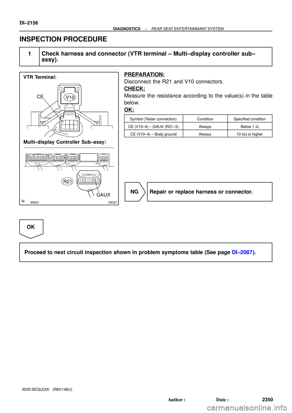
1 Check harness and connector (VTR terminal ± Multi±display controller sub±
assy).
PREPARATION:
Disconnect the R21 and V10 connectors.
CHECK:
Measure the resistance according to the value(s) in the table
below.
OK:
Symbol (Tester connection)ConditionSpecified condition
CE (V10±4) ± GAUX (R21±3)AlwaysBelow 1 W
CE (V10±4) ± Body groundAlways10 kW or higher
NG Repair or replace harness or connector.
OK
Proceed to next circuit inspection shown in problem symptoms table (See page DI±2087).
Page 2361 of 4323
DIDBO±01
± DIAGNOSTICSNAVIGATION SYSTEM
DI±2159
2353 Author�: Date�:
2005 SEQUOIA (RM1146U)
NAVIGATION SYSTEM
PRECAUTION
NOTICE:
When disconnecting the battery terminal, initialize the following system after the terminal is recon-
nected.
System NameSee Page
Back Door Power Window Control SystemBE±77
Page 2362 of 4323
DIDBP±01
I27727
Instrument Panel J/B
� RAD NO. 2 Fuse
� ECU±B Fuse
� AM1 FuseEngine Room J/B
� RAD NO. 1 Fuse
� RAD NO. 3 Fuse
Steering Pad
Switch
Ignition SwitchDisc Player
Controller
(*1)
Stereo
Component
Amplifier
Multi±display
Controller (*1)
VTR
Terminal
(*1)Headphone
Terminal
(*1) (*2)
Radio and
Navigation Assy GPS Antenna
TweeterTelevision Display Assy (*1)
Rear Seat Audio
Controller Assy (*2)
Rear Door SpeakerRear Door Speaker
Front Door Speaker
and Woofer
Front Door Speaker
and Woofer
*1: w/ RSE System
*2: w/ RSA System
DI±2160
± DIAGNOSTICSNAVIGATION SYSTEM
2354 Author�: Date�:
2005 SEQUOIA (RM1146U)
LOCATION
Page 2374 of 4323

DIDBS±01
Vehicle brought into a workshop
1. Diagnostic questioning and symptom confirmation
HINT:
Ask the customer about symptoms and confirm malfunctions.
Fill out the Customer Problem Analysis check sheet.
The screen displays nothing (Go to step 5, proceed
to ºBLACK SCREEN (NO IMAGE APPEARS ON
NAVIGATION/AUDIO SCREEN)º) P. DI±2214 Other symptoms
2. Confirm the system normal condition
P. DI±2162Applicable (This is not a malfunction.)
Not applicable
3. Check the diagnostic trouble codes
HINT:
� Even if the malfunction symptom is not confirmed, check the diagnostic trouble codes.
This is because the system stores past diagnostic trouble codes.
� Refer to the detailed description on the diagnostic screen, as necessary. A code is outputA code is not output (Go to step 5)
4. Diagnostic trouble code chart.
HINT:
Find the output code on the diagnostic trouble code chart.Output the diagnostic trouble code (Go to step 7)
5. Problem symptoms table
HINT:
If the symptom does not recur and no code is output,
perform the symptom reproduction method.There is an applicable symptom code in the table
(Go to step 7)
There is no applicable
symptom code in the
table
6. Check the ECU terminal arrangement based on the malfunction symptom
7. Circuit inspection and part inspection
8. Recheck the diagnostic trouble code
HINT:
After deleting the DTC, recheck the diagnostic trouble code.
9. Perform confirmation test
ENDItems inside
are titles of pages in this manual,
with the page number in the bottom portion. See
the pages for detailed explanations.
P. DI±2191
P. DI±2214 ± DI±2294 P. DI±2203
P. DI±2184
P. DI±2199
DI±2172
± DIAGNOSTICSNAVIGATION SYSTEM
2366 Author�: Date�:
2005 SEQUOIA (RM1146U)
HOW TO PROCEED WITH TROUBLESHOOTING
Page 2389 of 4323

TERMINALS OF ECU
1. RADIO AND NAVIGATION ASSY
Symbols (Terminal No.)Wiring Col")
DIDC4±01
I28763
R27
R29R30
R26R28
± DIAGNOSTICSNAVIGATION SYSTEM
DI±2187
2381 Author�: Date�:
2005 SEQUOIA (RM1146U)
TERMINALS OF ECU
1. RADIO AND NAVIGATION ASSY
Symbols (Terminal No.)Wiring ColorTerminal DescriptionConditionSpecification
ACC (R30±11) ±
GND (R30±20)GR ± BRAccessory (ON)Ignition switch OFF
"ACC or ONBelow 1 V "10 to 14 V
B (R30±1) ± GND (R30±20)L±Y ± BRBatteryAlways10 to 14 V
GND (R30±20) ± Body groundBR ±
Body groundGroundAlwaysBelow 1 V
ANT (R30±13) ±
GND (R30±20)B±R ± BRPower source of antennaRadio switch ON and AM or FM10 to 14 V
ILL+ (R30±2) ± ILL± (R30±12)G ± W±GIllumination signal
Ignition switch ON
Light control switch OFF "TAIL or
ONBelow 1 V "
10 to 14 V
R+ (R30±8) ± GND (R30±20)W ± BRSound signal (Right)Audio system is playing
A waveform synchro-
nized with sound is out-
put
L+ (R30±9) ± GND (R30±20)B ± BRSound signal (Left)Audio system is playing
A waveform synchro-
nized with sound is out-
put
R± (R30±18) ± GND (R30±20)G ± BRSound signal (Right)Audio system is playing
A waveform synchro-
nized with sound is out-
put
L± (R30±19) ± GND (R30±20)R ± BRSound signal (Left)Audio system is playing
A waveform synchro-
nized with sound is out-
put
SWG (R27±6) ± Body groundBR±W ±
Body groundSteering pad switch
groundAlwaysBelow 1 V
SW1 (R27±7) ± SWG (R27±6)LG±R ± BR±WSteering pad switch signal
Steering pad switch not operated
"SEEK+ switch pushed
"SEEK± switch pushed
"VOL+ switch pushed
"VOL± switch pushed4 V or more
"Approx. 0.5 V
"Approx. 0.9 V
"Approx. 2.0 V
"Approx. 3.4 V
 H10
Headphone Terminal LHMulti±display
Controller Sub±assy
HP2R
HP2L
SG6 R2121
R2120
R2119 BR
BR HPR
HPL
SGND1
2
3
(Shielded)")