Page 3353 of 4323
H24333
H24334ClawClip
H24316
H24337
H24861
RS±62
± SUPPLEMENTAL RESTRAINT SYSTEMSIDE AIRBAG ASSEMBLY (Manual Adjuster Type)
3345 Author�: Date�:
2005 SEQUOIA (RM1146U)
(b) Remove the 2 screws and vertical adjuster handle.
9. REMOVE SEAT CUSHION INNER SHIELD
(a) Remove the screw from the seat cushion inner shield.
(b) Using a screwdriver, remove the seat cushion inner
shield.
HINT:
Tape the screwdriver tip before use.
10. REMOVE FRONT SEAT INNER BELT
(a) Disconnect the wire harness clamps and connectors.
(b) Remove the nut and front seat inner belt.
11. REMOVE ARMREST ASSEMBLY
(a) Using a screwdriver, remove the armrest cap.
(b) Remove the bolt, armrest spacer, armrest lock plate and
armrest assembly.
(c) Remove the spacer from the armrest assembly.
12. REMOVE SEATBACK COVER AND PAD
(a) Remove the hog rings from the seat frame assembly.
(b) Open the fastener.
(c) w/ Side airbag:
Remove the nut and disconnect the seatback cover
bracket from the seat frame assembly.
Page 3354 of 4323
H24338Hog Ring
H24339Hog Ring
H24319
± SUPPLEMENTAL RESTRAINT SYSTEMSIDE AIRBAG ASSEMBLY (Manual Adjuster Type)
RS±63
3346 Author�: Date�:
2005 SEQUOIA (RM1146U)
(d) Remove the hog rings shown in the illustration from the
seat frame assembly.
(e) Remove the hog rings from the seat frame assembly.
(f) Remove the seatback cover and pad from the seat frame
assembly.
13. REMOVE SEATBACK COVER
(a) Turn up the seatback cover and remove the hog rings.
(b) Remove the 2 headrest supports.
(c) Remove the seatback cover from the seatback pad.
Page 3355 of 4323

RS0LH±05
H16230
Cross Section
H23933
RS±64
± SUPPLEMENTAL RESTRAINT SYSTEMSIDE AIRBAG ASSEMBLY (Manual Adjuster Type)
3347 Author�: Date�:
2005 SEQUOIA (RM1146U)
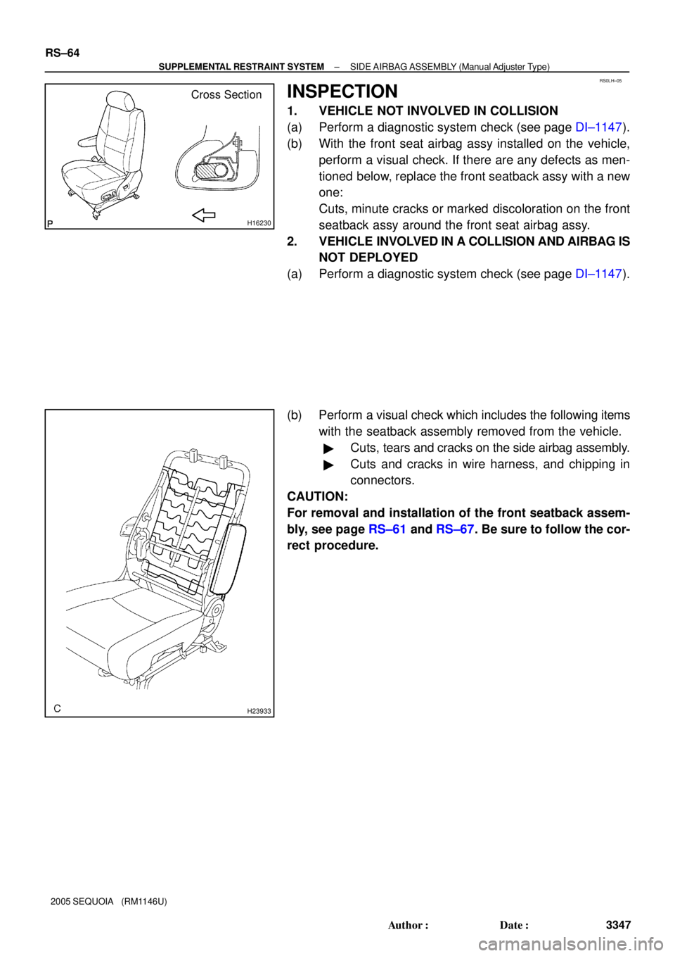
INSPECTION
1. VEHICLE NOT INVOLVED IN COLLISION
(a) Perform a diagnostic system check (see page DI±1147).
(b) With the front seat airbag assy installed on the vehicle,
perform a visual check. If there are any defects as men-
tioned below, replace the front seatback assy with a new
one:
Cuts, minute cracks or marked discoloration on the front
seatback assy around the front seat airbag assy.
2. VEHICLE INVOLVED IN A COLLISION AND AIRBAG IS
NOT DEPLOYED
(a) Perform a diagnostic system check (see page DI±1147).
(b) Perform a visual check which includes the following items
with the seatback assembly removed from the vehicle.
�Cuts, tears and cracks on the side airbag assembly.
�Cuts and cracks in wire harness, and chipping in
connectors.
CAUTION:
For removal and installation of the front seatback assem-
bly, see page RS±61 and RS±67. Be sure to follow the cor-
rect procedure.
Page 3357 of 4323

RS0LJ±03
RS±66
± SUPPLEMENTAL RESTRAINT SYSTEMSIDE AIRBAG ASSEMBLY (Manual Adjuster Type)
3349 Author�: Date�:
2005 SEQUOIA (RM1146U)
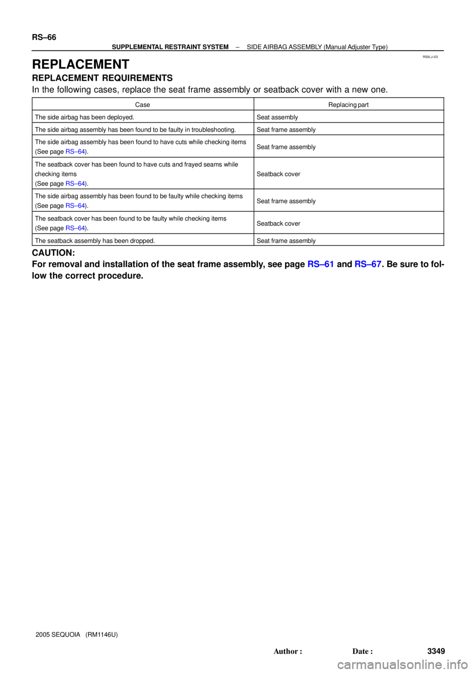
REPLACEMENT
REPLACEMENT REQUIREMENTS
In the following cases, replace the seat frame assembly or seatback cover with a new one.
CaseReplacing part
The side airbag has been deployed.Seat assembly
The side airbag assembly has been found to be faulty in troubleshooting.Seat frame assembly
The side airbag assembly has been found to have cuts while checking items
(See page RS±64).Seat frame assembly
The seatback cover has been found to have cuts and frayed seams while
checking items
(See page RS±64).
Seatback cover
The side airbag assembly has been found to be faulty while checking items
(See page RS±64).Seat frame assembly
The seatback cover has been found to be faulty while checking items
(See page RS±64).Seatback cover
The seatback assembly has been dropped.Seat frame assembly
CAUTION:
For removal and installation of the seat frame assembly, see page RS±61 and RS±67. Be sure to fol-
low the correct procedure.
Page 3358 of 4323

RS11E±01
H24319
H24339
H24338Hog Ring
± SUPPLEMENTAL RESTRAINT SYSTEMSIDE AIRBAG ASSEMBLY (Manual Adjuster Type)
RS±67
3350 Author�: Date�:
2005 SEQUOIA (RM1146U)
INSTALLATION
HINT:
�Use the same procedures for the RH side and LH side.
�The procedures listed below are for the LH side.
NOTICE:
�If the side airbag assembly has been dropped, or
there are cracks, dents or other defects in the case or
connector, replace the side airbag assembly with a
new one.
�When installing the side airbag assembly, take care
it is not pinched between other parts.
�Never use airbag parts from another vehicle. When
replacing parts, replace them with new ones.
1. INSTALL SEATBACK COVER
(a) Install the seatback cover to the seatback pad.
(b) Install the 2 headrest supports.
(c) Turn up the seatback cover and install the hog rings.
2. INSTALL SEATBACK COVER AND PAD
(a) Install the seatback cover and pad to the seat frame as-
sembly.
(b) Install the hog rings to the seat frame assembly.
(c) Install the hog rings to the seat frame assembly.
Page 3359 of 4323
H24861
H24337
H24316
H24334ClawClip RS±68
± SUPPLEMENTAL RESTRAINT SYSTEMSIDE AIRBAG ASSEMBLY (Manual Adjuster Type)
3351 Author�: Date�:
2005 SEQUOIA (RM1146U)
(d) w/ Side airbag:
Connect the seatback cover bracket to the seat frame as-
sembly with the nut.
Torque: 5.5 N´m (56 kgf´cm, 49 in.´lbf)
(e) Close the fastener.
(f) Install the hog rings to the seat frame assembly.
3. INSTALL ARMREST ASSEMBLY
(a) Install the spacer to the armrest assembly.
(b) Install the armrest assembly, armrest lock plate and arm-
rest spacer with the bolt.
Torque: 37 N´m (377 kgf´cm, 27 ft´lbf)
HINT:
Install the armrest lock plate as shown in the illustration.
(c) Install the armrest cap.
4. INSTALL FRONT SEAT INNER BELT
(a) Install the front seat inner belt with the nut.
Torque: 42 N´m (428 kgf´cm, 31 ft´lbf)
(b) Connect the connectors and wire harness clamps.
5. INSTALL SEAT CUSHION INNER SHIELD
Install the seat cushion inner shield with the screw.
Page 3422 of 4323

BE±10
± BODY ELECTRICALTROUBLESHOOTING
3414 Author�: Date�:
2005 SEQUOIA (RM1146U) Some of the system does not operate.
(Taillight does not come on.)
1. TAIL Fuse
2. TAILLIGHT Relay
3. Light Control Switch
4. Wire Harness
5. Body ECUBE±14
BE±27
BE±27
±
±
Some of the system do not operate.
(Theft deterrent horn or vehicle horn does not sound.)
1. HORN Fuse
2. SECURITY HORN Fuse
3. HORN Relay Circuit
4. Theft Deterrent Horn Circuit
5. Horn
6. Body ECUBE±14
BE±14
BE±145
BE±92
BE±145
±
While the warning is given, the system cannot be canceled by
unlocking the door with a key or transmitter.
1. Door Key Lock and Unlock Switch Circuit (Driver Door
ECU)
Door Key Lock and Unlock Switch Circuit (Passenger
Door ECU)
Door Key Lock and Unlock Switch Circuit (Back Door
ECU)
2. Body ECUDI±1794
DI±1832
DI±1882
±
*1: w/ Glass breakage sensor
WIRELESS DOOR LOCK CONTROL SYSTEM
This system uses the multiplex communication system, so check diagnosis system of the multiplex commu-
nication system before you proceed with troubleshooting.
HINT:
�Troubleshooting of the wireless door lock control system is based on the premise that the door lock
control system operates normally. Accordingly, before troubleshooting the wireless door lock control
system, first make certain that the door lock control system operates normally.
�If the trouble still reappears even though there are no abnormalities in any of the other circuits, check
and replace the Wireless Door Lock Control Receiver as the last step.
SymptomSuspect AreaSee page
All functions of wireless door lock control system do not operate.
1. Transmitter
2. Wireless Door Lock Control Receiver Circuit
3. Body ECUBE±98
DI±1737
±
Wireless door lock operates, but the buzzer does not sound.
(The buzzer does not sound when the customize function prohib-
its.)1. Wireless Door Lock Buzzer Circuit
2. Body ECUDI±1741
±
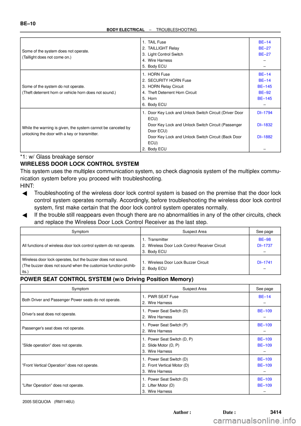
POWER SEAT CONTROL SYSTEM (w/o Driving Position Memory)
SymptomSuspect AreaSee page
Both Driver and Passenger Power seats do not operate.1. PWR SEAT Fuse
2. Wire HarnessBE±14
±
Driver's seat does not operate.1. Power Seat Switch (D)
2. Wire HarnessBE±109
±
Passenger's seat does not operate.1. Power Seat Switch (P)
2. Wire HarnessBE±109
±
ºSlide operationº does not operate.
1. Power Seat Switch (D, P)
2. Slide Motor (D, P)
3. Wire HarnessBE±109
BE±109
±
ºFront Vertical Operationº does not operate.
1. Power Seat Switch (D)
2. Front Vertical Motor (D)
3. Wire HarnessBE±109
BE±109
±
ºLifter Operationº does not operate.
1. Power Seat Switch (D)
2. Lifter Motor (D)
3. Wire HarnessBE±109
BE±109
±
Page 3428 of 4323
I18638
A. Taillight Relay Instrument Panel J/B:
Relays:
B. Back±Up Light Relay
C. ACC Relay
D. Power Main Relay
E. Fog Light Relay
F. MIRROR HEATER Relay
G. FLASHER Relay
H. SEAT HEATER Relay
Fuses:
1. TAIL Fuse
2. PWR No. 4 Fuse
3. PANEL Fuse
4. ECU±IG Fuse
123
4567
89
1011
12
1314
A
BC
DE
GH
F
15
1617 18 19
20
21 22 23
2425
265. CIG Fuse
6. PWR No. 1 Fuse
7. HTR Fuse
8. WSH Fuse
9. RAD No. 2 Fuse
10. WIP Fuse
11. FOG Fuse
12. AC INV Fuse 15 A
13. 4WD Fuse14. IGN1 Fuse
15. GAUGE Fuse
16. IGN 2 Fuse
17. STOP Fuse
18. SUN ROOF Fuse
19. PWR OUTLET Fuse
20. PWR No. 3 Fuse
21. OBD Fuse
22. PWR No. 2 Fuse
23. SEAT HTR Fuse
24. PWR SEAT Fuse
25. AM1 Fuse
26. PWR No. 5 Fuse 15 A 10 A
20 A
7.5 A
10 A
15 A
25 A
10 A
25 A
7.5 A
25 A
15 A
20 A15 A
20 A
15 A
25 A
15 A
20 A
7.5 A
25 A
15 A
30 A
40 A
30 A BE±16
± BODY ELECTRICALPOWER SOURCE
3420 Author�: Date�:
2005 SEQUOIA (RM1146U)