Page 2107 of 4323

DI3IR±10
± DIAGNOSTICSMULTIPLEX COMMUNICATION SYSTEM
DI±1905
2099 Author�: Date�:
2005 SEQUOIA (RM1146U)
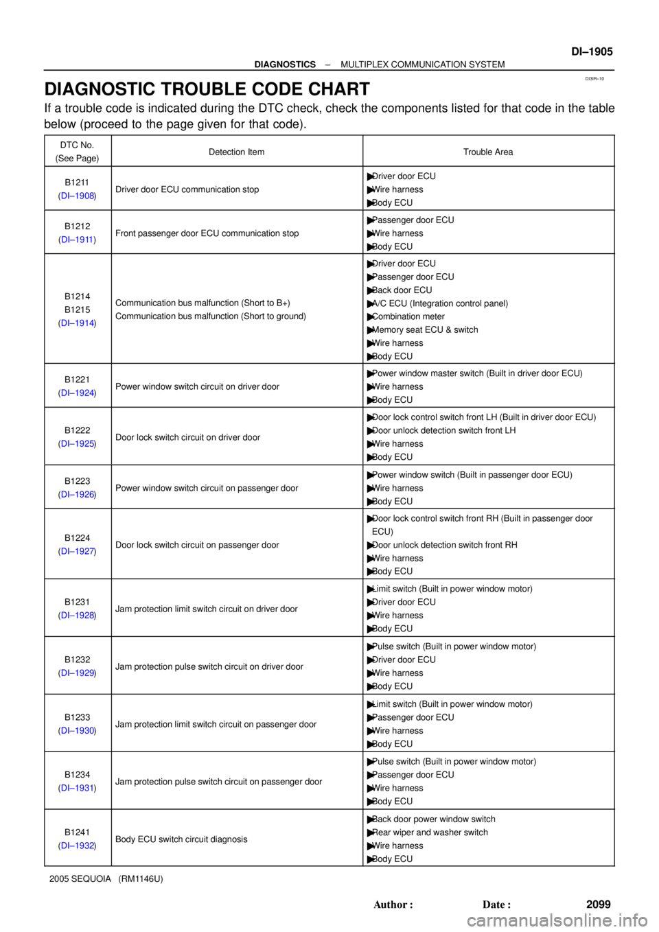
DIAGNOSTIC TROUBLE CODE CHART
If a trouble code is indicated during the DTC check, check the components listed for that code in the table
below (proceed to the page given for that code).
DTC No.
(See Page)Detection ItemTrouble Area
B1211
(DI±1908)Driver door ECU communication stop
�Driver door ECU
�Wire harness
�Body ECU
B1212
(DI±1911)Front passenger door ECU communication stop
�Passenger door ECU
�Wire harness
�Body ECU
B1214
B1215
(DI±1914)Communication bus malfunction (Short to B+)
Communication bus malfunction (Short to ground)
�Driver door ECU
�Passenger door ECU
�Back door ECU
�A/C ECU (Integration control panel)
�Combination meter
�Memory seat ECU & switch
�Wire harness
�Body ECU
B1221
(DI±1924)Power window switch circuit on driver door
�Power window master switch (Built in driver door ECU)
�Wire harness
�Body ECU
B1222
(DI±1925)Door lock switch circuit on driver door
�Door lock control switch front LH (Built in driver door ECU)
�Door unlock detection switch front LH
�Wire harness
�Body ECU
B1223
(DI±1926)Power window switch circuit on passenger door
�Power window switch (Built in passenger door ECU)
�Wire harness
�Body ECU
B1224
(DI±1927)Door lock switch circuit on passenger door
�Door lock control switch front RH (Built in passenger door
ECU)
�Door unlock detection switch front RH
�Wire harness
�Body ECU
B1231
(DI±1928)Jam protection limit switch circuit on driver door
�Limit switch (Built in power window motor)
�Driver door ECU
�Wire harness
�Body ECU
B1232
(DI±1929)Jam protection pulse switch circuit on driver door
�Pulse switch (Built in power window motor)
�Driver door ECU
�Wire harness
�Body ECU
B1233
(DI±1930)Jam protection limit switch circuit on passenger door
�Limit switch (Built in power window motor)
�Passenger door ECU
�Wire harness
�Body ECU
B1234
(DI±1931)Jam protection pulse switch circuit on passenger door
�Pulse switch (Built in power window motor)
�Passenger door ECU
�Wire harness
�Body ECU
B1241
(DI±1932)Body ECU switch circuit diagnosis
�Back door power window switch
�Rear wiper and washer switch
�Wire harness
�Body ECU
Page 2108 of 4323

DI±1906
± DIAGNOSTICSMULTIPLEX COMMUNICATION SYSTEM
2100 Author�: Date�:
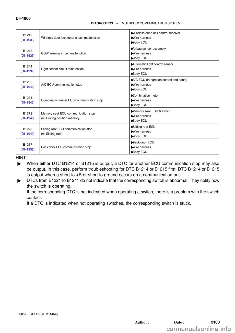
2005 SEQUOIA (RM1146U)B1242
(DI±1933)
Wireless door lock tuner circuit malfunction
�Wireless door lock control receiver
�Wire harness
�Body ECU
B1243
(DI±1935)GSW terminal circuit malfunction
�Airbag sensor assembly
�Wire harness
�Body ECU
B1244
(DI±1937)Light sensor circuit malfunction
�Automatic light control sensor
�Wire harness
�Body ECU
B1262
(DI±1940)A/C ECU communication stop
�A/C ECU (Integration control and panel)
�Wire harness
�Body ECU
B1271
(DI±1943)Combination meter ECU communication stop
�Combination meter
�Wire harness
�Body ECU
B1272
(DI±1946)Memory seat ECU communication stop
(w/ Driving position memory)�Memory seat ECU & switch
�Wire harness
�Body ECU
B1273
(DI±1949)Sliding roof ECU communication stop
(w/ Sliding roof)�Sliding roof ECU
�Wire harness
�Body ECU
B1287
(DI±1952)Back door ECU communication stop
�Back door ECU
�Wire harness
�Body ECU
HINT:
�When either DTC B1214 or B1215 is output, a DTC for another ECU communication stop may also
be output. In this case, perform troubleshooting for DTC B1214 or B1215 first. DTC B1214 or B1215
is output when a short to +B or short to ground occurs on a communication bus.
�DTCs from B1221 to B1241 do not indicate that the corresponding switch is abnormal. They notify how
the switch is operating.
If the corresponding DTC is not indicated when operating a switch, there is a problem with the switch
contact.
If a DTC is indicated when not operating switches, the corresponding switch is stuck.
Page 2109 of 4323
DI3IS±11
I27730
Instrument Panel J/B
Passenger Door ECU
(Power Window Switch) Combination Meter
Sliding Roof ECUDLC3 Body ECU
(Located behind
the instrument panel)
Driver Door ECU
(Power Window
Master Switch)
Back Door ECU
(Located inside the back door trim board) Automatic Light Control Sensor
Memory Seat ECU
& SwitchAirbag
Sensor
Assy
Power Window
Motor Front RH
� Limit Switch
� Pulse Switch Power Window
Motor Front LH
� Limit Switch
� Pulse Switch
A/C ECU
(Integration Control and Panel)
± DIAGNOSTICSMULTIPLEX COMMUNICATION SYSTEM
DI±1907
2101 Author�: Date�:
2005 SEQUOIA (RM1146U)
PARTS LOCATION
Page 2116 of 4323
DI±1914
± DIAGNOSTICSMULTIPLEX COMMUNICATION SYSTEM
2108 Author�: Date�:
2005 SEQUOIA (RM1146U)
DTC B1214 Communication bus malfunction
(Short to B+)
DTC B1215 Communication bus malfunction
(Short to ground)
CIRCUIT DESCRIPTION
DTC B1214 or B1215 is detected when a short to +B or short to ground occurs on the multiplex communica-
tion bus (BEAN). Detecting this condition will disable the multiplex communication bus (BEAN) and output
the corresponding DTC.
DTC NO.DTC detecting conditionTrouble area
B1214Short to B+ in multiplex communication system communica-
tion circuit
�Driver door ECU
�Passenger door ECU
�Back door ECU
�A/C ECU (Integration control panel)
�Combination meter
�Memory seat ECU & switch
�Wire harness
�Body ECU
B1215Short to ground in multiplex communication system commu-
nication circuit
�Driver door ECU
�Passenger door ECU
�Back door ECU
�A/C ECU (Integration control panel)
�Combination meter
�Memory seat ECU & switch
�Wire harness
�Body ECU
DI94Y±07
Page 2117 of 4323
I28465
D22
Driver Door ECU
S19
Sliding Roof
Control ECU
Combination MeterI19
A/C ECU
(Integration Control and Panel)
Memory Seat ECU
& SwitchBody ECU
J/C
Back Door ECU
F18
Passenger
Door ECUInstrument Panel J/B
J/CIB1
1M 1GB7
B7
B5
M6 C5
II2J33 J34 BI2
BD2 BF1
B11 C5
C5
B11 J33 J34
BD2 BF1 II2 J33 J34 IB1MPX1
MPX2 MPX3 MPX1MPX2
MPX1
MPX1
MPX2 MPX1
MPX2
MPX1MPX±MPX+ W±L
G±B
G±O
LG±B L±Y
LG±RWW±L
G±O
W
LG±RLG±R
BLG±R
BBB B B
A G H A
G W
(*2)
10
8 11 (*2)
21
14762 4
G±B171 3 1324 31
32
30 8(*3)
(*1)
(*1) (*1)(*3) 3
9
1220 22
8
20
2
G±B
(*1): w/ Driving Position Memory
(*2): w/o Driving Position Memory
(*3): w/ Sliding Roof 8 (*1)(*1)
20
± DIAGNOSTICSMULTIPLEX COMMUNICATION SYSTEM
DI±1915
2109 Author�: Date�:
2005 SEQUOIA (RM1146U)
WIRING DIAGRAM
Page 2124 of 4323

DI±1922
± DIAGNOSTICSMULTIPLEX COMMUNICATION SYSTEM
2116 Author�: Date�:
2005 SEQUOIA (RM1146U)
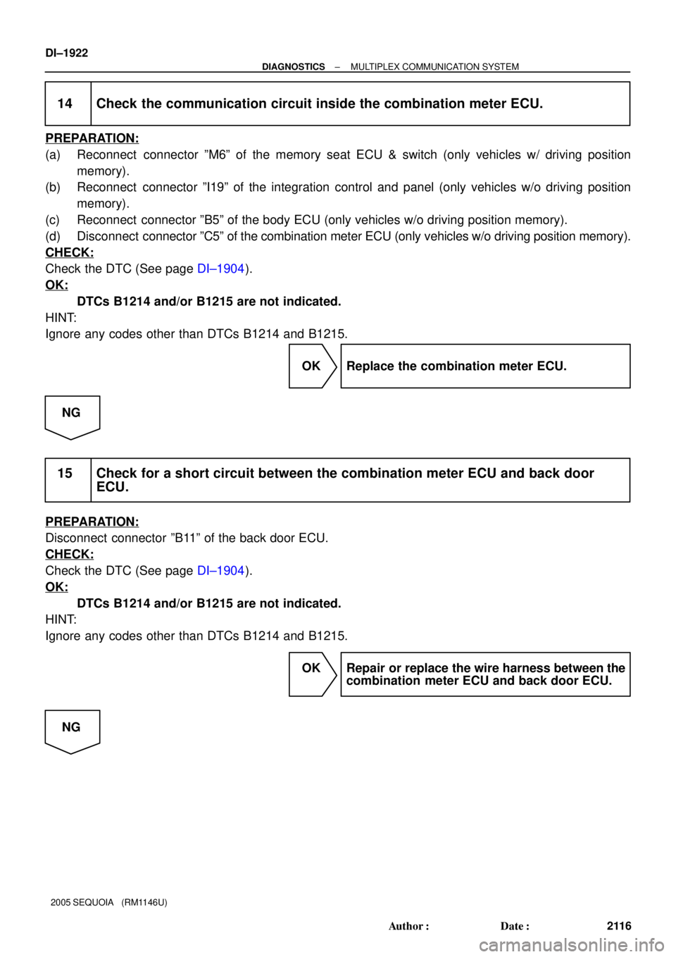
14 Check the communication circuit inside the combination meter ECU.
PREPARATION:
(a) Reconnect connector ºM6º of the memory seat ECU & switch (only vehicles w/ driving position
memory).
(b) Reconnect connector ºI19º of the integration control and panel (only vehicles w/o driving position
memory).
(c) Reconnect connector ºB5º of the body ECU (only vehicles w/o driving position memory).
(d) Disconnect connector ºC5º of the combination meter ECU (only vehicles w/o driving position memory).
CHECK:
Check the DTC (See page DI±1904).
OK:
DTCs B1214 and/or B1215 are not indicated.
HINT:
Ignore any codes other than DTCs B1214 and B1215.
OK Replace the combination meter ECU.
NG
15 Check for a short circuit between the combination meter ECU and back door
ECU.
PREPARATION:
Disconnect connector ºB11º of the back door ECU.
CHECK:
Check the DTC (See page DI±1904).
OK:
DTCs B1214 and/or B1215 are not indicated.
HINT:
Ignore any codes other than DTCs B1214 and B1215.
OK Repair or replace the wire harness between the
combination meter ECU and back door ECU.
NG
Page 2189 of 4323

± DIAGNOSTICSAUDIO SYSTEM
DI±1987
2181 Author�: Date�:
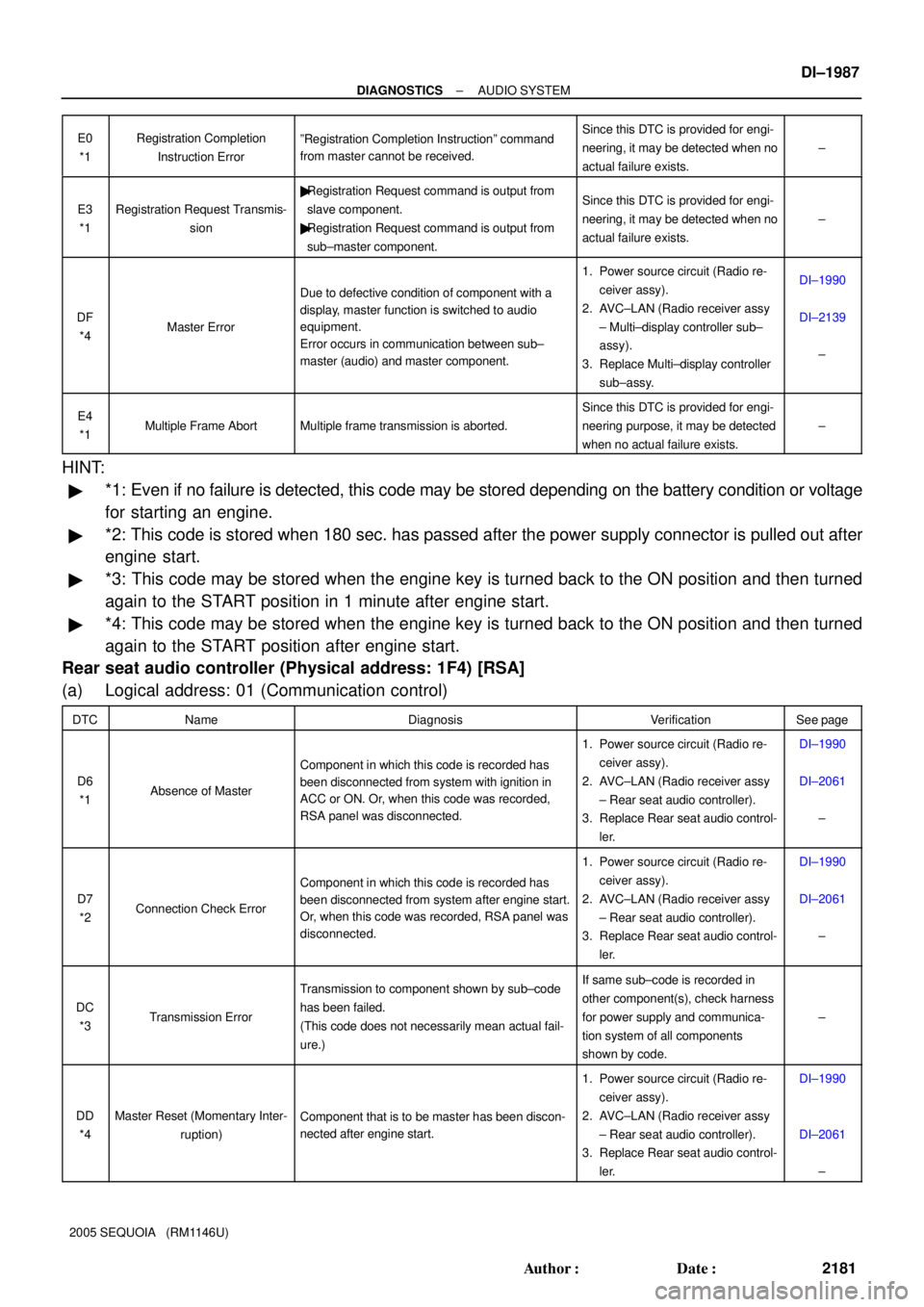
2005 SEQUOIA (RM1146U)E0
*1
Registration Completion
Instruction ErrorºRegistration Completion Instructionº command
from master cannot be received.Since this DTC is provided for engi-
neering, it may be detected when no
actual failure exists.
±
E3
*1Registration Request Transmis-
sion
�Registration Request command is output from
slave component.
�Registration Request command is output from
sub±master component.Since this DTC is provided for engi-
neering, it may be detected when no
actual failure exists.
±
DF
*4Master Error
Due to defective condition of component with a
display, master function is switched to audio
equipment.
Error occurs in communication between sub±
master (audio) and master component.
1. Power source circuit (Radio re-
ceiver assy).
2. AVC±LAN (Radio receiver assy
± Multi±display controller sub±
assy).
3. Replace Multi±display controller
sub±assy.DI±1990
DI±2139
±
E4
*1Multiple Frame AbortMultiple frame transmission is aborted.
Since this DTC is provided for engi-
neering purpose, it may be detected
when no actual failure exists.
±
HINT:
�*1: Even if no failure is detected, this code may be stored depending on the battery condition or voltage
for starting an engine.
�*2: This code is stored when 180 sec. has passed after the power supply connector is pulled out after
engine start.
�*3: This code may be stored when the engine key is turned back to the ON position and then turned
again to the START position in 1 minute after engine start.
�*4: This code may be stored when the engine key is turned back to the ON position and then turned
again to the START position after engine start.
Rear seat audio controller (Physical address: 1F4) [RSA]
(a) Logical address: 01 (Communication control)
DTCNameDiagnosisVerificationSee page
D6
*1Absence of Master
Component in which this code is recorded has
been disconnected from system with ignition in
ACC or ON. Or, when this code was recorded,
RSA panel was disconnected.
1. Power source circuit (Radio re-
ceiver assy).
2. AVC±LAN (Radio receiver assy
± Rear seat audio controller).
3. Replace Rear seat audio control-
ler.DI±1990
DI±2061
±
D7
*2Connection Check Error
Component in which this code is recorded has
been disconnected from system after engine start.
Or, when this code was recorded, RSA panel was
disconnected.
1. Power source circuit (Radio re-
ceiver assy).
2. AVC±LAN (Radio receiver assy
± Rear seat audio controller).
3. Replace Rear seat audio control-
ler.DI±1990
DI±2061
±
DC
*3Transmission Error
Transmission to component shown by sub±code
has been failed.
(This code does not necessarily mean actual fail-
ure.)If same sub±code is recorded in
other component(s), check harness
for power supply and communica-
tion system of all components
shown by code.
±
DD
*4Master Reset (Momentary Inter-
ruption)Component that is to be master has been discon-
nected after engine start.
1. Power source circuit (Radio re-
ceiver assy).
2. AVC±LAN (Radio receiver assy
± Rear seat audio controller).
3. Replace Rear seat audio control-
ler.DI±1990
DI±2061
±
Page 2246 of 4323
DIDAD±01
DI±2044
± DIAGNOSTICSREAR SEAT AUDIO SYSTEM
2238 Author�: Date�:
2005 SEQUOIA (RM1146U)
REAR SEAT AUDIO SYSTEM
PRECAUTION
NOTICE:
When disconnecting the battery terminal, initialize the following system after the terminal is recon-
nected.
System NameSee Page
Back Door Power Window Control SystemBE±77