Page 2949 of 4323
TR04I±06
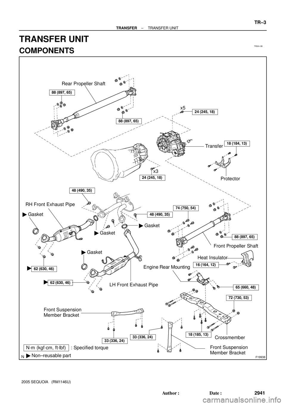
F19938
Rear Propeller Shaft
24 (245, 18)
24 (245, 18)
48 (490, 35)
48 (490, 35)
62 (630, 46)
88 (897, 65)
65 (660, 48)
Protector Transfer
� Gasket
� Gasket
� Gasket� Gasket RH Front Exhaust Pipe
LH Front Exhaust PipeFront Propeller Shaft
Engine Rear Mounting
Crossmember �
62 (630, 46)�
x5
x3
74 (750, 54)
72 (730, 53)
18 (185, 13)
N´m (kgf´cm, ft´lbf) : Specified torque
� Non±reusable part
Heat Insulator
16 (164, 12)
Front Suspension
Member Bracket
Front Suspension
Member Bracket
33 (336, 24)33 (336, 24)
88 (897, 65)
88 (897, 65)
18 (184, 13)
± TRANSFERTRANSFER UNIT
TR±3
2941 Author�: Date�:
2005 SEQUOIA (RM1146U)
TRANSFER UNIT
COMPONENTS
Page 2950 of 4323

REMOVAL
1. SWITCH TRANSFER TO 2WD
2. REMOVE PROTECTOR
Remove the 4 bolts and protector.
3. DRAIN TR")
TR0DD±01
F19315
F19237
TR±4
± TRANSFERTRANSFER UNIT
2942 Author�: Date�:
2005 SEQUOIA (RM1146U)
REMOVAL
1. SWITCH TRANSFER TO 2WD
2. REMOVE PROTECTOR
Remove the 4 bolts and protector.
3. DRAIN TRANSFER OIL
4. REMOVE FRONT SUSPENSION MEMBER BRACKET
Remove the 8 bolts and 2 front suspension member brackets.
5. REMOVE LH AND RH FRONT EXHAUST PIPES
(See page EM±126)
6. REMOVE FRONT AND REAR PROPELLER SHAFT
(See page PR±7)
7. REMOVE CROSS MEMBER
(a) Remove the 2 bolts and heat insulator.
(b) Support the rear side of the transmission with a transmis-
sion jack.
(c) Remove the 4 set bolts of the engine rear mounting.
(d) Remove the 4 bolts, nuts and cross member.
8. REMOVE ENGINE REAR MOUNTING
Remove the 4 bolts and engine rear mounting from the transfer.
9. DISCONNECT VEHICLE SPEED SENSOR AND
TRANSFER ACTUATOR CONNECTORS
10. REMOVE TRANSFER
(a) Support the transfer with another transmission jack.
(b) Remove the 8 transfer mounting bolts.
(c) Pull the transfer out from the transmission down and to-
ward the rear.
Page 2951 of 4323

± TRANSFERTRANSFER UNIT
TR±5
2943 Author�: Date�:
2005 SEQUOIA (RM1146U)
INSTALLATION
1. INSTALL TRANSFER
Raise the transfer and install it to t")
TR0DE±01
F19237
F19338
0 to 5 mm
(0 to 0.1968 in.)
± TRANSFERTRANSFER UNIT
TR±5
2943 Author�: Date�:
2005 SEQUOIA (RM1146U)
INSTALLATION
1. INSTALL TRANSFER
Raise the transfer and install it to the transmission with the 8
transfer mounting bolts.
Torque: 24 N´m (245 kgf´cm, 18 ft´lbf)
NOTICE:
Take care not to damage the lip of the transfer rear oil seal
with the transfer input shaft.
2. CONNECT VEHICLE SPEED SENSOR AND TRANS-
FER ACTUATOR CONNECTORS
3. INSTALL ENGINE REAR MOUNTING
Install the engine rear mounting to the transfer with the 4 bolts.
Torque: 65 N´m (660 kgf´cm, 48 ft´lbf)
4. INSTALL CROSS MEMBER
(a) Install the cross member with the 4 bolts and nuts.
Torque: 72 N´m (730 kgf´cm, 53 ft´lbf)
(b) Install the 4 set bolts of the engine rear mounting.
Torque: 18 N´m (185 kgf´cm, 13 ft´lbf)
(c) Remove the transmission jacks.
(d) Install the heat insulator with the 2 bolts.
Torque: 16 N´m (164 kgf´cm, 12 ft´lbf)
5. INSTALL FRONT AND REAR PROPELLER SHAFTS
(See page PR±9)
6. INSTALL LH AND RH FRONT EXHAUST PIPES
(See page EM±128)
7. INSTALL FRONT SUSPENSION MEMBER BRACKET
Install the 2 front suspension member brackets with the 8 bolts.
Torque: 33 N´m (336 kgf´cm, 24 ft´lbf)
8. FILL WITH TRANSFER OIL
(a) Remove the filler plug and gasket.
(b) Fill with transfer oil.
Oil grade: API GL±4 or GL±5
Viscosity: SAE 75W±90
Capacity: 1.4 liters (1.5 US qts, 1.2 lmp.qts)
NOTICE:
�When supplying oil, pour it slowly.
�Supply oil several times at several minute intervals.
HINT:
The oil level must be within 0 to 5 mm (0 to 0.1968 in.) down from
the lowest end of the hole for the filler plug.
(c) After leaving it for 5 minutes, check the oil level again.
(d) Install the filler plug with a new gasket.
Torque: 37 N´m (377 kgf´cm, 27 ft´lbf)
Page 2952 of 4323
F19315
TR±6
± TRANSFERTRANSFER UNIT
2944 Author�: Date�:
2005 SEQUOIA (RM1146U)
9. INSTALL PROTECTOR
Install the protector with the 4 bolts.
Torque: 18 N´m (184 kgf´cm, 13 ft´lbf)
10. DO ROAD TEST
Check for abnormal noise and smooth shifting.
Page 2953 of 4323
TR0CI±02
F19231
Low Planetary Ring Gear
x5Transfer
Case Cover
Output Shaft Front
Needle Roller Bearing
Oil Pump Gear
Magnet
118 (1,203, 87)
Thrust Bearing Race No. 1
N´m (kgf´cm, ft´lbf)
: Specified torque
� Non±reusable part
� Precoated partSnap Ring Case Plug
Breather Oil
Deflector
Front Output Shaft
Companion Flange
� � Compression Spring
Front Bearing
Retainer
Low Planetary Gear Bearing Low Planetary Gear
Input Gear Stopper
Planetary Carrier Washer
Oil Separator
7.5 (76, 66 in.´lbf)
Oil PumpSnap Ring
Transfer Front
Case
� Oil SealSpacer
Snap RingInput Shaft
Ball
Head Pin
� O±Ring
� Oil Seal� Oil Seal
18.6 (190, 14)
18 (184, 13)
11.5 (117, 8)
7.5 (76, 66 in.´lbf)
7.5 (76, 66 in.´lbf)
± TRANSFERTRANSFER ASSEMBLY
TR±7
2945 Author�: Date�:
2005 SEQUOIA (RM1146U)
TRANSFER ASSEMBLY
COMPONENTS
Page 2954 of 4323
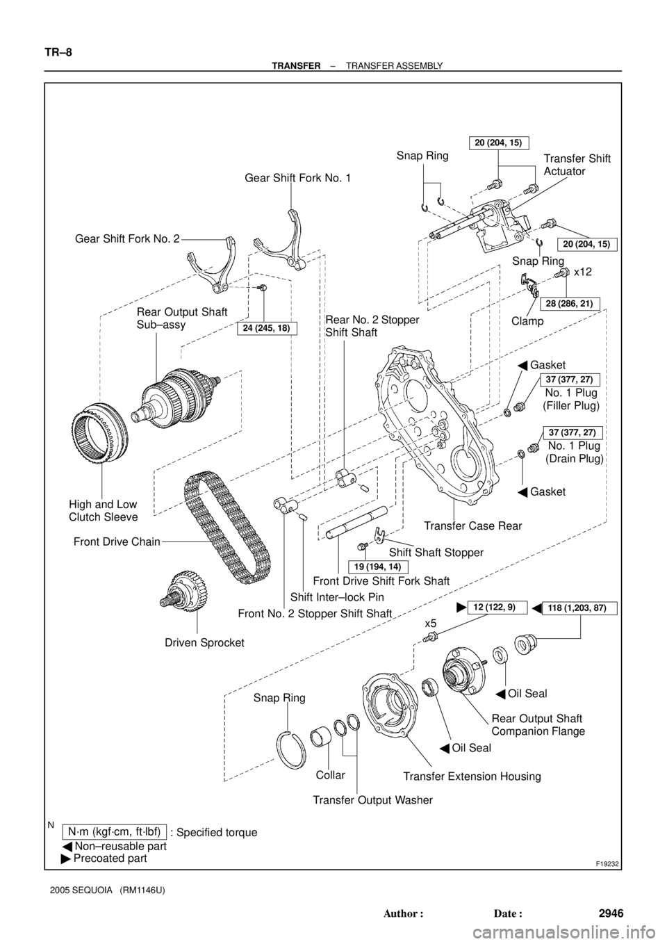
F19232
� �
N´m (kgf´cm, ft´lbf)
: Specified torque
� Non±reusable part
� Precoated partTransfer Extension Housing Collar Snap Ring
Transfer Output WasherRear Output Shaft
Companion Flange
24 (245, 18)
Driven Sprocket Front Drive Chain
19 (194, 14)
Shift Shaft Stopper Rear Output Shaft
Sub±assy
� Gasket
37 (377, 27)
(Filler Plug) Clamp
28 (286, 21)
x12
Gear Shift Fork No. 1
Rear No. 2 Stopper
Shift ShaftSnap RingTransfer Shift
Actuator
� Gasket
� Oil Seal High and Low
Clutch Sleeve
Gear Shift Fork No. 2
x5 Front No. 2 Stopper Shift ShaftShift Inter±lock PinFront Drive Shift Fork ShaftTransfer Case Rear Snap Ring20 (204, 15)
No. 1 Plug
37 (377, 27)
(Drain Plug) No. 1 Plug
� Oil Seal
12 (122, 9)
20 (204, 15)
118 (1,203, 87)
TR±8
± TRANSFERTRANSFER ASSEMBLY
2946 Author�: Date�:
2005 SEQUOIA (RM1146U)
Page 2955 of 4323

DISASSEMBLY
1. REMOVE FRONT BEARING RETAINER
(a) Remove the 5 bolts and f")
TR0DF±01
F19238
F19239
F19240
SST
F19241
SST
± TRANSFERTRANSFER ASSEMBLY
TR±9
2947 Author�: Date�:
2005 SEQUOIA (RM1146U)
DISASSEMBLY
1. REMOVE FRONT BEARING RETAINER
(a) Remove the 5 bolts and front bearing retainer.
HINT:
If necessary, tap on the front bearing retainer with a plastic ham-
mer to remove it.
(b) Using a screwdriver and hammer, remove the oil seal
from the front bearing retainer.
2. REMOVE TRANSFER CASE COVER
Remove the 4 bolts and transfer case cover.
3. REMOVE BREATHER OIL DEFLECTOR
4. REMOVE FRONT OUTPUT SHAFT COMPANION
FLANGE
(a) Using a chisel and hammer, loosen the staked part of the
front output shaft companion flange lock nut.
(b) Using SST to hold the front output shaft companion
flange, remove the output shaft companion flange lock
nut.
SST 09330±00021
(c) Using SST, remove the front output shaft companion
flange.
SST 09950±40011 (09951±04020, 09952±04010,
09953±04030, 09954±04010, 09955±04051,
09957±04010, 09958±04011)
(d) Using a screwdriver and hammer, remove the oil seal
from the front output shaft companion flange.
5. REMOVE REAR OUTPUT SHAFT COMPANION
FLANGE
Remove the rear output shaft companion flange in the same
way as the front output shaft companion flange.
Page 2956 of 4323

6. REMOVE TRANSFER EXTENSION HOUSING
(a) Remove the 5 bolts and transfer extension")
F19242
F19243
F19244
F19245
F19246
TR±10
± TRANSFERTRANSFER ASSEMBLY
2948 Author�: Date�:
2005 SEQUOIA (RM1146U)
6. REMOVE TRANSFER EXTENSION HOUSING
(a) Remove the 5 bolts and transfer extension housing.
HINT:
If necessary, tap on the transfer extension housing with a plas-
tic hammer to remove it.
(b) Using a screwdriver and hammer, remove the oil seal
from the transfer extension housing.
(c) Remove the 2 transfer output washers.
(d) Remove the collar.
7. REMOVE TRANSFER CASE REAR
(a) Remove the 12 bolts and clamp.
(b) Remove the transfer case rear.
HINT:
If necessary, tap on the transfer case rear with a plastic hammer
to remove it.
8. REMOVE GEAR SHIFT FORK NO. 2 AND HIGH AND
LOW CLUTCH SLEEVE
Remove the bolt, gear shift fork No.2 and high and low clutch
sleeve.
9. REMOVE SHIFT SHAFT STOPPER
Remove the bolt and shift shaft stopper.
10. REMOVE FRONT DRIVE SHIFT FORK SHAFT
(a) Turn the front drive shift fork shaft.
(b) Remove the front drive shift fork shaft from the rear case
aligning the cutout with the shift inter±lock pin.


Thrust Bearing Race No. 1
N´m (kgf´cm, ft´lbf)
: Specifi")