Page 2263 of 4323
I28599I28773
w/o Navigation:
Radio Receiver Assy
Rear Seat Audio Controller
R19
Stereo Component Amplifier AssyTX± TX+
S10 ID2
LG
LG
V
P L 9
10
5
R41522
R24
23
TX1± TX1+
TX± TX+27 26
TX± TX+ 20
19 R19
R4LGID2 R24
S10
± DIAGNOSTICSREAR SEAT AUDIO SYSTEM
DI±2061
2255 Author�: Date�:
2005 SEQUOIA (RM1146U)
AVC±LAN circuit
CIRCUIT DESCRIPTION
Each unit of the rear seat audio system connected to the AVC±LAN (communication bus) transfers the signal
of each switch by communication.
When a short to +B or short to ground occurs in this AVC± LAN, the audio system will not function normally
as communication is discontinued.
WIRING DIAGRAM
DIDAN±01
Page 2341 of 4323
9
10")
I28592
Multi±display
Controller Sub±assy R25
Television Display Assy
IF49
LG5
TX2+ ID217
R21
LG LG
IF410
LG4
TX2± ID218
R21
LG LG TX+
TX±
LG31
TX+
IF314
R23
L
LG30
TX± IF315
R23
LG TX+ (*1)9
10
9
10 � R27 (*1)
Radio and Navigation Assy
� R19 (*2)
Radio Receiver Assy
D23
Disc Player Controller
13
TX3± R22
LG
14
TX3+ R22 TX±
TX+18
17
LG
*1: w/ Navigation System
*2: w/o Navigation SystemTX1+ (*2)
TX± (*1)
TX1± (*2)
± DIAGNOSTICSREAR SEAT ENTERTAINMANT SYSTEM
DI±2139
2333 Author�: Date�:
2005 SEQUOIA (RM1146U)
AVC±LAN circuit
CIRCUIT DESCRIPTION
Each unit of this system connected to the AVC±LAN (communication bus) transfers the signal of each switch
by communication.
When a short to +B or short to ground occurs in this AVC± LAN, this system will not function normally as
communication is discontinued.
This system has 2 kinds of AVC±LAN: main AVC±LAN and sub AVC±LAN.
w/ navigation system:
In the main AVC±LAN, the radio and navigation assy becomes the communication master and has enough
resistance necessary for communication.
w/o navigation system:
In the main AVC±LAN, the radio receiver assy becomes the communication master and has enough resis-
tance necessary for communication.
In the sub AVC±LAN, the multi±display controller sub±assy becomes the communication master and has
enough resistance necessary for communication.
WIRING DIAGRAM
DIDBJ±01
Page 2470 of 4323
I28482
Stereo Component
Amplifier Assy
Radio and Navigation Assy
TX+
S10 R30V
P
TX±
S10ATX+
ATX± 20 5
19 15
R30 DI±2268
± DIAGNOSTICSNAVIGATION SYSTEM
2462 Author�: Date�:
2005 SEQUOIA (RM1146U)
AVC±LAN circuit (Radio and navigation assy ± stereo component
amplifier assy)
CIRCUIT DESCRIPTION
Each unit of the audio system connected to the AVC±LAN (communication bus) transfers the signal of each
switch by communication.
When a short to +B or short to ground occurs in this AVC± LAN, the audio system will not function normally
as communication is discontinued.
In this AVC±LAN, the radio and navigation assy becomes the master of the communication and the has re-
sistance necessary for communication.
WIRING DIAGRAM
DIDDH±01
Page 2677 of 4323
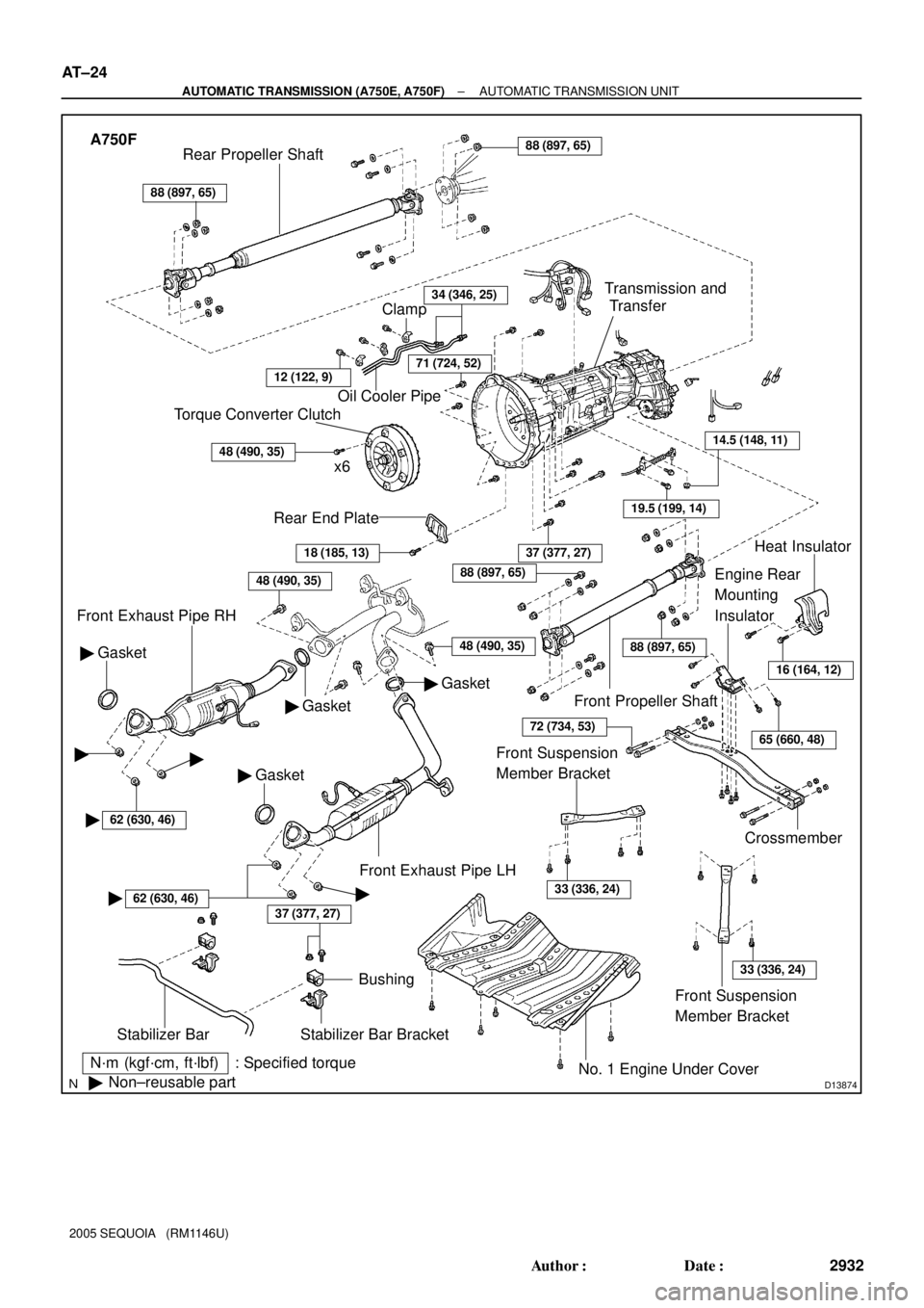
D13874
N´m (kgf´cm, ft´lbf) : Specified torque
�Non±reusable part
37 (377, 27)
Stabilizer Bar
Bushing
Stabilizer Bar Bracket
No. 1 Engine Under Cover
18 (185, 13)
Rear End Plate
Torque Converter Clutch
x 6
48 (490, 35)
Oil Cooler Pipe
34 (346, 25)
Gasket �
Front Exhaust Pipe RH
48 (490, 35)
Gasket �
� Gasket
37 (377, 27)
Crossmember
Engine Rear
Mounting
Insulator
19.5 (199, 14)
14.5 (148, 11)
Transmission and
Transfer
88 (897, 65)
Rear Propeller Shaft88 (897, 65)
Front Propeller Shaft
Heat Insulator
Front Exhaust Pipe LH
Clamp
71 (724, 52)
� Gasket
48 (490, 35)
16 (164, 12)
65 (660, 48)
88 (897, 65)
88 (897, 65)
72 (734, 53)
Front Suspension
Member Bracket
33 (336, 24)
Front Suspension
Member Bracket
33 (336, 24)
��
�62 (630, 46)
�62 (630, 46)�
12 (122, 9)
EM±90
± ENGINE MECHANICALENGINE UNIT (4WD)
2669 Author�: Date�:
2005 SEQUOIA (RM1146U)
Page 2940 of 4323
D13874
A750F
N´m (kgf´cm, ft´lbf) : Specified torque
�Non±reusable part
37 (377, 27)
Stabilizer Bar
Bushing
Stabilizer Bar Bracket
No. 1 Engine Under Cover
18 (185, 13)
Rear End Plate
Torque Converter Clutch
x6
48 (490, 35)
Oil Cooler Pipe
34 (346, 25)
Gasket �
Front Exhaust Pipe RH
Gasket �
� Gasket
37 (377, 27)
Crossmember
Engine Rear
Mounting
Insulator
19.5 (199, 14)
14.5 (148, 11)
Transmission and
Transfer
88 (897, 65)
Rear Propeller Shaft88 (897, 65)
Front Propeller Shaft
Heat Insulator
Front Exhaust Pipe LH
Clamp
71 (724, 52)
� Gasket
48 (490, 35)
16 (164, 12)
65 (660, 48)
88 (897, 65)
88 (897, 65)
72 (734, 53)
Front Suspension
Member Bracket
33 (336, 24)
Front Suspension
Member Bracket
33 (336, 24)
��
�62 (630, 46)
�62 (630, 46)�
12 (122, 9)
48 (490, 35)
AT±24
± AUTOMATIC TRANSMISSION (A750E, A750F)AUTOMATIC TRANSMISSION UNIT
2932 Author�: Date�:
2005 SEQUOIA (RM1146U)
Page 2944 of 4323
D13883
D14131
A750E:
A750F:
D14132
17 mm
Head17 mm Head
14 mm Head
AT±28
± AUTOMATIC TRANSMISSION (A750E, A750F)AUTOMATIC TRANSMISSION UNIT
2936 Author�: Date�:
2005 SEQUOIA (RM1146U)
17. REMOVE CROSSMEMBER
(a) Remove the 4 bolts of the engine rear mounting on the
crossmember.
Torque: 18 N´m (185 kgf´cm, 13 ft´lbf)
(b) Remove the 4 nuts, bolts, washers and crossmember.
Torque: 72 N´m (734 kgf´cm, 53 ft´lbf)
18. REMOVE ENGINE REAR MOUNTING INSULATOR
Remove the 4 bolts and engine rear mounting insulator.
Torque: 65 N´m (660 kgf´cm, 48 ft´lbf)
19. REMOVE TRANSMISSION
(a) A750E:
Separate the wire harness from the transmission.
(b) A750F:
Separate the wire harness from the transmission and
transfer.
(c) Lower the rear end of the transmission.
(d) Remove the 10 bolts and transmission.
Torque:
17 mm head: 71 N´m (720 kgf´cm, 53 ft´lbf)
14 mm head: 37 N´m (380 kgf´cm, 27 ft´lbf)
Page 2947 of 4323
TR04G±02
± TRANSFERTRANSFER SYSTEM
TR±1
2939 Author�: Date�:
2005 SEQUOIA (RM1146U)
TRANSFER SYSTEM
PRECAUTION
NOTICE:
When disconnecting the battery terminal, initialize the following system after the terminal is recon-
nected.
System NameSee Page
Back Door Power Window Control SystemBE±77
When working with FIPG material, you must observe the following:
�Using a razor blade and gasket scraper, remove all the old FIPG material from gasket surfaces.
�Thoroughly clean all components to remove any loose material.
�Clean both sealing surfaces with a non±residue solvent.
�Apply FIPG in an approx. 1.2 mm (0.047 in.) wide bead along the sealing surface.
�Parts must be assembled within 10 minutes of FIPG application. Otherwise, the FIPG material
must be removed and reapplied.
Page 2948 of 4323

TROUBLESHOOTING
PROBLEM SYMPTOMS TABLE
Use the table below to help find the cause of the problem. The numbers i")
TR04H±04
TR±2
± TRANSFERTROUBLESHOOTING
2940 Author�: Date�:
2005 SEQUOIA (RM1146U)
TROUBLESHOOTING
PROBLEM SYMPTOMS TABLE
Use the table below to help find the cause of the problem. The numbers indicate the priority of the likely cause
of the problem. Check each part in order. If necessary, replace these parts.
SymptomSuspected AreaSee page
Noise
1. Oil (Level low)
2. Oil (Wrong)
3. Transfer faultyTR±5
TR±5
TR±7
Oil leakage
1. Oil (Level too high)
2. Gasket (Damaged)
3. Oil seal (Worn or damaged)
4. O±ring (Worn or damaged)TR±5
TR±7
TR±16
TR±7
Tight corner brakingCenter differential or transfer faultyTR±7
Shift from 2WD (H) to 4WD (H) impossible
1. 4WD fuse
2. Wire harness
3. Vehicle speed sensor
4. 2WD/4HI switch
5. 4WD indicator light
6. Actuator assembly
7. A.D.D. control system
8. 4WD control ECU
9. Transfer assembly±
±
BE±55
TR±39
TR±39
TR±39
SA±61
TR±39
TR±3
Shift from 2WD (H) to 4WD (L4) impossible
1. 4LO switch
2. Wire harness
3. 4WD control ECUTR±39
±
TR±39
Shift from 4WD (H) to 4WD (L4) impossible
1. 4LO switch
2. Wire harness
3. 4WD control ECUTR±9
±
TR±39
Shift from 4WD (H) to 2WD (H) impossible
1. 4WD fuse
2. Wire harness
3. 4WD indicator light
4. Actuator assembly
5. A.D.D. control system
6. 4WD control ECU
7. Transfer assembly±
±
TR±39
TR±39
SA±61
TR±39
TR±3
Shift from 4WD (L4) to 2WD (H) impossible
1. 2WD/4HI switch
2. Wire harness
3. 4WD control ECUTR±39
±
TR±39
Shift from 4WD (L4) to 4WD (H) impossible
1. 2WD/4HI switch
2. Wire harness
3. 4WD control ECUTR±39
±
TR±39