Page 1778 of 4323

0.5")
DID51±01
A04550
CG
OP3
DLC3 12345678
9
1011
13 1516 12 14
TC
I28427
Security Indicator
Light MIL
BR3904
Normal System Code
0.25 Sec.0.25 Sec.
I02680
Diagnostic Trouble Code (Example Code 12, 99)
0.5 Sec. 0.5 Sec.
1.5 Sec. 2.5 Sec.
One Cycle4.5 Sec.Repeat
DI±1576
± DIAGNOSTICSENGINE IMMOBILISER SYSTEM
1770 Author�: Date�:
2005 SEQUOIA (RM1146U)
DTC CHECK / CLEAR
1. INSPECT DIAGNOSIS
(a) Check the DTC using SST check wire.
(1) Turn the ignition switch ON, but do not start the en-
gine.
(2) When checking DTC 99: Using SST, connect termi-
nals 13 (TC) and 4 (CG) of the DLC3.
(3) When checking codes except DTC 99: Using SST,
connect terminals 8 (OP3) and 4 (CG) of the DLC3.
SST 09843±18040
(4) Read the DTC indicated by the number of times the
security indicator light or the MIL blinks.
HINT:
�If no DTC is output, inspect the diagnosis circuits (OP3
and TC) and the security indicator light circuit (See page
DI±1597, DI±1567, DI±1599).
�If the system is operating normally, the light blinks twice
per second.
�As an example, the blinking patterns of the normal system
code and trouble codes 12 and 99 are shown on the left
and below.
Page 1788 of 4323
DI±1586
± DIAGNOSTICSENGINE IMMOBILISER SYSTEM
1780 Author�: Date�:
2005 SEQUOIA (RM1146U)
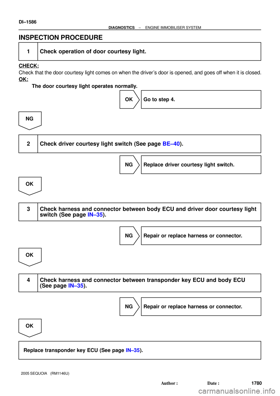
INSPECTION PROCEDURE
1 Check operation of door courtesy light.
CHECK:
Check that the door courtesy light comes on when the driver's door is opened, and goes off when it is closed.
OK:
The door courtesy light operates normally.
OK Go to step 4.
NG
2 Check driver courtesy light switch (See page BE±40).
NG Replace driver courtesy light switch.
OK
3 Check harness and connector between body ECU and driver door courtesy light
switch (See page IN±35).
NG Repair or replace harness or connector.
OK
4 Check harness and connector between transponder key ECU and body ECU
(See page IN±35).
NG Repair or replace harness or connector.
OK
Replace transponder key ECU (See page IN±35).
Page 1800 of 4323
I24836
ON
IND
(±) (+)
DI±1598
± DIAGNOSTICSENGINE IMMOBILISER SYSTEM
1792 Author�: Date�:
2005 SEQUOIA (RM1146U)
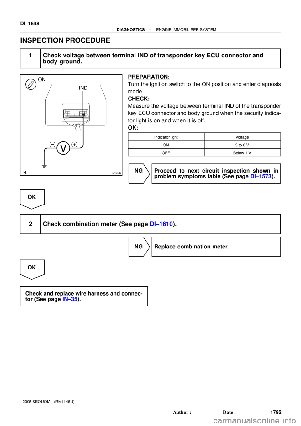
INSPECTION PROCEDURE
1 Check voltage between terminal IND of transponder key ECU connector and
body ground.
PREPARATION:
Turn the ignition switch to the ON position and enter diagnosis
mode.
CHECK:
Measure the voltage between terminal IND of the transponder
key ECU connector and body ground when the security indica-
tor light is on and when it is off.
OK:
Indicator lightVoltage
ON3 to 6 V
OFFBelow 1 V
NG Proceed to next circuit inspection shown in
problem symptoms table (See page DI±1573).
OK
2 Check combination meter (See page DI±1610).
NG Replace combination meter.
OK
Check and replace wire harness and connec-
tor (See page IN±35).
Page 1814 of 4323

DID8S±01
/ /
/ /
COMBINATION METER SYSTEM Check Sheet
Inspector 's name:
Customer 's NameVIN
Production Date
Licence Plate No.
Date Vehicle
Brought InOdometer Readingkm
miles
Weather Conditions
When Problem
OccurredFrequency Problem Occurs
Weather
Outside temperature� Constantly � Sometimes ( times per day, month)
� Once only Date Problem First Occurred
� Fine � Cloudy � Rainy � Snowy
� Various/Others
� Hot � Warm � Cool
� Cold (Approx. 5F ( 5C))
Problem Symptom
Gauge
� Malfunction in speedometer
� Malfunction in tachometer
� Malfunction in engine coolant temperature receiver gauge
� Malfunction in fuel receiver gauge
� Entire combination meter does not operate
� Buzzer does not sound (Key reminder warning, Seat belt warning)
� Seat belt warning for driver's seat does not operate
Others
� Operating light control rheostat does not change light brightness
�
�
�
�
�
�
�
�
� Malfunction in oil pressure receiver gauge
� Malfunction in volt meter DI±1612
± DIAGNOSTICSCOMBINATION METER SYSTEM
1806 Author�: Date�:
2005 SEQUOIA (RM1146U)
CUSTOMER PROBLEM ANALYSIS CHECK
Page 1816 of 4323

PROBLEM SYMPTOMS TABLE
HINT:
Inspect the related ºFuseº and ºRelayº before confirming the su")
DID8U±01
DI±1614
± DIAGNOSTICSCOMBINATION METER SYSTEM
1808 Author�: Date�:
2005 SEQUOIA (RM1146U)
PROBLEM SYMPTOMS TABLE
HINT:
Inspect the related ºFuseº and ºRelayº before confirming the suspected area as shown in the table below.
MALFUNCTION SYSTEM:
SymptomSuspected AreaSee page
Entire combination meter does not operate.Refer to troubleshooting proceduresDI±1628
Operating light control rheostat does not change light brightness.Refer to troubleshooting proceduresDI±1645
Seat belt warning does not operate.Refer to troubleshooting proceduresDI±1650
Key reminder warning buzzer does not sound.
1. Multiplex communication system
2. Key unlock warning switch circuit
3. Door courtesy lamp switch circuit
4. Combination meter assyDI±1892
DI±1715
DI±1728
IN±35
METER GAUGES:
SymptomSuspected AreaSee page
Malfunction in speedometerRefer to troubleshooting proceduresDI±1632
Malfunction in tachometerRefer to troubleshooting proceduresDI±1636
Malfunction in fuel receiver gaugeRefer to troubleshooting proceduresDI±1640
Malfunction in engine coolant temperature receiver gaugeRefer to troubleshooting proceduresDI±1644
Malfunction in oil pressure receiver gaugeRefer to troubleshooting proceduresDI±1654
Malfunction in volt meterRefer to troubleshooting proceduresDI±1658
WARNING LIGHTS:
SymptomSuspected AreaSee page
Check engine warning light (MIL) does not come on.
1. ECM
2. Wire harness or connector
3. Combination meter assyDI±9
±
IN±35
Discharge warning light does not come on.
1. ECM
2. Wire harness or connector
3. Combination meter assyDI±9
±
IN±35
Brake warning light does not come on.
1. Skid control ECU
2. Wire harness or connector
3. Combination meter assyDI±895
±
IN±35
ABS warning light does not come on.
1. Skid control ECU
2. Wire harness or connector
3. Combination meter assyDI±895
±
IN±35
SRS warning light does not come on.
1. Airbag sensor assy
2. Wire harness or connector
3. Combination meter assyDI±1126
±
IN±35
Open door warning light does not come on.
1. Door courtesy light switch circuit
2. Wire harness or connector
3. Combination meter assy
4. Body ECUDI±1728
±
IN±35
IN±35
Fuel level warning light does not come on.
1. Refer to troubleshooting
2. Wire harness or connector
3. Combination meter assyDI±1640
±
IN±35
Low oil pressure warning light does not come on.
1. Low oil pressure warning switch
2. Wire harness or connector
3. Combination meter assyBE±55
±
IN±35
Page 1819 of 4323

(c) Reconnect the C5 and C6 connectors.
(d) Measure the voltage of each terminal of the wire harness side")
± DIAGNOSTICSCOMBINATION METER SYSTEM
DI±1617
1811 Author�: Date�:
2005 SEQUOIA (RM1146U)
(c) Reconnect the C5 and C6 connectors.
(d) Measure the voltage of each terminal of the wire harness side connector.
Standard:
Terminals No.Wiring ColorTerminal DescriptionConditionSpecified Condition
C5±1 ± Body groundR±B ± Body
groundParking brake signalParking brake warning light ON6.7 to 12 V
C5±1 ± Body groundR±B ± Body
groundParking brake signalParking brake warning light OFFBelow 1 V
C5±2 ± Body groundLG±R ± Body
groundCRUISE signalCRUISE indicator light ONBelow 1 V
C5±2 ± Body groundLG±R ± Body
groundCRUISE signalCRUISE indicator light OFF10 to 14 V
C5±3 ± Body groundB ± Body groundIgnition switch signal
(Start)Ignition switch OFFBelow 1 V
C5±3 ± Body groundB ± Body groundIgnition switch signal
(Start)Ignition switch START10 to 14 V
C5±4 ± Body groundG±Y ± Body
groundSeat belt condition signal
(Driver side)D±BELT indicator light ONBelow 1 V
C5±4 ± Body groundG±Y ± Body
groundSeat belt condition signal
(Driver side)D±BELT indicator light OFF10 to 14 V
C5±13 ± Body groundLG±R ± Body
groundWasher level signalWASH LVL indicator light ONBelow 1 V
C5±13 ± Body groundLG±R ± Body
groundWasher level signalWASH LVL indicator light OFF10 to 14 V
C5±14 ± Body groundL±O ± Body
groundO/D OFF indicator signalO/D OFF indicator light ONBelow 1 V
C5±14 ± Body groundL±O ± Body
groundO/D OFF indicator signalO/D OFF indicator light OFF10 to 14 V
C5±15 (*1) ± Body groundY±R ± Body
groundA/T oil temperature signalA/T OIL TEMP. warning light ONBelow 1 V
C5±15 (*1) ± Body groundY±R ± Body
groundA/T oil temperature signalA/T OIL TEMP. warning light OFF10 to 14 V
C5±16 ± Body groundLG±B ± Body
groundSecurity indicator light
signal (Engine immobilizer
system)
Security indicator light ON10 to 14 V
C5±16 ± Body groundLG±B ± Body
groundSecurity indicator light
signal (Engine immobilizer
system)
Security indicator light OFFBelow 1 V
C5±17 ± Body groundGR ± Body
groundSecurity indicator light
signal (Theft deterrent
system)
Security indicator light ON10 to 14 V
C5±17 ± Body groundGR ± Body
groundSecurity indicator light
signal (Theft deterrent
system)
Security indicator light OFFBelow 1 V
C5±18 ± Body groundV±W ± Body
groundCHECK ENGINE signalCHECK ENGINE warning light ONBelow 1 V
C5±18 ± Body groundV±W ± Body
groundCHECK ENGINE signalCHECK ENGINE warning light OFF10 to 14 V
C5±19 ± Body groundG±B ± Body
groundA/T shift position signal
(L)A/T L indicator OFFBelow 1 V
Page 1964 of 4323
DI±1762
± DIAGNOSTICSBODY CONTROL SYSTEM
1956 Author�: Date�:
2005 SEQUOIA (RM1146U)
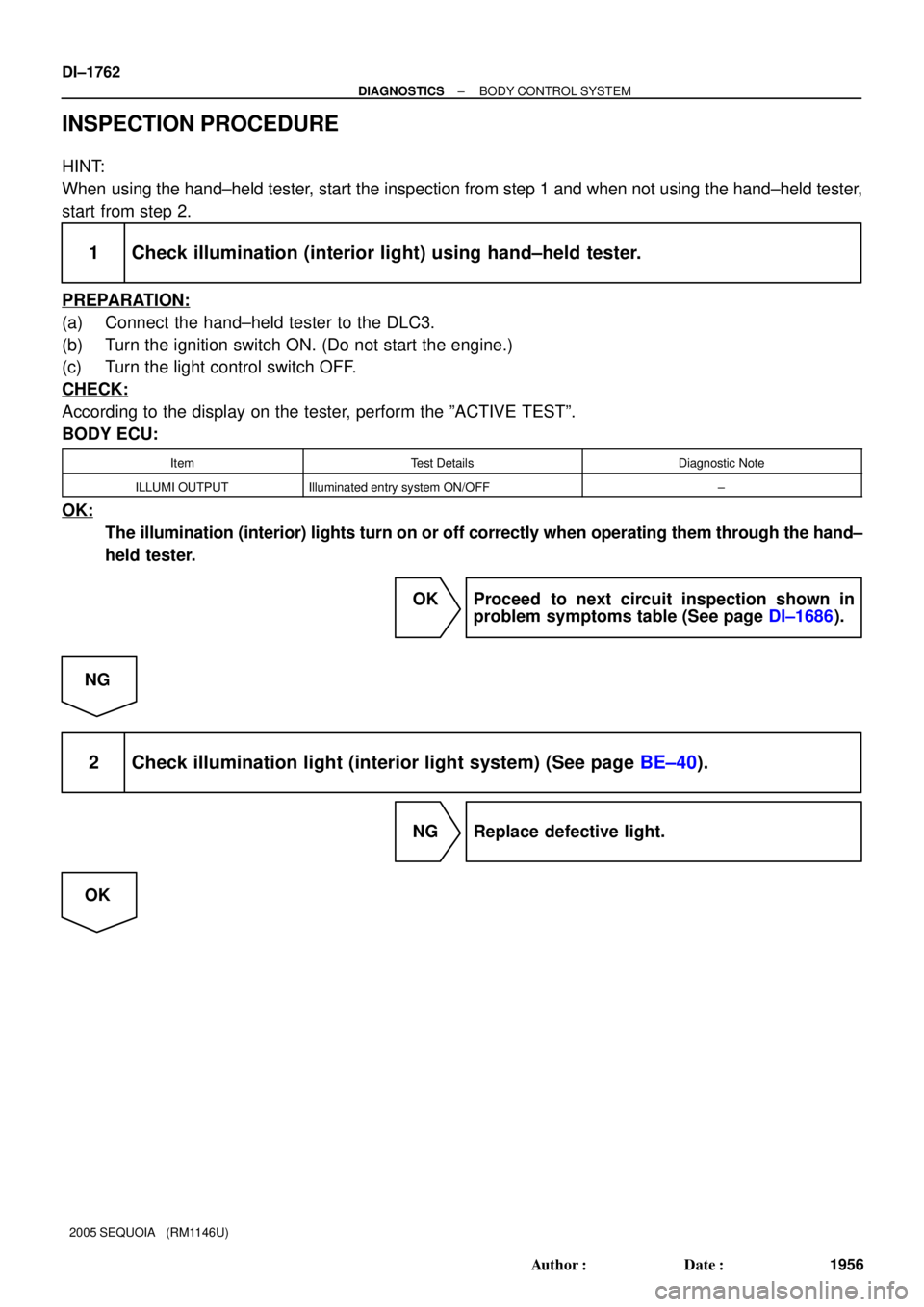
INSPECTION PROCEDURE
HINT:
When using the hand±held tester, start the inspection from step 1 and when not using the hand±held tester,
start from step 2.
1 Check illumination (interior light) using hand±held tester.
PREPARATION:
(a) Connect the hand±held tester to the DLC3.
(b) Turn the ignition switch ON. (Do not start the engine.)
(c) Turn the light control switch OFF.
CHECK:
According to the display on the tester, perform the ºACTIVE TESTº.
BODY ECU:
ItemTest DetailsDiagnostic Note
ILLUMI OUTPUTIlluminated entry system ON/OFF±
OK:
The illumination (interior) lights turn on or off correctly when operating them through the hand±
held tester.
OK Proceed to next circuit inspection shown in
problem symptoms table (See page DI±1686).
NG
2 Check illumination light (interior light system) (See page BE±40).
NG Replace defective light.
OK
Page 2168 of 4323

5. Identify the condition in which the noise occurs, and check the noise filter on the related part.
Condition in whic")
DI±1966
± DIAGNOSTICSAUDIO SYSTEM
2160 Author�: Date�:
2005 SEQUOIA (RM1146U)
5. Identify the condition in which the noise occurs, and check the noise filter on the related part.
Condition in which noise occursNoise Source
Depressing the acceleration pedal increases the noise, and stopping the
engine stops the noise immediately.Generator
Noise occurs during A/C or the heater operation.Blower motor
Rapid acceleration while driving on an unpaved road or after the ignition
switch is turned on makes noise.Fuel pump
Pressing and then releasing the horn switch, and keeping pressing the horn
switch makes unusual noise.Horn
Quiet noise is heard while the engine is running, but stops with the engine.Ignition
Noise occurs synchronously with the turn signal flash.Flasher
Noise occurs during window washer operation.Washer
Noise occurs while the engine is running, and it continues even after the en-
gine stops.Engine coolant temperature sensor
Noise occurs during wiper operation.Wiper
Noise occurs when the brake pedal is depressed.Stop light switch
Others.Static electricity stored on the vehicle
Reference:
�Make sure first that there is no noise from outside. Failing to do so makes the noise source detec-
tion difficult and leads to misdiagnosis.
�The noise should be removed in descending order of loudness.
�Tuning the radio so that no station is received wakes the noise more noticeable, making the rec-
ognition of the phenomenon easier.