Page 713 of 4323
B17411FC (+)E4
± DIAGNOSTICSENGINE
DI±511
705 Author�: Date�:
2005 SEQUOIA (RM1146U)
6 Check for open in harness and connector between circuit opening relay and fuel
pump, and fuel pump and body ground (See page IN±35).
NG Repair or replace harness or connector.
OK
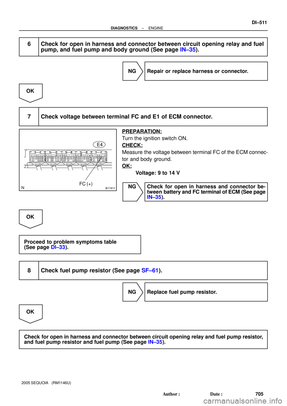
7 Check voltage between terminal FC and E1 of ECM connector.
PREPARATION:
Turn the ignition switch ON.
CHECK:
Measure the voltage between terminal FC of the ECM connec-
tor and body ground.
OK:
Voltage: 9 to 14 V
NG Check for open in harness and connector be-
tween battery and FC terminal of ECM (See page
IN±35).
OK
Proceed to problem symptoms table
(See page DI±33).
8 Check fuel pump resistor (See page SF±61).
NG Replace fuel pump resistor.
OK
Check for open in harness and connector between circuit opening relay and fuel pump resistor,
and fuel pump resistor and fuel pump (See page IN±35).
Page 715 of 4323
B17418W E5
± DIAGNOSTICSENGINE
DI±513
707 Author�: Date�:
2005 SEQUOIA (RM1146U)
INSPECTION PROCEDURE
HINT:
Troubleshoot each trouble symptom in accordance with the chart below.
MIL remains onStart inspection from step 1
MIL does not light upStart inspection from step 3
1 Clear DTC.
PREPARATION:
(a) Connect the hand±held tester to the DLC3.
(b) Turn the ignition switch ON and push the hand±held tester main switch ON.
(c) Read the DTC (See page DI±43).
(d) Clear the DTC (See page DI±43).
CHECK:
(a) Check that MIL does not light up.
OK:
Standard: MIL does not light up
OK Repair circuit indicated by output code
(See page DI±58).
NG
2 Check Harness and connector (Check for short in wire harness).
PREPARATION:
(a) Disconnect the E4 ECM connector.
(b) Turn the ignition switch ON.
CHECK:
(a) Check that MIL does not light up.
OK:
Standard: MIL does not light up
OK Replace ECM (See page SF±80).
NG
Check and repair harness and connector be-
tween combination meter and ECM.
Page 716 of 4323
DI±514
± DIAGNOSTICSENGINE
708 Author�: Date�:
2005 SEQUOIA (RM1146U)
3 Check that MIL lights up.
CHECK:
Check that MIL lights up when turning the ignition switch ON.
OK:
Standard: MIL lights up
OK System OK.
NG
4 Inspect combination meter assy (MIL circuit).
See the combination meter troubleshooting on page BE±55.
NG Repair or replace bulb or combination meter as-
sembly.
OK
Check and repair harness and connector be-
tween combination meter and ECM.
Page 726 of 4323

BASIC INSPECTION
1. CHECK FLUID LEVEL
(a) Using")
DIDIP±01
12345678
9 10111213141516
D13649
DLC3:
CG
TC
D13654
DI±524
± DIAGNOSTICSAUTOMATIC TRANSMISSION
718 Author�: Date�:
2005 SEQUOIA (RM1146U)
BASIC INSPECTION
1. CHECK FLUID LEVEL
(a) Using SST, create a short±circuit between terminals TC
and CG of the DLC3.
SST 09843±18040
(b) Start the engine and run at idle.
�The A/C switch must be turned off.
�On models with active height control suspension &
adaptive variable suspension, turn the height con-
trol switch off.
(c) Slowly move the shift lever through all positions from P to
L, and move it back to the P position.
(d) Switch to the fluid temperature detection mode.
Move the shift lever from the N to the D position, or from
D to N, within 1.5 seconds. (Repeat this operation for 6 se-
conds or more.)
OK: The A/T OIL TEMP warning light comes on for 2
seconds and then goes off.
(e) Return the shift lever to the P position and disconnect ter-
minals TC and CG.
(f) Idle the engine to raise oil temperature.
(g) Lift up the vehicle immediately after the meter indicator
light (ATF temperature warning light) comes on.
�The A/T OIL TEMP warning light indicates the ATF
temperature according to the following table.
ATF Temp.Less than optimized
temperatureOptimized temperatureMore than optimized
temperature
A/T OIL TEMP warning lightOFFONBlinking
Page 727 of 4323

(h) Remove the overflow plug and check the fluid le")
D14137
Refill Plug
Overflow Plug
D14142Control Shaft Lever
± DIAGNOSTICSAUTOMATIC TRANSMISSION
DI±525
719 Author�: Date�:
2005 SEQUOIA (RM1146U)
(h) Remove the overflow plug and check the fluid level.
Standard:
When ATF overflowsATF level is higher than specification
(Go to step (k))
When ATF does not overflow
ATF level is equal to or lower than
specification
(Go to step (i))
HINT:
�ºOverflowº indicates the condition under which ATF
drains out from the overflow tube.
�The capacity of the overflow tube is approximately 3 cc.
If the amount of drained ATF is little, only the fluid remain-
ing in the tube has drained out. This condition is not con-
sidered as ºoverflowº.
(i) Remove the refill plug.
(j) Add ATF through the refill hole until it flows out from the
overflow hole.
Fluid type: Toyota genuine ATF WS
(k) When the draining ATF has become a trickle, install the
overflow plug with a new gasket.
(l) Install the refill plug if removed.
(m) Lower the vehicle.
(n) Turn the ignition switch off to stop the engine.
2. CHECK FLUID CONDITION
If the fluid smells burnt or is black, replace it (see step 6).
3. INSPECT AND ADJUST SHIFT LEVER POSITION
(a) When shifting the shift lever from the N position to other
positions, check that the lever can be shifted smoothly
and accurately to each position and that the position indi-
cator comes on in accordance with the shift lever position.
If the indicator and shift lever position do not match, carry out
the following adjustment procedures.
(1) Remove the nut and disconnect the shift control
cable from the control shaft lever.
(2) Move the control shaft fully rearward.
(3) Return the control shaft lever 2 notches to the N
position.
(4) Set the shift lever to the N position.
(5) Connect the shift control cable and temporarily
install the control shaft lever nut.
(6) While holding the shift lever lightly toward the R
position side, tighten the control shaft lever nut.
Torque: 14.5 N´m (148 kgf´cm, 11 ft´lbf)
Page 728 of 4323
D07226
Neutral Basic Line
Bolt
Groove
DI±526
± DIAGNOSTICSAUTOMATIC TRANSMISSION
720 Author�: Date�:
2005 SEQUOIA (RM1146U)
(7) Start the engine and make sure that the vehicle
moves forward when shifting the lever from the N to
the D position and reverses when shifting it to the
R position.
4. INSPECT AND ADJUST PARK/NEUTRAL POSITION
(a) Check that the engine can be started when the shift lever
is in the N or P position, but cannot be started in other
positions.
If operation cannot be done as stated above, carry out the fol-
lowing adjustment procedures.
�Loosen the park/neutral position switch bolt and set
the shift lever to the N position.
�Align the groove with the neutral basic line.
�Hold in position and tighten the bolt.
Torque:13 N´m (130 kgf´cm, 9 ft´lbf)
(b) For continuity inspection of the park/neutral position
switch, see page DI±576.
5. CHECK IDLE SPEED
Idle speed (In N position and air conditioner OFF):
700 ± 50 rpm
Page 734 of 4323

(3) Install the overflow plug with a new gasket whe")
D14141
12345678
9 10111213141516
D13649
DLC3:
CG
TC
D13654
DI±532
± DIAGNOSTICSAUTOMATIC TRANSMISSION
726 Author�: Date�:
2005 SEQUOIA (RM1146U)
(3) Install the overflow plug with a new gasket when the
draining ATF has becomes a trickle.
Torque: 20 NVm (204 kgfVcm, 15 ftVlbf)
(4) Install the refill plug with a new O±ring.
Torque: 39 NVm (400 kgfVcm, 29 ftVlbf)
(5) Lower down the vehicle.
(6) Turn the ignition switch off.
(7) Check for fluid leaks in the transmission.
If there are leaks, it is necessary to repair or replace O±rings,
FIPGs, oil seals, plugs or other related parts.
(d) When adding a minimum amount of fluid: [*4]
(1) Using SST, create a short±circuit between terminals
TC and CG of the DLC3.
SST 09843±18040
(2) Start the engine and run at idle.
NOTICE:
The A/C switch must be turned off.
(3) Slowly move the shift lever from the P to the 2±L
position. Return the shift lever to the P position.
(4) Switch to the fluid temperature detection mode.
Move the shift lever from the N to the D position, or
from D to N, within 1.5 seconds. (Repeat this opera-
tion for 6 seconds or more.)
OK: The A/T OIL TEMP warning light comes on for 2
seconds and then goes off.
(5) Disconnect terminals TC and CG after confirming
the above condition.
(6) Idle the engine to raise the fluid temperature.
Page 735 of 4323

D14231
When fluid
temperature
is low: offWhen fluid
temperature
is correct: onWhen fluid
temperature
is high: blinks
D14139Overflow Plug
D14141
D14140
Refill Plug
± DIAGNOSTICSAUTOMATIC TRANSMISSION
DI±533
727 Author�: Date�:
2005 SEQUOIA (RM1146U)
(7) Lift up the vehicle immediately after the meter indi-
cator light (ATF temperature warning light) comes
on.
NOTICE:
�Add fluid only when the meter indicator light is on.
�Perform this procedure while the engine is idling.
(8) Remove the overflow plug. If ATF overflows, pro-
ceed to [*5]. If ATF does not overflow, proceed to
[*6].
HINT:
ºOverflowº indicates the condition under which ATF drains out
from the overflow tube.
(e) When fluid overflows: [*5]
(1) Install the overflow plug with a new gasket when the
draining ATF has become a trickle.
Torque: 20 NVm (204 kgfVcm, 15 ftVlbf)
(2) Install the refill plug with a new O±ring.
Torque: 39 NVm (400 kgfVcm, 29 ftVlbf)
(3) Lower down the vehicle.
(4) Turn the ignition switch off.
(5) Check for fluid leaks in the transmission.
If there are leaks, it is necessary to repair or replace O±rings,
FIPGs, oil seals, plugs or other related parts.
(f) When fluid does not overflow: [*6]
(1) Remove the refill plug.