Page 692 of 4323

(b) Monitor Conditions
(1) Allow the engine to idle for at least 5 minutes.
(2) Turn the ignition switch to OFF and wait for 6")
DI±490
± DIAGNOSTICSENGINE
684 Author�: Date�:
2005 SEQUOIA (RM1146U)
(b) Monitor Conditions
(1) Allow the engine to idle for at least 5 minutes.
(2) Turn the ignition switch to OFF and wait for 6 hours (8 or 10.5 hours).
HINT:
Do not start the engine until checking MONITOR STATUS. If the engine is started, the steps described above
must be repeated.
(c) Monitor Status
(1) Connect a hand±held tester to the DLC3.
(2) Turn the ignition switch to ON and turn the tester ON.
(3) On the tester, select the following menu items: DIAGNOSIS / ENHANCED OBD II / MONITOR
STATUS.
(4) Check the Monitor Status displayed on the tester.
HINT:
If INCMP is displayed, the monitor is not completed. Make sure that the preconditions have been met, and
perform the Monitor Conditions again.
2. PURGE FLOW MONITOR CONFIRMATION (P0441)
HINT:
Perform this monitor confirmation after the Key±Off Monitor Confirmation shows COMPL (complete).
(a) Preconditions
The monitor will not run unless:
�The vehicle has been driven for 10 minutes or more (in a city area or on a free way)
�The ECT is between 4.4�C and 35�C (40�F and 95�F)
�The IAT is between 4.4�C and 35�C (40�F and 95�F)
(b) Monitor Conditions
(1) Release the pressure from the fuel tank by removing and reinstalling the fuel tank cap.
(2) Warm the engine up until the ECT reaches more than 75�C (167�F).
(3) Increase the engine speed to 3,000 rpm once.
(4) Allow the engine to idle and turn A/C ON for 1 minute.
(c) Monitor Status
(1) Turn the ignition switch to OFF (where ON or the engine is running).
(2) Connect a hand±held tester to the DLC3.
(3) Turn the ignition switch to ON and turn the tester ON.
(4) On the tester, select the following menu items: DIAGNOSIS / ENHANCED OBD II / MONITOR
STATUS.
(5) Check the Monitor Status displayed on the tester.
HINT:
If INCMP is displayed, the monitor is not completed. Make sure that the preconditions have been met, and
perform the Monitor Conditions again.
Page 693 of 4323

MONITOR RESULT
Refer to page DI±26 for detailed information.
The test value and test limit information are described as shown")
± DIAGNOSTICSENGINE
DI±491
685 Author�: Date�:
2005 SEQUOIA (RM1146U)
MONITOR RESULT
Refer to page DI±26 for detailed information.
The test value and test limit information are described as shown in the following table. Check the monitor
result and test values after performing the monitor drive pattern (refer to ºConfirmation Monitorº).
�MID (Monitor Identification Data) is assigned to each emissions±related component.
�TID (Test Identification Data) is assigned to each test value.
�Scaling is used to calculate the test value indicated on generic OBD ll scan tools.
EVAP±Key±off monitor
MIDTIDScalingDescription of Test ValueMinimum Test LimitMaximum Test Limit
$3D$C9Multiply by 0.01
(kPa)Test value for small leak (P0456):
Refer to pressure D*.Minimum test limit for small
leakMaximum test limit for small
leak
$3D$CAMultiply by 0.01
(kPa)Test value for gross leak (P0455):
Refer to pressure E*.Minimum test limit for gross
leakMaximum test limit for gross
leak
$3D$CBMultiply by 0.01
(kPa)Test value for vacuum pump stuck OFF
(P2401):
Refer to pressure A*.Minimum test limit for vacuum
pump stuck OFFMaximum test limit for vacuum
pump stuck OFF
$3D$CDMultiply by 0.01
(kPa)Test value for vacuum pump stuck ON
(P2402):
Refer to pressure A*.Minimum test limit for vacuum
pump stuck ONMaximum test limit for vacuum
pump stuck ON
$3D$CEMultiply by 0.01
(kPa)Test value for vent valve stuck OFF
(vent) (P2420):
Refer to pressure C*.Minimum test limit for vent
valve stuck ONMaximum test limit for vent
valve stuck ON
$3D$CFMultiply by 0.01
(kPa)Test value for vent valve stuck ON
(closed) (P2419):
Refer to pressure A*.Minimum test limit for vent
valve stuck OFFMaximum test limit for vent
valve stuck OFF
$3D$D0Multiply by 0.01
(kPa)Test value for 0.02 inch orifice low flow
(P043E):
Refer to pressure B*.Minimum test limit for 0.02
inch orifice low flowMaximum test limit for 0.02
inch orifice low flow
$3D$D1Multiply by 0.01
(kPa)Test value for 0.02 inch orifice high flow
(P043F):
Refer to pressure A*.Minimum test limit for 0.02
inch orifice high flowMaximum test limit for 0.02
inch orifice high flow
$3D$D4Multiply by 0.01
(kPa)Test value for purge VSV stuck close
(P0441):
Refer to pressure F*.Minimum test limit for purge
VSV stuck closeMaximum test limit for purge
VSV stuck close
$3D$D5Multiply by 0.01
(kPa)Test value for purge VSV stuck open
(P0441):
Refer to pressure E*.Minimum test limit for purge
VSV stuck openMaximum test limit for purge
VSV stuck open
$3D$D7Multiply by 0.01
(kPa)Test value for purge flow (P0441):
Refer to pressure G*.Minimum test limit for purge
flowMaximum test limit for purge
flow
* Pressure A to G are indicated as shown in the diagram below.
Page 697 of 4323
B17411
+B E1(+)
(±)E6
E4
B17411
IGSW (+)E4
± DIAGNOSTICSENGINE
DI±495
689 Author�: Date�:
2005 SEQUOIA (RM1146U)
INSPECTION PROCEDURE
1 Check voltage between terminals +B and E1 of ECM connector.
PREPARATION:
Turn the ignition switch ON.
CHECK:
Measure the voltage between terminals +B and E1 of the ECM
connectors.
OK:
Standard: 9 to 14 V
OK Proceed to next circuit inspection shown in the
Problem symptoms table (See page BE±2).
NG
2 Check for open in harness and connector between terminal E1 of ECM and body
ground (See page IN±35).
NG Repair or replace harness or connector.
OK
3 Check voltage between terminal IGSW of ECM connector and body ground.
PREPARATION:
Turn the ignition switch ON.
CHECK:
Measure the voltage between terminal IGSW of the ECM con-
nector and body ground.
OK:
Standard: 9 to 14 V
OK Go to step 6.
NG
Page 698 of 4323
A21560
IGN1 Instrument
Panel J/B:
I08467
LOCKACC
ON
START
DI±496
± DIAGNOSTICSENGINE
690 Author�: Date�:
2005 SEQUOIA (RM1146U)
4 Check IGN1 fuse.
PREPARATION:
Remove the IGN1 fuse from the instrument panel J/B.
CHECK:
Check the resistance of the IGN1 fuse.
OK:
Below 1 W
NG Check for short in all harness and components
connected to IGN1 fuse.
OK
5 Check ignition switch (See page BE±24).
PREPARATION:
(a) Remove the lower finish panel.
(b) Disconnect the ignition switch connector.
CHECK:
Check resistance between terminals.
OK:
Standard:
Switch PositionTerminal ConditionSpecified Condition
LOCKAlways10 kW or more
ACC1 ± 3Below 1 W
ON1 ± 2 ± 3
5 ± 6Below 1 W
START1 ± 2
4 ± 5 ± 6Below 1 W
NG Replace ignition switch.
OK
Check and repair harness and connector be-
tween IGN fuse and ECM.
Page 699 of 4323
B17411MREL(+)E4
Engine Room
J/B:
A21381
EFI No. 1
Fuse
± DIAGNOSTICSENGINE
DI±497
691 Author�: Date�:
2005 SEQUOIA (RM1146U)
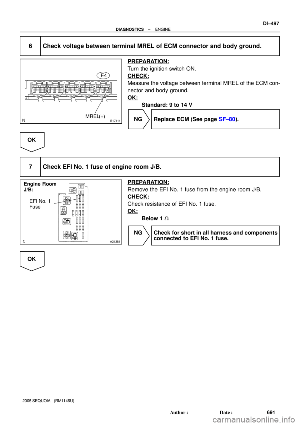
6 Check voltage between terminal MREL of ECM connector and body ground.
PREPARATION:
Turn the ignition switch ON.
CHECK:
Measure the voltage between terminal MREL of the ECM con-
nector and body ground.
OK:
Standard: 9 to 14 V
NG Replace ECM (See page SF±80).
OK
7 Check EFI No. 1 fuse of engine room J/B.
PREPARATION:
Remove the EFI No. 1 fuse from the engine room J/B.
CHECK:
Check resistance of EFI No. 1 fuse.
OK:
Below 1 W
NG Check for short in all harness and components
connected to EFI No. 1 fuse.
OK
Page 700 of 4323
A19288
EFI Relay
B17417
E4
MREL ECM Connector
DI±498
± DIAGNOSTICSENGINE
692 Author�: Date�:
2005 SEQUOIA (RM1146U)
8 Check EFI relay.
PREPARATION:
Remove the EFI relay from the engine room J/B.
CHECK:
Inspect the EFI relay.
OK:
Standard:
Terminal No.ConditionSpecified Condition
3 ± 5Always10 KW or higher
3 ± 5Apply B+ between
terminals 1 and 2Below 1 W
NG Replace EFI relay.
OK
9 Check for open and short in harness and connector between terminal MREL of
ECM and body ground.
PREPARATION:
Disconnect the E4 ECM connector.
CHECK:
Measure the resistance between the wire harness side connec-
tor and body ground.
OK:
Standard:
Tester ConnectionSpecified Condition
MREL (E4±8) ± Body groundBelow 1 W
NG Repair or replace harness or connector.
OK
Check for intermittent problems
(See page DI±11).
Page 703 of 4323
A00307
ON
VSV is ON VSV is OFF
Air Filter Air
Air
E
FE
F
BE6653
FI7073 FI7074
± DIAGNOSTICSENGINE
DI±501
695 Author�: Date�:
2005 SEQUOIA (RM1146U)
INSPECTION PROCEDURE
1 Connect hand±held tester, and check operation of VSV for ACIS.
PREPARATION:
(a) Connect the hand±held tester to the DLC3.
(b) Turn the ignition switch ON and push the hand±held tes-
ter main switch ON.
(c) Select the ACTIVE TEST mode on the hand±held tester.
CHECK:
Check the operation of the VSV when the VSV is operated by
the hand±held tester.
OK:
VSV is ON:
Air from port E flows out through port F.
VSV is OFF:
Air from port E flows out through the air filter.
OK Check for vacuum tank (See page SF±54).
NG
2 Check VSV for ACIS (See page SF±54).
NG Replace VSV for ACIS.
OK
Page 704 of 4323

3 Check for open and short in harness and connector be")
A23670
Wire Harness Side
V12
VSV for ACIS connector
B17413
E5E7
E1
ACIS
DI±502
± DIAGNOSTICSENGINE
696 Author�: Date�:
2005 SEQUOIA (RM1146U)
3 Check for open and short in harness and connector between EFI main relay
(Marking: EFI) and ECM (See page IN±35).
(a) Check the wire harness between the VSV for ACIS and
connector the ECM connector.
(1) Disconnect the VSV for ACIS connector.
(2) Disconnect the E5 and E7 ECM connector.
(3) Check for resistance between the wire harness side
connectors.
Standard (Check for open):
Symbols (Terminal No.)Specified condition
VSV for ACIS (V12±2) ± ACIS (E5±33)Below 1 W
Standard (Check for short):
Symbols (Terminal No.)Specified condition
VSV for ACIS (V12±2) or ACIS (E5±33) ± E1 (E7±1)10 kW or higher
(b) Check the wire harness between the VSV for ACIS con-
nector and the EFI relay.
(1) Disconnect the VSV for ACIS connector.
(2) Remove the EFI relay from the engine room R/B.
(3) Check for resistance between the wire harness side
connectors.
Standard (Check for open):
Symbols (Terminal No.)Specified condition
VSV for ACIS (V12±1) ± EFI relay terminal 3 of R/BBelow 1 W
NG Repair or replace harness or connector.
OK
Check and replace ECM (See page IN±35).