Page 2676 of 4323
A08928
ECM Connector ECM and Bracket AssemblyHeater to Register Dust
Lower No.2 Finish Panel
Glove Compartment Door
Wire Harness Connector (Cassette Connector)
A23366
Engine Wire Clamp
Engine WireHeater Hose Ground Strap
Fuel Inlet
HoseBattery
Negative
(±) Cable Heater Hose
Fuel Return
Hose
Generator Wire
Battery
Positive (+)
Terminal Clamp
Generator
Connector
EVAP Hose
w/o Hydraulic Brake Booster:
Brake Booster Tube
± ENGINE MECHANICALENGINE UNIT (4WD)
EM±89
2668 Author�: Date�:
2005 SEQUOIA (RM1146U)
Page 2680 of 4323

B07536
Disconnect
A08905
A08907
A08936
± ENGINE MECHANICALENGINE UNIT (4WD)
EM±93
2672 Author�: Date�:
2005 SEQUOIA (RM1146U)
(f) Disconnect the engine wire from the engine wire bracket
and remove the 2 nuts, bolt and bracket.
(g) Pull out the engine wire from the cowl panel.
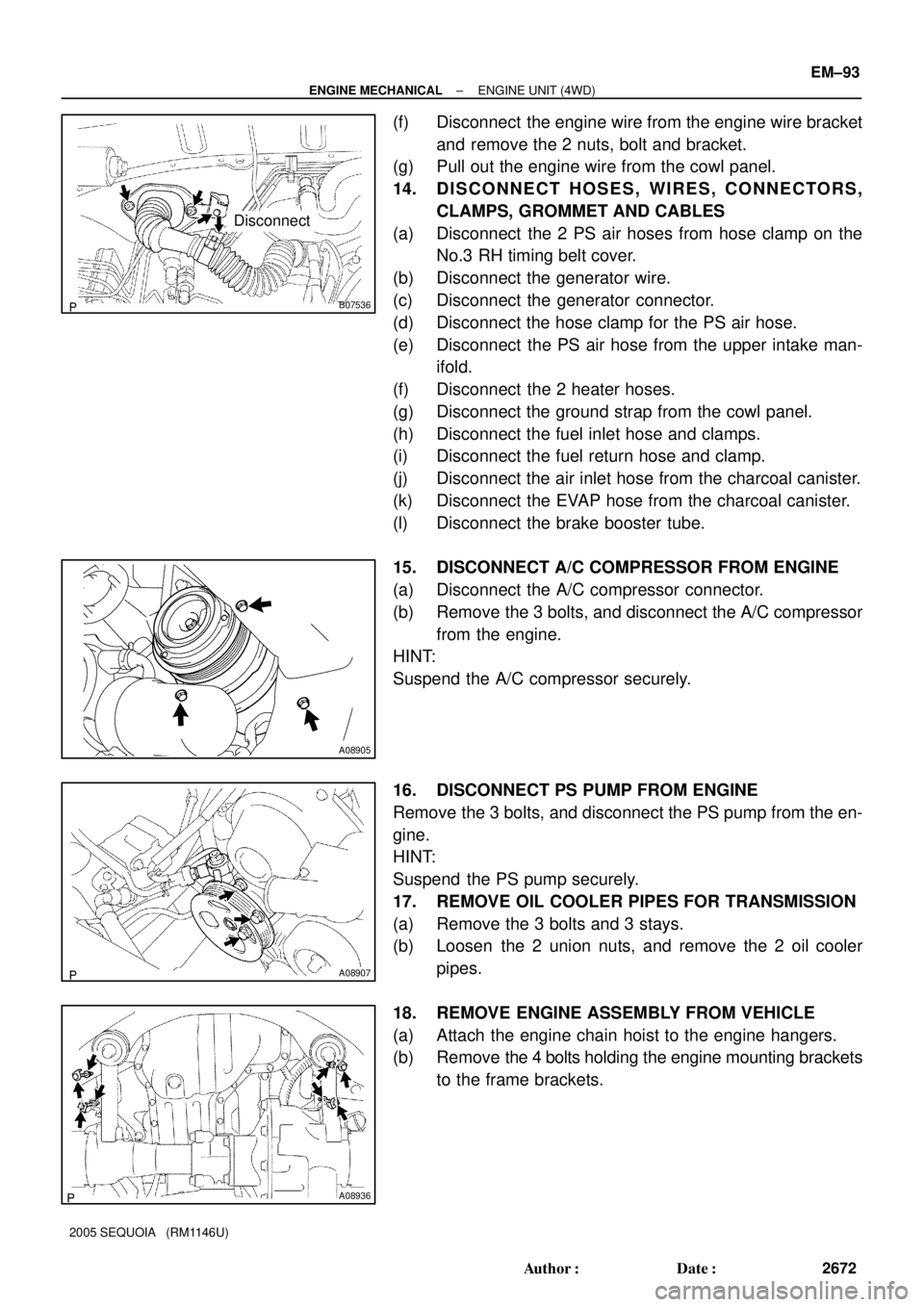
14. DISCONNECT HOSES, WIRES, CONNECTORS,
CLAMPS, GROMMET AND CABLES
(a) Disconnect the 2 PS air hoses from hose clamp on the
No.3 RH timing belt cover.
(b) Disconnect the generator wire.
(c) Disconnect the generator connector.
(d) Disconnect the hose clamp for the PS air hose.
(e) Disconnect the PS air hose from the upper intake man-
ifold.
(f) Disconnect the 2 heater hoses.
(g) Disconnect the ground strap from the cowl panel.
(h) Disconnect the fuel inlet hose and clamps.
(i) Disconnect the fuel return hose and clamp.
(j) Disconnect the air inlet hose from the charcoal canister.
(k) Disconnect the EVAP hose from the charcoal canister.
(l) Disconnect the brake booster tube.
15. DISCONNECT A/C COMPRESSOR FROM ENGINE
(a) Disconnect the A/C compressor connector.
(b) Remove the 3 bolts, and disconnect the A/C compressor
from the engine.
HINT:
Suspend the A/C compressor securely.
16. DISCONNECT PS PUMP FROM ENGINE
Remove the 3 bolts, and disconnect the PS pump from the en-
gine.
HINT:
Suspend the PS pump securely.
17. REMOVE OIL COOLER PIPES FOR TRANSMISSION
(a) Remove the 3 bolts and 3 stays.
(b) Loosen the 2 union nuts, and remove the 2 oil cooler
pipes.
18. REMOVE ENGINE ASSEMBLY FROM VEHICLE
(a) Attach the engine chain hoist to the engine hangers.
(b) Remove the 4 bolts holding the engine mounting brackets
to the frame brackets.
Page 2683 of 4323

A08936
A08907
A08905
EM±96
± ENGINE MECHANICALENGINE UNIT (4WD)
2675 Author�: Date�:
2005 SEQUOIA (RM1146U)
(d) Install the engine mounting brackets to the frame brack-
ets with the 2 nuts and 4 bolts.
Torque: 38 N´m (388 kgf´cm, 28 ft´lbf)
(e) Remove the engine chain hoist.
3. INSTALL PS PUMP
Install the PS pump with the 3 bolts.
Torque: 17 N´m (175 kgf´cm, 13 ft´lbf)
4. INSTALL A/C COMPRESSOR
(a) Install the A/C compressor with the 3 bolts.
Torque: 49 N´m (500 kgf´cm, 36 ft´lbf)
(b) Connect the A/C compressor connector.
5. CONNECT HOSES, WIRES, CONNECTORS, CLAMPS,
GROMMET AND CABLES
(a) Connect the 2 PS air hoses to hose clamp on the No.3 RH
timing belt cover.
(b) Connect the generator wire.
(c) Connect the generator connector.
(d) Connect the hose clamp for the PS air hose.
(e) Connect the PS air hose to the upper intake manifold.
(f) Connect the 2 heater hoses.
(g) Connect the ground strap to the cowl panel.
(h) Connect the fuel inlet hose and clamps.
(i) Connect the fuel return hose and clamp.
(j) Connect the air inlet hose to the charcoal canister.
(k) Connect the EVAP hose to the charcoal canister.
(l) Connect the brake booster tube.
6. CONNECT ENGINE WIRE TO CABIN
(a) Push into the engine wire through the cowl panel.
Page 2717 of 4323
EC087±03
± EMISSION CONTROLEMISSION CONTROL SYSTEM
EC±1
2709 Author�: Date�:
2005 SEQUOIA (RM1146U)
EMISSION CONTROL SYSTEM
PURPOSE
The emission control systems are installed to reduce the amount of HC, CO and NOx exhausted from the
engine ((3) and (4)), to prevent the atmospheric release of blow±by gas±containing HC (1) and evaporated
fuel containing HC being released from the fuel tank (2).
The function of each system is shown in these table:
SystemAbbreviationFunction
(1) Positive Crankcase Ventilation
(2) Evaporative Emission Control
(3) Three±Way Catalytic Converter
(4) Sequential Multiport Fuel Injection*PCV
EVAP
TWC
SFIReduces HC
Reduces evaporated HC
Reduces HC, CO and NOx
Injects a precisely timed, optimum amount of fuel for reduced exhaust
emissions
Remark: * For inspection and repair of the SFI system, refer to the SF section in this manual.
Page 2720 of 4323
EC089±06
B17455
Charcoal
Canister
VSV for EVAP
Air Injection
Control DriverTWC EVAP
Service
PortPurge Line VENT Line
ECM Fuel Tank
Air Filter
ECM To Intake Manifold
Pump Module
M
P
Pressure
Sensor Pump MotorVent ValveRefueling Valve
Air Inlet Line
MP
Air Switching
Valve
Air Switching
Valve No.2
VSVs Air PumpPressure
Sensor
EVAPORATIVE EMISSION (EVAP) CONTROL SYSTEM
SECONDARY AIR INJECTION SYSTEM EC±4
± EMISSION CONTROLPARTS LAYOUT AND SCHEMATIC DRAWING
2712 Author�: Date�:
2005 SEQUOIA (RM1146U)
DRAWING
Page 2725 of 4323

EC0JL±03
B17594
Gasket
B06544
Vacuum Gauge
D13872
Hand±Held Tester
DLC3
CAN VIM
± EMISSION CONTROLEVAPORATIVE EMISSION (EVAP) CONTROL SYSTEM
EC±9
2717 Author�: Date�:
2005 SEQUOIA (RM1146U)
INSPECTION
1. INSPECT LINES AND CONNECTIONS
Visually check for loose connections, sharp bends or damage.
2. INSPECT FUEL TANK
Visually check for deformation, cracks or fuel leakage.
3. INSPECT FUEL TANK CAP
Visually check if the cap and/or gasket are deformed or dam-
aged.
If necessary, repair or replace the cap.
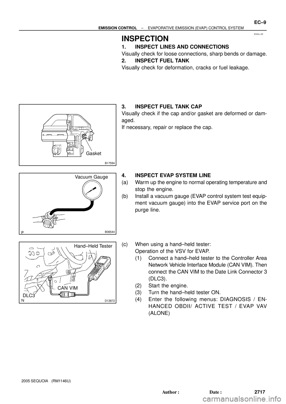
4. INSPECT EVAP SYSTEM LINE
(a) Warm up the engine to normal operating temperature and
stop the engine.
(b) Install a vacuum gauge (EVAP control system test equip-
ment vacuum gauge) into the EVAP service port on the
purge line.
(c) When using a hand±held tester:
Operation of the VSV for EVAP.
(1) Connect a hand±held tester to the Controller Area
Network Vehicle Interface Module (CAN VIM). Then
connect the CAN VIM to the Date Link Connector 3
(DLC3).
(2) Start the engine.
(3) Turn the hand±held tester ON.
(4) Enter the following menus: DIAGNOSIS / EN-
HANCED OBDII/ ACTIVE TEST / EVAP VAV
(ALONE)
Page 2727 of 4323

B06546
Pressure Gauge
Pressure
B17596
Fuel Tank Cap
Pressure
Gauge
B17662
Fuel Tank CapFuel Tank
Vent Line Hose
± EMISSION CONTROLEVAPORATIVE EMISSION (EVAP) CONTROL SYSTEM
EC±11
2719 Author�: Date�:
2005 SEQUOIA (RM1146U)
(4) Apply pressure (13.5 to 15.5 in.Aq, 0.99 to 1.14
in.Hq) from the EVAP service port.
Pressure:
The gauge should still read over 7.7 to 8.8 in.Aq (0.57
to 0.65 in.Hq) for 2 minutes after the pressure is ap-
plied.
HINT:
If you cannot apply pressure, the hose connecting the VSV,
charcoal canister and fuel tank has slipped off or the VSV is
open.
(5) Check if the pressure decreases when the fuel tank
cap is removed while applying pressure.
HINT:
If the pressure does not decrease when the filler cap is re-
moved, the hose connecting the service port and the fuel tank
may be blocked.
(k) Disconnect the pressure gauge from the EVAP service
port on the purge line.
5. INSPECT FUEL CUTOFF VALVE AND FILL CHECK
VA LV E
(a) Disconnect the vent line hose from the fuel tank.
(b) Connect the pressure gauge to the fuel tank.
(c) Fill the fuel tank with fuel.
(d) Apply pressure of 4 kPa (41 gf/cm
2,0.58 psi) to the vent
port of the fuel tank.
HINT:
It is necessary to check the amount of fuel in the fuel tank. When
the fuel tank is full, the float valve of the fill check valve is closed
and no air can pass through.
(e) Remove the fuel tank cap, and check that the pressure
drops.
If the pressure does not drop, replace the fuel tank assembly.
(f) Reconnect the vent line hose to the fuel tank.
Page 2736 of 4323
B17518
� Gasket
� Gasket Air Switching Valve No.2
Air Tube No.3
Air Tube No.3� GasketInjection Connector Engine Wire
VSV Connector
for EVAP Fuel Return Hose
N´m (kgf´cm, ft´lbf): Specified torque
� Non±reusable part
� Gasket
� Gasket
Air Pump Assembly
Intake Manifold Assembly
� Gasket
� Gasket
7.5 (76, 66 in.´lbf)
VSV for Air Injection System
18 (185, 13)
18 (185, 13)
18 (185, 13)
10 (102, 7 )
16 (163, 12)
16 (163, 12)
10 (102, 7 )
10 (102, 7)
EC±20
± EMISSION CONTROLSECONDARY AIR INJECTION SYSTEM
2728 Author�: Date�:
2005 SEQUOIA (RM1146U)