Page 1254 of 4323
F19781
Translate ECU
O
J43
J/C
O A
A 8
5
BF10
Fusible
Link
Block ALTW±B 40
T5 GND
A
A J18
J/CW±B
W±B W±B
IL11
S1
32
S1 9
IL1GND1
GND2
Battery
IGIGABS & VSC Actuator
(Skid Control ECU)
VSC+
VSC±
IG1CANH
CANL
BZ
17 L
T5
11
T5
1
T56
S1
2
S1
22
S1 IL27
IL26
IL1 15 WL
W
B±R B±R
B±RW±L
W±L
B±R
B±R
W W±LB±Y
WV5
VSC Warning Buzzer
Buzzer J37A
J38A
J37A
3C8
3A8
1F4
1L1 1C4
6
1C I18
Ignition SW
12
AM1
IG1
AM1 ECU±IG Sub J/B No.3
Instrument Panel J/B21
1 2
O 7
J/C (*) CAN1 Circuit
(*)
(*)(*)
(*) DI±1052
± DIAGNOSTICSABS WITH EBD & BA & TRAC & VSC SYSTEM
1246 Author�: Date�:
2005 SEQUOIA (RM1146U)
VSC Buzzer Circuit
CIRCUIT DESCRIPTION
The VSC buzzer sounds during VSC operation.
WIRING DIAGRAM
DI949±03
Page 1255 of 4323

INSPECTION PROCEDURE
HINT:
Start the inspection from step 1 when using the hand±held tester")
± DIAGNOSTICSABS WITH EBD & BA & TRAC & VSC SYSTEM
DI±1053
1247 Author�: Date�:
2005 SEQUOIA (RM1146U)
INSPECTION PROCEDURE
HINT:
Start the inspection from step 1 when using the hand±held tester and start from step 2 when not using the
hand±held tester.
1 Check operation of the VSC buzzer.
PREPARATION:
(a) Connect the hand±held tester to the DLC3.
(b) Turn the ignition switch to the ON position and push the hand±held tester main switch ON.
(c) Select ACTIVE TEST mode on the hand±held tester.
CHECK:
Check ºON±OFFº function of the VSC buzzer with the hand±held tester.
ItemVehicle Condition / Test DetailsDiagnostic Note
VSC / BR WARN BUZTurns VSC / BRAKE warning buzzer ON / OFFBuzzer can be heard
OK:
Buzzer sound can be heard.
OK Replace skid control ECU
(See page BR±52).
NOTICE:
When replacing the skid control ECU, perform the zero
point calibration (See page DI±897).
NG
2 Check voltage between terminal 2 of the VSC buzzer and body ground.
PREPARATION:
Remove the VSC buzzer with connectors still connected.
CHECK:
(a) Turn the ignition switch to the ON position.
(b) Measure the voltage between terminal (2) of the VSC buzzer and body ground.
OK:
Voltage: 10 to 14 V
NG Repair or replace harness or connector from
voltage supply to VSC buzzer.
OK
Page 1257 of 4323
F19788
6
IL2
7 CANL
S12
VSC+ 6
TC 28Translate ECU
CANH11
VSC±
TC
CG
J43
J/CIG 4A55
4BP±B W
L ABS & VSC Actuator
(Skid Control ECU)
7
S1T5
T5
T5 W
L
IL2
P±B D6
Data Link Connector 3
O 13
4Sub J/B No. 4
O
AA (*) CAN1 Circuit
(*)
(*)
(*) (*)
± DIAGNOSTICSABS WITH EBD & BA & TRAC & VSC SYSTEM
DI±1055
1249 Author�: Date�:
2005 SEQUOIA (RM1146U)
Tc Terminal Circuit
CIRCUIT DESCRIPTION
Connecting terminals Tc and CG of the DLC3 causes the skid control ECU to indicate the DTC by blinking
the ABS warning light, VSC TRAC warning light and BRAKE warning light.
WIRING DIAGRAM
DI94B±04
Page 1258 of 4323
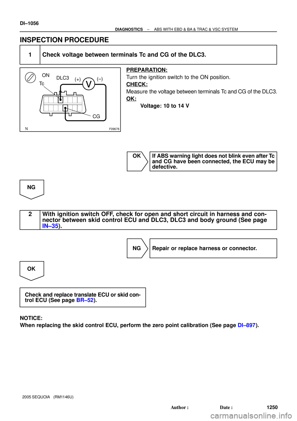
F09678
ON
DLC3
Tc
CG (+)(±)
DI±1056
± DIAGNOSTICSABS WITH EBD & BA & TRAC & VSC SYSTEM
1250 Author�: Date�:
2005 SEQUOIA (RM1146U)
INSPECTION PROCEDURE
1 Check voltage between terminals Tc and CG of the DLC3.
PREPARATION:
Turn the ignition switch to the ON position.
CHECK:
Measure the voltage between terminals Tc and CG of the DLC3.
OK:
Voltage: 10 to 14 V
OK If ABS warning light does not blink even after Tc
and CG have been connected, the ECU may be
defective.
NG
2 With ignition switch OFF, check for open and short circuit in harness and con-
nector between skid control ECU and DLC3, DLC3 and body ground (See page
IN±35).
NG Repair or replace harness or connector.
OK
Check and replace translate ECU or skid con-
trol ECU (See page BR±52).
NOTICE:
When replacing the skid control ECU, perform the zero point calibration (See page DI±897).
Page 1260 of 4323
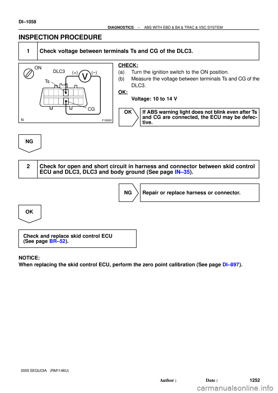
F18920
DLC3
Ts
CG ON
(+) (±)
DI±1058
± DIAGNOSTICSABS WITH EBD & BA & TRAC & VSC SYSTEM
1252 Author�: Date�:
2005 SEQUOIA (RM1146U)
INSPECTION PROCEDURE
1 Check voltage between terminals Ts and CG of the DLC3.
CHECK:
(a) Turn the ignition switch to the ON position.
(b) Measure the voltage between terminals Ts and CG of the
DLC3.
OK:
Voltage: 10 to 14 V
OK If ABS warning light does not blink even after Ts
and CG are connected, the ECU may be defec-
tive.
NG
2 Check for open and short circuit in harness and connector between skid control
ECU and DLC3, DLC3 and body ground (See page IN±35).
NG Repair or replace harness or connector.
OK
Check and replace skid control ECU
(See page BR±52).
NOTICE:
When replacing the skid control ECU, perform the zero point calibration (See page DI±897).
Page 1265 of 4323
DIDHZ±01
F19815
: CAN Main Bus Line
(CAN±H) DLC3
120 W
± 10%
Suspension
Control ECU ECM
: CAN Main Bus Line
(CAN±L)
: CAN Sub Bus Line
(CAN±H) : CAN Sub Bus Line
(CAN±L)120 W
± 10% Serial Communication Line
Translate ECU
*1: w/ Air Suspension System*1 *1Junction
Connector
± DIAGNOSTICSCAN COMMUNICATION SYSTEM
DI±1063
1257 Author�: Date�:
2005 SEQUOIA (RM1146U)
SYSTEM DIAGRAM
HINT:
�The ECM uses the CAN communication system to perform DTC communication instead of the conven-
tional serial communication line (SIL).
�The translate ECU outputs DTCs only via the BRAKE warning light. Therefore, the DTCs cannot be
checked on the hand±held tester display via the CAN VIM.
Page 1276 of 4323
![TOYOTA SEQUOIA 2001 Service Repair Manual DIDI6±01
Action when unable to communicateDTC detection
(Driver detectable)
Suspension
Control ECUVSC/TRC function stops
[When unable to communicate with ECM]
Function stops (Vehicle height cannot b](/manual-img/14/57465/w960_57465-1275.png "TOYOTA SEQUOIA 2001 Service Repair Manual DIDI6±01
Action when unable to communicateDTC detection
(Driver detectable)
Suspension
Control ECUVSC/TRC function stops
[When unable to communicate with ECM]
Function stops (Vehicle height cannot b")
DIDI6±01
Action when unable to communicateDTC detection
(Driver detectable)
Suspension
Control ECUVSC/TRC function stops
[When unable to communicate with ECM]
Function stops (Vehicle height cannot be changed until the ignition
switch is turned off)
[When unable to communicate with Translate ECU]
Vehicle height is maintained at the normal level until the ignition
switch is turned off. If communication is still impossible even after
the ignition switch is turned on again, the same height is maintained.Not detectable
( )
Not detectable
(VSC warning lamp
comes on)
Detectable
(Only DTCs are stored) ECMTranslate ECU
Suspension Control ECU
Rx
TxTx
Rx
Tx TxTx
Rx
ECM
Translate ECU DI±1074
± DIAGNOSTICSCAN COMMUNICATION SYSTEM
1268 Author�: Date�:
2005 SEQUOIA (RM1146U)
FAIL±SAFE CHART
1. FAIL±SAFE FUNCTION
(a) When communication fails in any of the CAN bus lines (communication lines) due to a short circuit or
any other cause, the fail±safe function, which is specified for each system, operates to prevent the
system from malfunctioning.
(b) Effects on each system when communication is impossible are as follows.
HINT:
�Rx: Reception from each ECU.
�Tx: Transmission to each ECU.
Page 1277 of 4323

DIAGNOSTIC TROUBLE CODE CHART
1. DTC TABLE BY ECU
HINT:
�If CAN communication system DTCs are ou")
DIDI7±01
± DIAGNOSTICSCAN COMMUNICATION SYSTEM
DI±1075
1269 Author�: Date�:
2005 SEQUOIA (RM1146U)
DIAGNOSTIC TROUBLE CODE CHART
1. DTC TABLE BY ECU
HINT:
�If CAN communication system DTCs are output, trouble cannot be determined only by the DTCs. Per-
form troubleshooting according to ºHOW TO PROCEED WITH TROUBLESHOOTINGº (see page
DI±1065).
(a) Skid Control ECU
HINT:
�DTC communication uses the SIL line.
�If C1201/51, C1202/52 or C1203/53 is output from skid control ECU, perform troubleshooting of each
diagnosis code (see page DI±921).
DTC No.Detection Item
U0100/65Lost Communication With ECM/PCM ºAº
(b) ECM
HINT:
The ECM is connected to the CAN communication system, but CAN communication system DTCs are not
output.
(c) Translate ECU
HINT:
The translate ECU outputs DTCs only via the BRAKE warning light. Therefore, the DTCs cannot be checked
on the hand±held tester display via the CAN VIM.
DTC No.Detection Item
65Abnormalities in EFI communication
94Abnormalities in CAN communication
(d) Suspension Control ECU
HINT:
DTC communication uses the SIL line.
DTC No.Detection Item
U0100/65Lost Communication With ECM/PCM ºAº
U0122/67Lost Communication With Vehicle Dynamics Control Module
U0132/74Lost Communication With Ride Level Control Module

VSC+
VSC")

7
S1T5
T5
T5 W
L
IL2
P±B D6
Data Link Connector 3
O 13
4Sub J/B No")
 DLC3
120 W
± 10%
Suspension
Control ECU ECM
: CAN Main Bus Line
(CAN±L)
: CAN Sub Bus Line
(CAN±H) : CAN Sub Bus Line
(CAN±L)120 W
± 10% Seri")