Page 3247 of 4323
SR1F3±03
F17895
Steering Wheel Pad
Steering
Wheel
Column Lower
CoverCombination
SwitchSteering Column Assembly
Transmission Control
Cable Assembly
Lower LH Finish PanelColumn Hole
Cover No. 2
No. 2 Universal
Joint Assembly
No. 2 Heater to Register Dust Torx® Screw
35 (360, 26)
35 (360, 26)
8.0 (82, 71 in.´lbf)
26 (260, 19)
26 (260, 19)
8.8 (90, 78 in.´lbf)
50 (510, 37)
8.8 (90, 78 in.´lbf)
Front Door Scuff PlateCowl Side Trim
Hood Lock
Release Lever
8.0 (82, 71 in.´lbf)
Side Panel
No. 2 Intermediate
Shaft AssemblyBrake Pedal
Return Spring
Column Upper Cover
N´m (kgf´cm, ft´lbf): Specified torque
Steering Wheel Lower
No. 3 Cover
Steering Wheel Lower
No. 2 Cover
35 (360, 26)
Sliding Yoke
Torx® Screw SR±12
± STEERINGTILT STEERING COLUMN
3239 Author�: Date�:
2005 SEQUOIA (RM1146U)
TILT STEERING COLUMN
COMPONENTS
Page 3249 of 4323

REMOVAL
1. DIS")
SR1KD±01
F17124
Screw CaseTorx® Screw
F17904
Correct
Wrong
Airbag Connectors
F06699
Matchmarks
SST
SR±14
± STEERINGTILT STEERING COLUMN
3241 Author�: Date�:
2005 SEQUOIA (RM1146U)
REMOVAL
1. DISCONNECT CABLE FROM NEGATIVE BATTERY
TERMINAL
Wait for 90 seconds after disconnecting the cable to prevent the
airbag working.
2. REMOVE STEERING WHEEL PAD
NOTICE:
If the airbag connector is disconnected with the ignition
switch in the ACC or ON position, DTCs will be recorded.
(a) Place the front wheels facing straight ahead.
(b) Remove the steering wheel lower No. 3 cover.
(c) Remove the steering wheel lower No. 2 cover.
(d) Using a torx® socket wrench (T30), loosen the 2 torx®
screws.
HINT:
Loosen each screw until the groove along the screw circumfer-
ence is caught on the screw case.
(e) Pull out the wheel pad from the steering wheel.
(f) Using a screwdriver, disconnect the airbag connectors.
CAUTION:
�When storing the steering wheel pad, keep the upper
surface of the pad facing upward.
�Never disassemble the steering wheel pad.
NOTICE:
When removing the steering wheel pad, take care not to
pull the airbag wire harness.
(g) Disconnect the horn terminal and remove the steering
wheel pad.
3. REMOVE STEERING WHEEL
(a) Remove the steering wheel set nut.
(b) Put matchmarks on the steering wheel and main shaft as-
sembly.
(c) Using SST, remove the wheel.
SST 09950±50013 (09951±05010, 09952±05010,
09953±05020, 09954±05021)
4. REMOVE UPPER AND LOWER COLUMN COVERS
Remove the 3 screws, upper and lower column covers.
Page 3259 of 4323

5. INSTALL COLUMN HOLE COVER NO. 2
Install the column hole cover No. 2 to t")
F13260
F17896
BMatchmarks
A
F19948
Mark
SR±24
± STEERINGTILT STEERING COLUMN
3251 Author�: Date�:
2005 SEQUOIA (RM1146U)
5. INSTALL COLUMN HOLE COVER NO. 2
Install the column hole cover No. 2 to the body with the 3 bolts.
Torque: 8.0 N´m (82 kgf´cm, 71 in.´lbf)
6. INSTALL SLIDING YOKE
(a) Align the matchmark on the sliding yoke with the one on
the No. 2 intermediate shaft assembly.
(b) Install the ºBº bolt.
Torque: 35 N´m (360 kgf´cm, 26 ft´lbf)
(c) Install the ºAº bolt.
Torque: 35 N´m (360 kgf´cm, 26 ft´lbf)
7. INSTALL BRAKE PEDAL RETURN SPRING
8. INSTALL NO. 2 HEATER TO REGISTER DUCT
9. INSTALL LOWER LH FINISH PANEL
(a) Install the lower LH finish panel with the 4 bolts.
(b) Connect the hood lock release lever with the 2 screws.
10. INSTALL COWL SIDE TRIM AND FRONT DOOR
SCUFF PLATE
11. INSTALL SPIRAL CABLE (See page BE±26)
12. INSTALL COMBINATION SWITCH WITH SPIRAL
CABLE
(a) Install the combination switch with the 3 screws.
(b) Connect the airbag connector.
(c) Connect the 4 connectors.
13. INSTALL UPPER AND LOWER COLUMN COVERS
Install the upper and lower column covers with the 3 screws.
14. CENTER SPIRAL CABLE
(a) Check that the front wheels are facing straight ahead.
(b) Turn the cable counterclockwise by hand until it feels firm.
(c) Then rotate the cable clockwise about 2.5 turns to align
the marks.
HINT:
The cable will rotate about 2.5 turns to both the left and right
from the center.
Page 3260 of 4323

15. INSTALL STEERING WHEEL
(a) Align the matchmark on the wheel with the one on the")
F17129
Torx® Screw
Screw Case
± STEERINGTILT STEERING COLUMN
SR±25
3252 Author�: Date�:
2005 SEQUOIA (RM1146U)
15. INSTALL STEERING WHEEL
(a) Align the matchmark on the wheel with the one on the
main shaft.
(b) Install the wheel set nut.
Torque: 50 N´m (510 kgf´cm, 37 ft´lbf)
16. INSTALL STEERING WHEEL PAD
NOTICE:
�Never use airbag parts from another vehicle. When
replacing parts, replace with new ones.
�Make sure that the wheel pad is installed with the spe-
cified torque.
�If the wheel pad has been dropped, or there are
cracks, dents or other defects on the case or connec-
tor, replace the wheel pad with a new one.
�When installing the wheel pad, take care that the wir-
ings do not interfere with other parts and are not
pinched between other parts.
(a) Connect the horn terminal.
(b) Connect the airbag connectors.
(c) Install the wheel pad after confirming that the circumfer-
ence groove of the torx® screw is caught on the screw
case.
(d) Using a torx® socket wrench (T30), tighten the 2 torx®
screws.
Torque: 8.8 N´m (90 kgf´cm, 78 in.´lbf)
(e) Install the steering wheel lower No. 2 cover.
(f) Install the steering wheel lower No. 3 cover.
17. CHECK STEERING WHEEL CENTER POINT
18. CONNECT CABLE TO NEGATIVE BATTERY TERMI-
NAL
19. PERFORM INITIALIZATION (See page IN±20)
Some systems need initialization when disconnecting the cable
from the negative battery terminal.
Page 3275 of 4323
SR02O±09
F13616SST
SR±40
± STEERINGPOWER STEERING GEAR
3267 Author�: Date�:
2005 SEQUOIA (RM1146U)
REMOVAL
NOTICE:
Remove the steering wheel assembly before the steering
gear removal, because there is possibility of breaking of
the spiral cable.
1. DISCONNECT CABLE FROM NEGATIVE BATTERY
TERMINAL
Wait for 90 seconds after disconnecting the cable to prevent the
airbag working.
2. PLACE FRONT WHEELS FACING STRAIGHT AHEAD
3. REMOVE STEERING WHEEL PAD
(See page SR±14)
4. REMOVE STEERING WHEEL (See page SR±14)
5. DISCONNECT RH AND LH TIE ROD ENDS
(See page SA±86)
6. DISCONNECT NO. 2 INTERMEDIATE SHAFT AS-
SEMBLY (See page SR±14)
7. DISCONNECT CLAMP PLATE
Remove the bolt and disconnect the clamp plate.
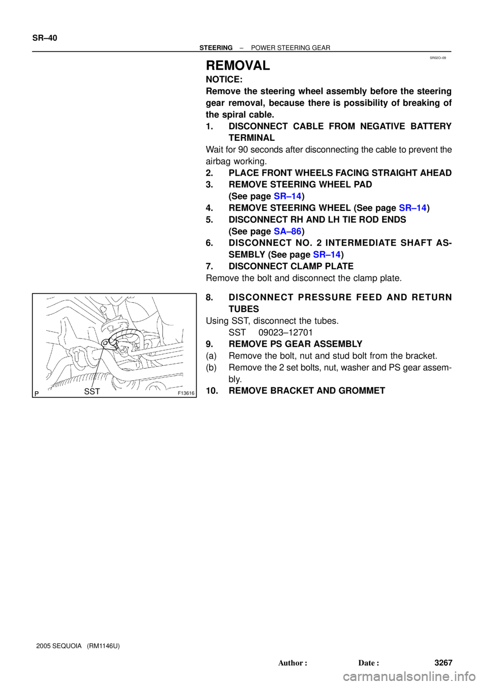
8. DISCONNECT PRESSURE FEED AND RETURN
TUBES
Using SST, disconnect the tubes.
SST 09023±12701
9. REMOVE PS GEAR ASSEMBLY
(a) Remove the bolt, nut and stud bolt from the bracket.
(b) Remove the 2 set bolts, nut, washer and PS gear assem-
bly.
10. REMOVE BRACKET AND GROMMET
Page 3288 of 4323

or less
SST
± STEERINGPOWER STEERING GEAR
SR±53
3280 Author�: Date�:
2005 SEQUOIA (RM1146U)
(b) Using a spanner, hold the s")
F06750
Fulcrum Length SST
R06400
Brass Bar
W01261
W04223
3 mm
(0.12 in.)
or less
SST
± STEERINGPOWER STEERING GEAR
SR±53
3280 Author�: Date�:
2005 SEQUOIA (RM1146U)
(b) Using a spanner, hold the steering rack steady, and using
SST, tighten the rack end.
SST 09922±10010
Torque: 76 N´m (770 kgf´cm, 56 ft´lbf)
NOTICE:
Use SST in the direction shown in the illustration.
SST 09922±10010
HINT:
Use a torque wrench with a fulcrum length of 345 mm (13.58
in.).
(c) Using a brass bar and hammer, stake the washer.
NOTICE:
Avoid any impact on the rack.
(d) Perform the same procedure on the other side.
17. INSTALL RH AND LH RACK BOOTS, CLAMPS AND
CLIPS
(a) Ensure that the steering rack hole is not clogged with
grease.
HINT:
If the hole is clogged, the pressure inside the boot will change
after it is assembled and the steering wheel is turned.
(b) Set a new clamp to the groove of the rack boot.
(c) Install the boot.
NOTICE:
Be careful not to damage or twist the boot.
(d) Using SST, tighten the clamp as shown in the illustration.
SST 09521±24010
(e) Install the clip to the rack boot.
(f) Perform the same procedure on the other side.
18. INSTALL RH AND LH TIE ROD ENDS AND LOCK NUTS
(a) Screw the lock nut and tie rod end onto the rack end until
the matchmarks are aligned.
(b) After adjusting toe±in, tighten the nut
(See page SA±4).
Torque: 55 N´m (560 kgf´cm, 41 ft´lbf)
Page 3290 of 4323

INSTALLATION
1. INSTALL GROMMET AND BRACKET
2. INSTALL PS GEAR")
SR02S±08
F06730
B C
A
BD D
F13617
Fulcrum
Length
SST
± STEERINGPOWER STEERING GEAR
SR±55
3282 Author�: Date�:
2005 SEQUOIA (RM1146U)
INSTALLATION
1. INSTALL GROMMET AND BRACKET
2. INSTALL PS GEAR ASSEMBLY
(a) Install the PS gear assembly with the gear assembly set
bolt ºAº.
Torque: 165 N´m (1,700 kgf´cm, 123 ft´lbf)
(b) Install the gear assembly set bolt ºBº, washer and nut ºBº.
Torque: 130 N´m (1,350 kgf´cm, 96 ft´lbf)
(c) Install the stud bolt ºCº to the bracket.
Torque: 20 N´m (200 kgf´cm, 15 ft´lbf)
(d) Install the bolt ºDº and nut ºDº to the bracket.
Torque: 165 N´m (1,700 kgf´cm, 123 ft´lbf)
3. CONNECT PRESSURE FEED AND RETURN TUBES
Using SST, connect the tubes.
SST 09023±12701
Torque: 22 N´m (227 kgf´cm, 16 ft´lbf)
HINT:
�Use a torque wrench with a fulcrum length of 300 mm
(11.81 in.).
�This torque value is effective in case that SST is parallel
to a torque wrench.
4. CONNECT CLAMP PLATE
Connect the clamp plate and install the bolt.
Torque: 29 N´m (290 kgf´cm, 21 ft´lbf)
5. CONNECT NO. 2 INTERMEDIATE SHAFT ASSEMBLY
(See page SR±23)
6. CONNECT RH AND LH TIE ROD ENDS
(See page SA±86)
7. POSITION FRONT WHEEL FACING STRAIGHT
AHEAD
HINT:
Do it with the front of the vehicle jacked up.
8. CENTER SPIRAL CABLE (See page SR±23)
9. INSTALL STEERING WHEEL
(a) Align the matchmark on the wheel with the one on the
steering column main shaft.
(b) Temporarily tighten the wheel set nut.
(c) Connect the connector.
10. BLEED POWER STEERING SYSTEM
(See page SR±4)
11. CHECK STEERING WHEEL CENTER POINT
Page 3291 of 4323
SR±56
± STEERINGPOWER STEERING GEAR
3283 Author�: Date�:
2005 SEQUOIA (RM1146U)
12. TORQUE STEERING WHEEL SET NUT
Torque: 50 N´m (510 kgf´cm, 37 ft´lbf)
13. INSTALL STEERING WHEEL PAD (See page SR±23)
14. CHECK FRONT WHEEL ALIGNMENT
(See page SA±4)
15. CONNECT CABLE TO NEGATIVE BATTERY TERMI-
NAL
16. PERFORM YAW RATE AND DECELERATION SENSOR
ZERO POINT CALIBRATION (See page DI±897)
17. PERFORM INITIALIZATION (See page IN±20)
Some systems need initialization when disconnecting the cable
from the negative battery terminal.