Page 3078 of 4323

SA187±06
SA±74
± SUSPENSION AND AXLEFRONT UPPER SUSPENSION ARM
3070 Author�: Date�:
2005 SEQUOIA (RM1146U)
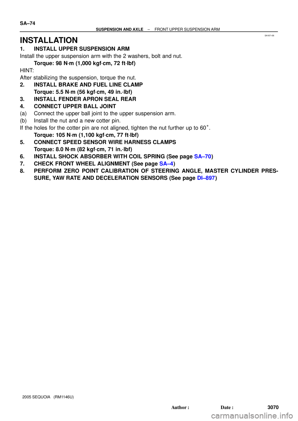
INSTALLATION
1. INSTALL UPPER SUSPENSION ARM
Install the upper suspension arm with the 2 washers, bolt and nut.
Torque: 98 N´m (1,000 kgf´cm, 72 ft´lbf)
HINT:
After stabilizing the suspension, torque the nut.
2. INSTALL BRAKE AND FUEL LINE CLAMP
Torque: 5.5 N´m (56 kgf´cm, 49 in.´lbf)
3. INSTALL FENDER APRON SEAL REAR
4. CONNECT UPPER BALL JOINT
(a) Connect the upper ball joint to the upper suspension arm.
(b) Install the nut and a new cotter pin.
If the holes for the cotter pin are not aligned, tighten the nut further up to 60°.
Torque: 105 N´m (1,100 kgf´cm, 77 ft´lbf)
5. CONNECT SPEED SENSOR WIRE HARNESS CLAMPS
Torque: 8.0 N´m (82 kgf´cm, 71 in.´lbf)
6. INSTALL SHOCK ABSORBER WITH COIL SPRING (See page SA±70)
7. CHECK FRONT WHEEL ALIGNMENT (See page SA±4)
8. PERFORM ZERO POINT CALIBRATION OF STEERING ANGLE, MASTER CYLINDER PRES-
SURE, YAW RATE AND DECELERATION SENSORS (See page DI±897)
Page 3080 of 4323
SA23X±03
R13425
SST
F07278
F07273
F14315
SA±76
± SUSPENSION AND AXLEFRONT LOWER SUSPENSION ARM
3072 Author�: Date�:
2005 SEQUOIA (RM1146U)
REMOVAL
1. REMOVE RH AND LH FRONT WHEELS
2. DISCONNECT RH AND LH TIE ROD ENDS
(a) Remove the cotter pin and nut.
(b) Using SST, disconnect the tie rod end from the lower ball
joint.
SST 09610±20012
(c) Use the same procedures described above to the other
side.
3. REMOVE POWER STEERING GEAR SET BOLTS AND
NUTS
4. DISCONNECT STABILIZER BAR LINK FROM LOWER
SUSPENSION ARM
Remove the nut and disconnect the stabilizer bar link from the
lower suspension arm.
HINT:
If the ball joint turns together with the nut, use a hexagon (6 mm)
wrench to hold the stud.
5. DISCONNECT SHOCK ABSORBER FROM LOWER
SUSPENSION ARM
(a) Remove the shock absorber lower side set nut and wash-
er.
NOTICE:
Do not remove the bolt.
(b) Pry down the lower suspension arm to remove the bolt
and disconnect the shock absorber.
Page 3084 of 4323

SA23Y±05
R13282
MatchmarksMatchmarks
F07278
AC
B SA±80
± SUSPENSION AND AXLEFRONT LOWER SUSPENSION ARM
3076 Author�: Date�:
2005 SEQUOIA (RM1146U)
INSTALLATION
1. INSTALL LOWER SUSPENSION ARM TO CHASSIS
FRAME
Install the lower suspension arm with the 2 cams, bolts and cam
plates while slightly shifting the power steering gear rearward.
Torque: 130 N´m (1,325 kgf´cm, 96 ft´lbf)
NOTICE:
Do not damage the power steering gear tubes.
HINT:
After stabilizing the suspension, align the matchmarks on the
front and rear cam plates and chassis frame, and torque the
bolts.
2. CONNECT LOWER BALL JOINT TO LOWER SUSPEN-
SION ARM
Connect the lower ball joint and install the nut and a new cotter
pin.
Torque: 159 N´m (1,621 kgf´cm, 117 ft´lbf)
If the holes for the cotter pin are not aligned, tighten the nut fur-
ther up to 60°.
3. CONNECT SHOCK ABSORBER TO LOWER SUSPEN-
SION ARM
Torque: 135 N´m (1,400 kgf´cm, 100 ft´lbf)
4. CONNECT STABILIZER BAR LINK TO LOWER SUS-
PENSION ARM
Torque: 69 N´m (700 kgf´cm, 51 ft´lbf)
HINT:
If the ball joint turns together with the nut, use a hexagon (6 mm)
wrench to hold the stud.
5. INSTALL POWER STEERING GEAR
Torque:
A bolt: 165 N´m (1,700 kgf´cm, 122 ft´lbf)
B nut: 130 N´m (1,350 kgf´cm, 96 ft´lbf)
C bolt and nut: 165 N´m (1,700 kgf´cm, 122 ft´lbf)
6. CONNECT RH AND LH TIE ROD ENDS
Connect the RH and LH tie rod ends to the lower ball joints with
the nuts and new cotter pins.
Torque: 91 N´m (930 kgf´cm, 67 ft´lbf)
If the holes for the cotter pin are not aligned, tighten the nut fur-
ther up to 60°.
7. INSTALL RH AND LH FRONT WHEELS
Torque: 110 N´m (1,150 kgf´cm, 83 ft´lbf)
8. CHECK FRONT WHEEL ALIGNMENT (See page
SA±4)
9. PERFORM ZERO POINT CALIBRATION OF STEER-
ING ANGLE, MASTER CYLINDER PRESSURE, YAW
RATE AND DECELERATION SENSORS (See page
DI±897)
Page 3091 of 4323
SA245±05
R13300
R13425
SST
R12863
SST
± SUSPENSION AND AXLEFRONT LOWER BALL JOINT
SA±87
3083 Author�: Date�:
2005 SEQUOIA (RM1146U)
REMOVAL
1. REMOVE FRONT WHEEL
2. LOOSEN 4 LOWER BALL JOINT SET BOLTS
HINT:
Do not remove the bolts.
3. DISCONNECT TIE ROD END
(a) Remove the cotter pin and nut from the tie rod end.
(b) Using SST, disconnect the tie rod end from the lower ball
joint.
SST 09610±20012
4. REMOVE LOWER BALL JOINT
(a) Remove the cotter pin and nut from the lower ball joint.
(b) Using SST, disconnect the lower ball joint from the lower
suspension arm.
SST 09628±62011
(c) Remove the 4 lower ball joint set bolts.
(d) While lifting the upper suspension arm and steering
knuckle, remove the lower ball joint.
(e) Support the upper suspension arm and steering knuckle
securely.
Page 3093 of 4323

SA247±07
± SUSPENSION AND AXLEFRONT LOWER BALL JOINT
SA±89
3085 Author�: Date�:
2005 SEQUOIA (RM1146U)
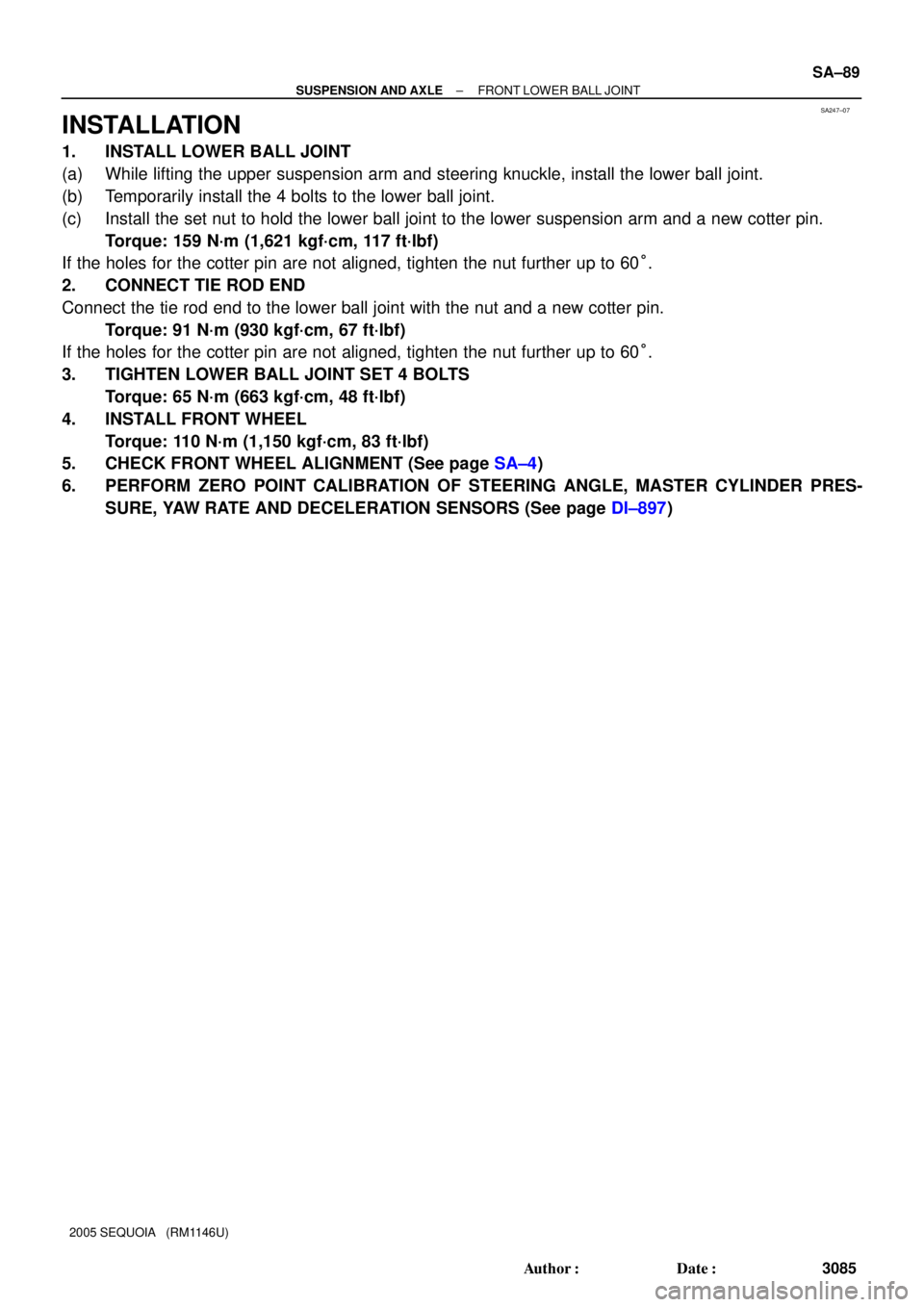
INSTALLATION
1. INSTALL LOWER BALL JOINT
(a) While lifting the upper suspension arm and steering knuckle, install the lower ball joint.
(b) Temporarily install the 4 bolts to the lower ball joint.
(c) Install the set nut to hold the lower ball joint to the lower suspension arm and a new cotter pin.
Torque: 159 N´m (1,621 kgf´cm, 117 ft´lbf)
If the holes for the cotter pin are not aligned, tighten the nut further up to 60°.
2. CONNECT TIE ROD END
Connect the tie rod end to the lower ball joint with the nut and a new cotter pin.
Torque: 91 N´m (930 kgf´cm, 67 ft´lbf)
If the holes for the cotter pin are not aligned, tighten the nut further up to 60°.
3. TIGHTEN LOWER BALL JOINT SET 4 BOLTS
Torque: 65 N´m (663 kgf´cm, 48 ft´lbf)
4. INSTALL FRONT WHEEL
Torque: 110 N´m (1,150 kgf´cm, 83 ft´lbf)
5. CHECK FRONT WHEEL ALIGNMENT (See page SA±4)
6. PERFORM ZERO POINT CALIBRATION OF STEERING ANGLE, MASTER CYLINDER PRES-
SURE, YAW RATE AND DECELERATION SENSORS (See page DI±897)
Page 3231 of 4323
BR0A3±04
F08186
BR±56
± BRAKEFRONT SPEED SENSOR
3223 Author�: Date�:
2005 SEQUOIA (RM1146U)
REMOVAL
1. REMOVE FRONT WHEEL
Torque: 110 N´m (1,122 kgf´cm, 81 ft´lbf)
2. DISCONNECT SPEED SENSOR CONNECTOR
3. REMOVE SPEED SENSOR
(a) Remove the clips and 3 clamp bolts holding the sensor
harness from the frame, upper arm and steering knuckle.
Torque: 8.0 N´m (82 kgf´cm, 71 in.´lbf)
(b) Remove the bolt and speed sensor from the steering
knuckle.
Torque: 8.0 N´m (82 kgf´cm, 71 in.´lbf)
Page 3236 of 4323

SR01S±06
± STEERINGSTEERING SYSTEM
SR±1
3228 Author�: Date�:
2005 SEQUOIA (RM1146U)
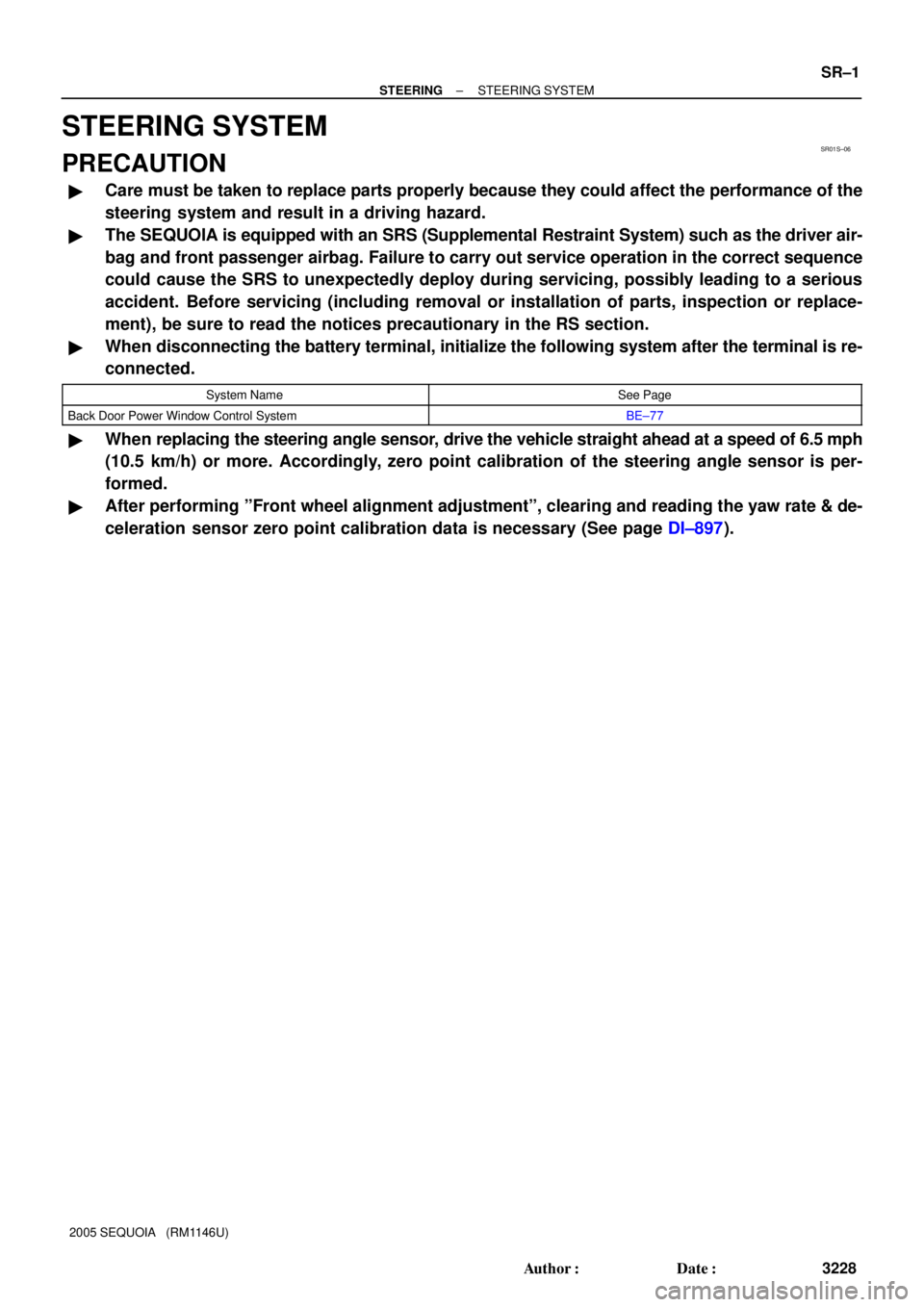
STEERING SYSTEM
PRECAUTION
�Care must be taken to replace parts properly because they could affect the performance of the
steering system and result in a driving hazard.
�The SEQUOIA is equipped with an SRS (Supplemental Restraint System) such as the driver air-
bag and front passenger airbag. Failure to carry out service operation in the correct sequence
could cause the SRS to unexpectedly deploy during servicing, possibly leading to a serious
accident. Before servicing (including removal or installation of parts, inspection or replace-
ment), be sure to read the notices precautionary in the RS section.
�When disconnecting the battery terminal, initialize the following system after the terminal is re-
connected.
System NameSee Page
Back Door Power Window Control SystemBE±77
�When replacing the steering angle sensor, drive the vehicle straight ahead at a speed of 6.5 mph
(10.5 km/h) or more. Accordingly, zero point calibration of the steering angle sensor is per-
formed.
�After performing ºFront wheel alignment adjustmentº, clearing and reading the yaw rate & de-
celeration sensor zero point calibration data is necessary (See page DI±897).
Page 3237 of 4323

SR01T±07
SR±2
± STEERINGTROUBLESHOOTING
3229 Author�: Date�:
2005 SEQUOIA (RM1146U)
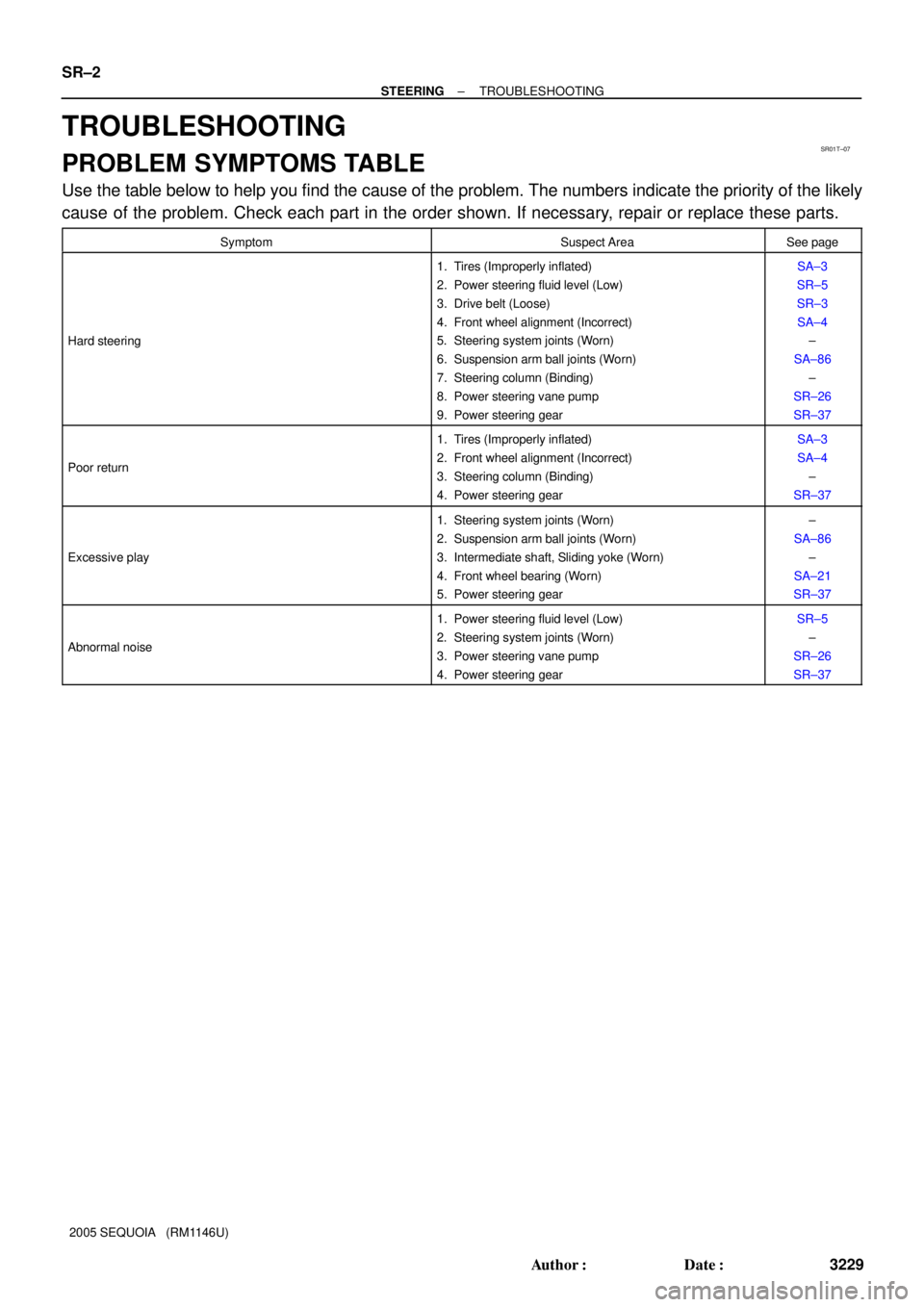
TROUBLESHOOTING
PROBLEM SYMPTOMS TABLE
Use the table below to help you find the cause of the problem. The numbers indicate the priority of the likely
cause of the problem. Check each part in the order shown. If necessary, repair or replace these parts.
SymptomSuspect AreaSee page
Hard steering
1. Tires (Improperly inflated)
2. Power steering fluid level (Low)
3. Drive belt (Loose)
4. Front wheel alignment (Incorrect)
5. Steering system joints (Worn)
6. Suspension arm ball joints (Worn)
7. Steering column (Binding)
8. Power steering vane pump
9. Power steering gearSA±3
SR±5
SR±3
SA±4
±
SA±86
±
SR±26
SR±37
Poor return
1. Tires (Improperly inflated)
2. Front wheel alignment (Incorrect)
3. Steering column (Binding)
4. Power steering gearSA±3
SA±4
±
SR±37
Excessive play
1. Steering system joints (Worn)
2. Suspension arm ball joints (Worn)
3. Intermediate shaft, Sliding yoke (Worn)
4. Front wheel bearing (Worn)
5. Power steering gear±
SA±86
±
SA±21
SR±37
Abnormal noise
1. Power steering fluid level (Low)
2. Steering system joints (Worn)
3. Power steering vane pump
4. Power steering gearSR±5
±
SR±26
SR±37