Page 1174 of 4323
F19773
ABS & VSC Actuator
(Skid Control ECU)
G±Y S14
Stop Light SW
I18 Ignition SW1 4 W
W±L
IG1
AM12
1
B±Y Instrument Panel J/B
2 1
1L
1F
1F1C
1C 1
2
46 STOP
AM1
ECU±IG W
4
B±R
Sub J/B No.3
3C8
3A8
B±R
B±R
J37AJ/C
J38AB8 Brake
Inhibit Relay
B±R L±OL±O
IL17
L±O
S1 38
BSW
STP S139
G±Y
IL2 13 12
3 4G±Y
4B1 1
14A
4C J11A
J10C J/C
CJ10G±Y G±W G±W
G±W
G±W B
J33
J34
H
G±W C
C
CJ44C
J45JR8 Rear Combination Light RH
1
4W±B
R7 Rear Combination Light LH
1
4 H9 High Mounted
Stop Light
A
A
A J19
J/C W±B
W±B
BD212
12W±B G±W
G±W
BD14
(*1) (*1)
(*2)(*2) W±B H9
High Mounted
Stop Light
1 2J57
J/C
BP BJ F10
Fusible
Link
Block ALT 8
5
B
Battery
*1: w/o Rear Spoiler
*2: w/ Rear Spoiler J/C
G±WJ/C
G±WSub J/B No.4
Stop Stop
DI±972
± DIAGNOSTICSABS WITH EBD & BA & TRAC & VSC SYSTEM
1166 Author�: Date�:
2005 SEQUOIA (RM1146U)
WIRING DIAGRAM
Page 1175 of 4323
F13968
ON
1
3
± DIAGNOSTICSABS WITH EBD & BA & TRAC & VSC SYSTEM
DI±973
1167 Author�: Date�:
2005 SEQUOIA (RM1146U)
INSPECTION PROCEDURE
1 Check voltage between terminals 1 and 3 of the brake inhibit relay and body
ground.
PREPARATION:
Remove the brake inhibit relay from the connector.
CHECK:
(a) Turn the ignition switch to the ON position.
(b) Measure the voltage between terminal 1 of the brake in-
hibit relay harness side connector and body ground.
OK:
Voltage: 10 to 14 V
CHECK:
Measure the voltage between terminal 3 of the brake inhibit
relay harness side connector and body ground when the brake
pedal is depressed.
OK:
Voltage: 8 to 14 V
NG Check and repair harness or connector.
OK
Page 1176 of 4323
F17285
1
2 34
1
4
3
2
DI±974
± DIAGNOSTICSABS WITH EBD & BA & TRAC & VSC SYSTEM
1168 Author�: Date�:
2005 SEQUOIA (RM1146U)
2 Check brake inhibit relay.
CHECK:
Check continuity between the following terminals of the brake
inhibit relay.
OK:
Terminals 1 and 2Continuity
(Reference value 62 W)
Terminals 3 and 4Continuity
CHECK:
(a) Apply battery positive voltage between terminals 1 and 2.
(b) Check continuity between terminals.
Terminals 3 and 4Open
NG Replace brake inhibit relay.
OK
3 Check for open and short circuit in harness and connector between brake inhibit
relay and skid control ECU (See page IN±35).
NG Repair or replace harness or connector.
OK
If the same code is still indicated after the DTC is deleted, check the condition of each connection.
If the connections are normal, the skid control ECU may be defective.
NOTICE:
When replacing the skid control ECU, perform the zero point calibration (See page DI±897).
Page 1177 of 4323
± DIAGNOSTICSABS WITH EBD & BA & TRAC & VSC SYSTEM
DI±975
1169 Author�: Date�:
2005 SEQUOIA (RM1146U)
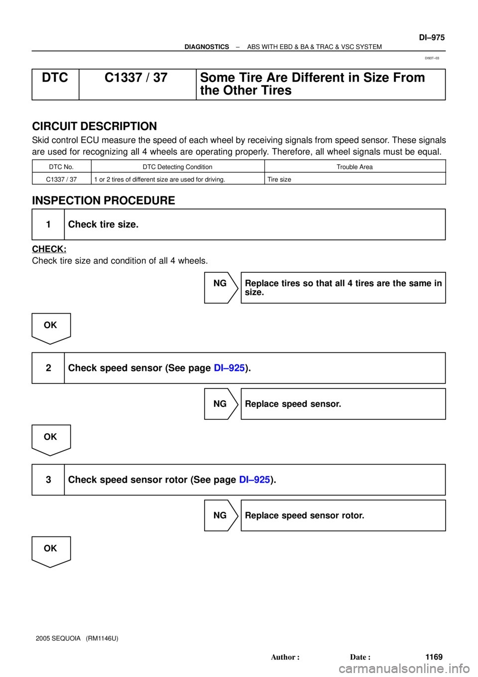
DTC C1337 / 37 Some Tire Are Different in Size From
the Other Tires
CIRCUIT DESCRIPTION
Skid control ECU measure the speed of each wheel by receiving signals from speed sensor. These signals
are used for recognizing all 4 wheels are operating properly. Therefore, all wheel signals must be equal.
DTC No.DTC Detecting ConditionTrouble Area
C1337 / 371 or 2 tires of different size are used for driving.Tire size
INSPECTION PROCEDURE
1 Check tire size.
CHECK:
Check tire size and condition of all 4 wheels.
NG Replace tires so that all 4 tires are the same in
size.
OK
2 Check speed sensor (See page DI±925).
NG Replace speed sensor.
OK
3 Check speed sensor rotor (See page DI±925).
NG Replace speed sensor rotor.
OK
DI93T±03
Page 1178 of 4323
DI±976
± DIAGNOSTICSABS WITH EBD & BA & TRAC & VSC SYSTEM
1170 Author�: Date�:
2005 SEQUOIA (RM1146U)
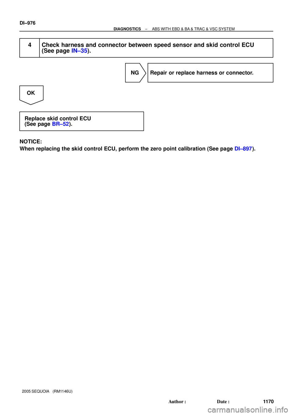
4 Check harness and connector between speed sensor and skid control ECU
(See page IN±35).
NG Repair or replace harness or connector.
OK
Replace skid control ECU
(See page BR±52).
NOTICE:
When replacing the skid control ECU, perform the zero point calibration (See page DI±897).
Page 1179 of 4323
± DIAGNOSTICSABS WITH EBD & BA & TRAC & VSC SYSTEM
DI±977
1171 Author�: Date�:
2005 SEQUOIA (RM1146U)
DTC C1340 / 47 Center DIFF. Lock Circuit Malfunction
CIRCUIT DESCRIPTION
This circuit sends the signal to the ECU by detecting that the transfer center differential is in the ºLOCKº posi-
tion.
DTC No.DTC Detecting ConditionTrouble Area
C1340 / 47Center diff. lock position switch signal does not change
�Center diff. lock position switch
�Center diff. lock position switch circuit
�Center diff. lock Indicator light circuit
�Translate ECU
DIDMD±01
Page 1180 of 4323
F19774
Translate Shift ActuatorABS & VSC Actuator
(Skid Control ECU)
VSC±
CD
EXI2
CSW VSC+7
T5
11
T5
29
T5
31
T5
26
T5LL
W
BR±Y (4WD)W 7
IL2
6
IL26
S1
2
S1CANH
CANL
Sub J/B No.3
Y±G (4WD)
BR±Y9
3C9
3A
9
3BA10
ADD Actuator
ADDGND
BR±Y Sub J/B No.4
8
4B
7
4A7
4B8
4AL±W
L±W
(4WD)
4WD
Control ECU
4
F23
16
F23
20
F23
11
F23
19
F23
3
F23
6
F23 DL
IND2
IG ADDP1
IND3
IND1Y±B
L±W
BR±Y
L±W
BR±YBR±Y
BR±Y
G±W
Y±B
GR
B±YC6
Combination Meter
Center Diff. Lock
4LO
4HI
24B±OGR GR
GR
GR
W±B
W±B
W±B
W±B
W±B W±B
1
3
D
BEC1
EB5
J51
J526
4EC1
EB5
A
A
A
J41
J/C
IG4 21 B±Y
Instrument Panel J/B I18
Ignition SW
B±O
W±R
W B±Y
B±R
W±R
W±L W±L
W±R4WD
IGN1
AM1 AM1IG1
AM2IG22
64
1C
2
1C
3
1C
6
1C8
1D
11
1H
7
1J
1
1L
12
3
4 J/C
1 2 1
54
5 634 DI±978
± DIAGNOSTICSABS WITH EBD & BA & TRAC & VSC SYSTEM
1172 Author�: Date�:
2005 SEQUOIA (RM1146U)
WIRING DIAGRAM
Page 1181 of 4323
F19775
TL1
TL2
TL325
F22
24
F22
23
F22B±W
B
B±RB±W
B
B±R W±B 6
IG1
9
IG1
2
IG1TL1
TL2
TL3 GND T4
Transfer Shift Actuator12
3
4
W±BW±B
W±R W
W±R W
A
J18
J/C 5
6
F10
Fusible Link Block
ALT
5
48
B BEngine Room J/B
1
2D1
2C AM2
IG Battery3
4
± DIAGNOSTICSABS WITH EBD & BA & TRAC & VSC SYSTEM
DI±979
1173 Author�: Date�:
2005 SEQUOIA (RM1146U)

G±Y S14
Stop Light SW
I18 Ignition SW1 4 W
W±L
IG1
AM12
1
B±Y Instrument Panel J/B
2 1
1L
1F
1F1C
1C 1
2
46 STOP
AM1
ECU±IG W
4
B±R
Sub J/B No.3
3C8")


VSC±
CD
EXI2
CSW VSC+7
T5
11
T5
29
T5
31
T5
26
T5LL
W
BR±Y (4WD)W 7
IL2
6
IL26
S1
2
S1CANH
CANL
Sub J/B No.3
Y±G (4WD)
BR±Y9
3")
