Page 1158 of 4323
F19145
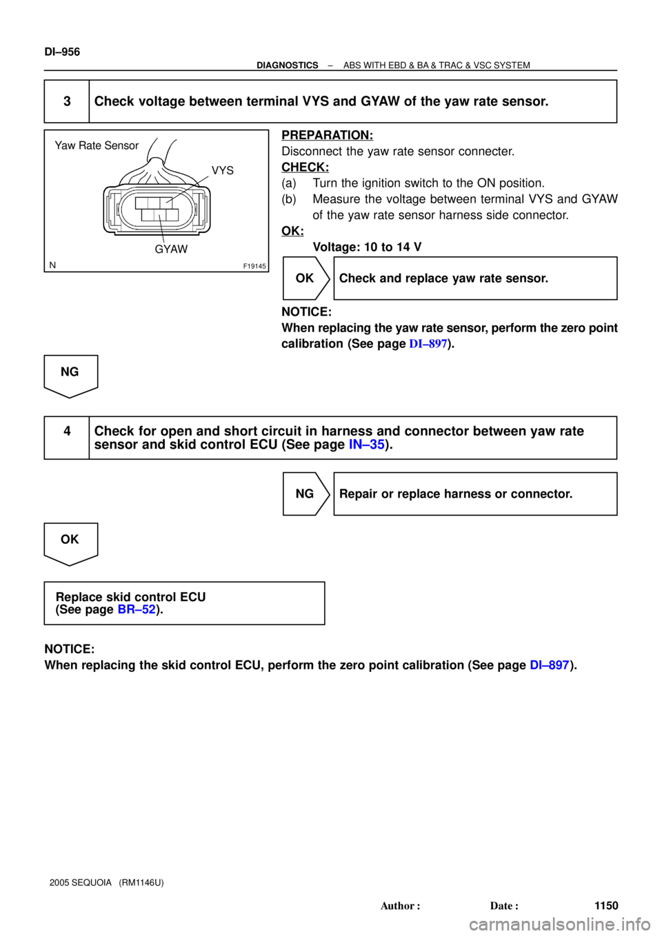
Yaw Rate Sensor
VYS
GYAW
DI±956
± DIAGNOSTICSABS WITH EBD & BA & TRAC & VSC SYSTEM
1150 Author�: Date�:
2005 SEQUOIA (RM1146U)
3 Check voltage between terminal VYS and GYAW of the yaw rate sensor.
PREPARATION:
Disconnect the yaw rate sensor connecter.
CHECK:
(a) Turn the ignition switch to the ON position.
(b) Measure the voltage between terminal VYS and GYAW
of the yaw rate sensor harness side connector.
OK:
Voltage: 10 to 14 V
OK Check and replace yaw rate sensor.
NOTICE:
When replacing the yaw rate sensor, perform the zero point
calibration (See page DI±897).
NG
4 Check for open and short circuit in harness and connector between yaw rate
sensor and skid control ECU (See page IN±35).
NG Repair or replace harness or connector.
OK
Replace skid control ECU
(See page BR±52).
NOTICE:
When replacing the skid control ECU, perform the zero point calibration (See page DI±897).
Page 1159 of 4323
F19782
Battery16
S1+BS
GND1
GND2
+BM S1
S1 S1 47
1
32 B±R
B±R
W±B
W±B W±B W±B 5 BF10
Fusible Link BlockABS & VSC Actuator
(Skid Control ECU)
IG J18
J/C
A A3
ABS
Motor Relay
Pump
Motor IL117
IL19
± DIAGNOSTICSABS WITH EBD & BA & TRAC & VSC SYSTEM
DI±957
1151 Author�: Date�:
2005 SEQUOIA (RM1146U)
DTC C1241 / 41 Power Source Circuit
CIRCUIT DESCRIPTION
If there is a problem with the skid control ECU power supply circuit, the skid control ECU outputs DTC and
prohibits operation under the fail safe function.
DTC No.DTC Detecting ConditionTrouble Area
C1241 / 41
When any of the following conditions are detected:
1. ECU terminal +BM/+BS voltage is too low for a fixed
time during driving.
2. ECU terminal +BM/+BS voltage is too high for a fixed
time while ignition switch is ON.�Battery
�Charging system
�Power source circuit (+BM, +BS)
�Skid control ECU
WIRING DIAGRAM
DIDMA±01
Page 1160 of 4323
DI±958
± DIAGNOSTICSABS WITH EBD & BA & TRAC & VSC SYSTEM
1152 Author�: Date�:
2005 SEQUOIA (RM1146U)
INSPECTION PROCEDURE
1 Check ABS fuse.
PREPARATION:
Remove the ABS fuse from the fusible link block.
CHECK:
Check continuity of the ABS fuse.
OK:
Continuity
NG Check for short circuit in all the harnesses and
components connected to ABS fuse (See at-
tached wiring diagram).
OK
2 Check battery positive voltage.
OK:
Voltage: 10 to 14 V
NG Check and repair the charging system
(See page CH±1).
OK
Page 1161 of 4323
F16988
GND+BM
+BS
F16991
GND
± DIAGNOSTICSABS WITH EBD & BA & TRAC & VSC SYSTEM
DI±959
1153 Author�: Date�:
2005 SEQUOIA (RM1146U)
3 Check voltage of the +BM/+BS power source.
PREPARATION:
Disconnect the skid control ECU connector.
CHECK:
Measure the voltage between terminal +BM/+BS and GND of
the skid control ECU harness side connector.
OK:
Voltage: 10 to 14 V
OK Replace skid control ECU
(See page BR±52).
NOTICE:
When replacing the skid control ECU, perform the zero
point calibration (See page DI±897).
NG
4 Check continuity between terminal GND of the skid control ECU connector and
body ground (See page IN±35).
PREPARATION:
Disconnect the skid control ECU connector.
CHECK:
Measure the resistance between terminal GND of the skid con-
trol ECU harness side connector and body ground.
OK:
Resistance: 1 W or less
NG Repair or replace harness or connector.
OK
Check for open circuit in harness and connector between skid control ECU and battery
(See page IN±35).
Page 1162 of 4323
F16976
ABS & VSC Actuator
(Skid Control ECU) P20
Pedal Stroke Speed Sensor
(Delta S Sensor)
(Shielded)
Instrument Panel J/BVCP
PIM
E3 S1 3
BR
J28
J/C
A
IEVCP1
S1
S1 8 14
PIM
E3
A
A J8
J/C
W±B W±B
1F
1K12 9 5
3G
Y
L DI±960
± DIAGNOSTICSABS WITH EBD & BA & TRAC & VSC SYSTEM
1154 Author�: Date�:
2005 SEQUOIA (RM1146U)
DTC C1247 / 47 Malfunction in Delta S Sensor
CIRCUIT DESCRIPTION
Detects a problem with booster negative pressure and enters assist control.
DTC No.DTC Detecting ConditionTrouble Area
C1247 / 47
When any of the following conditions are detected:
1. When the output becomes 4.7 V or more or 0.2 V or less
per 100 msec.
2. When the output does not return to 2.5 V even when 500
msec. or more elapse, in spite of no change in brake
operation.
�Brake booster
�Delta S sensor (Pedal stroke speed sensor)
�Delta S sensor (Pedal stroke speed sensor) circuit
�Skid control ECU
WIRING DIAGRAM
DIDMB±01
Page 1163 of 4323
: Brake Pedal
Depressed
(2): Brake Pedal
Released Voltage
Time 4.5 V
1.9 V
0.5 V(2)
(1)
± DIAGNOSTICSABS WITH EBD & BA & TRAC & VSC SYSTEM
DI±961
1155 Author�: Date�:
2005 SEQUOIA (RM11")
F19800
(1): Brake Pedal
Depressed
(2): Brake Pedal
Released Voltage
Time 4.5 V
1.9 V
0.5 V(2)
(1)
± DIAGNOSTICSABS WITH EBD & BA & TRAC & VSC SYSTEM
DI±961
1155 Author�: Date�:
2005 SEQUOIA (RM1146U)
INSPECTION PROCEDURE
HINT:
Start the inspection from step 1 in the case of using the hand±held tester and start from step 2 in the case
of not using the hand±held tester.
1 Check output value of the delta S sensor (pedal stroke speed sensor) using the
hand±held tester.
PREPARATION:
(a) Connect the hand±held tester to the DLC3.
(b) Turn the ignition switch to the ON position.
(c) Run the engine until the engine speed reaches 3,000 rpm, and return it back to idle.
HINT:
Rev up the engine to ensure sufficient vacuum.
(d) Select DATA LIST mode on the hand±held .
ItemMeasurement Item /
Range (Display)Normal ConditionDiagnostic Note
PEDAL STROKEPedal stroke sensor/
min.: 0 V, max.: 5.1 V
Approximately 2.0 V with-
out the brake pedal de-
pressed.
±
HINT:
�The result appears on the tester after some delay because a time lag occurs in measurement with a
hand±held tester.
�If a signal from the delta S sensor is sent between sampling, the result does not appear on the tester.
So be sure to perform the measurement 2 or 3 times.
CHECK:
Check that the brake pedal acceleration value of the delta S sensor displayed on the hand±held tester
changes, alternatively increasing the brake pedal stroke.
OK:
The value changes as shown in the illustration on the
left. (The value will return to approximately 2.0 V after
the brake pedal is released.)
HINT:
The maximum voltage depends on pedal stroke speed but
should not exceed 4.5 V or fall below 0.2 V.
OK Replace skid control ECU
(See page BR±52).
NOTICE:
When replacing the skid control ECU, perform zero point
calibration (See page DI±897).
NG
Page 1164 of 4323
F19145
Delta S Sensor
(Pedal Stroke
Speed Sensor
VCP
DI±962
± DIAGNOSTICSABS WITH EBD & BA & TRAC & VSC SYSTEM
1156 Author�: Date�:
2005 SEQUOIA (RM1146U)
2 Check for open or short circuit in harness and connector between delta S sensor
(pedal stroke speed sensor) and skid control ECU (See page IN±35).
NG Repair or replace harness or connector.
OK
3 Inspect the delta S sensor (pedal stroke speed sensor ) terminal voltage (VCP
terminal)
PREPARATION:
Disconnect the delta S sensor (pedal stroke speed sensor) con-
nector.
CHECK:
(a) Turn the ignition switch to the ON position.
(b) Measure the voltage between VCP terminal and body
ground.
OK:
Voltage: 5 V
NG Replace skid control ECU
(See page BR±52).
NOTICE:
When replacing the skid control ECU, perform zero point
calibration (See page DI±897).
OK
Replace brake booster (See page BR±22).
Page 1165 of 4323
± DIAGNOSTICSABS WITH EBD & BA & TRAC & VSC SYSTEM
DI±963
1157 Author�: Date�:
2005 SEQUOIA (RM1146U)
DTC C1249 / 49 Open Circuit in Stop Light Switch Cir-
cuit
CIRCUIT DESCRIPTION
The skid control ECU inputs the stop light switch signal and detects the status of the brake operation.
The skid control ECU has an open detection circuit. If an open in the stop lamp switch input line or GND side
stop lamp circuit is detected when the stop lamp switch is off, this DTC is output.
DTC No.DTC Detecting ConditionTrouble Area
C1249 / 49ECU terminal STP voltage is low when both ignition switch
and stop light switch are ON.�Stop light switch
�Stop light switch circuit
�Skid control ECU
DI93P±03

IG J18
J/C
A A3
ABS
Motor Relay
Pump
Motor IL117
IL19")


 P20
Pedal Stroke Speed Sensor
(Delta S Sensor)
(Shielded)
Instrument Panel J/BVCP
PIM
E3 S1 3
BR
J28
J/C
A
IEVCP1
S1
S1 8 14
PIM
E3
A
A J8
J/C
W±B W±B
1F")