Page 1126 of 4323
DI±924
± DIAGNOSTICSABS WITH EBD & BA & TRAC & VSC SYSTEM
111 8 Author�: Date�:
2005 SEQUOIA (RM1146U)
If the brake warning light turns on, check that the parking brake pedal is released, the brake fluid level is
normal, and no malfunction is identified in the fluid level warning switch system.
If there is a problem with VSC, the brake warning light comes on. The possible causes of a problem are as
follows:
�2 or more wheel speed sensor failures
�Low/high voltage
�Valve failure
Page 1127 of 4323

DI93G±05
BR3583
BR3582F00010
RotorSpeed Sensor
Magnet
To ECU
+V
±VHigh Speed
Low Speed
CoilNS
± DIAGNOSTICSABS WITH EBD & BA & TRAC & VSC SYSTEM
DI±925
111 9 Author�: Date�:
2005 SEQUOIA (RM1146U)
CIRCUIT INSPECTION
DTC
C0200 / 31 ± C0215 / 34Speed Sensor Circuit
CIRCUIT DESCRIPTION
The speed sensor detects wheel speed and sends the ap-
propriate signals to the ECU. These signals are used to control
the ABS control system. The front and rear rotors have 48
serrations each.
When the rotors rotate, the magnetic field emitted by the perma-
nent magnet in the speed sensor generates AC voltage. Since
the frequency of this AC voltage changes in direct proportion to
the speed of the rotor, the frequency is used by the ECU to de-
tect the speed of each wheel.
DTC No.DTC Detecting ConditionTrouble Area
C0200 / 31
C0205 / 32
C0210 / 33
C0215 / 34
When any of the following is detected:
1. During driving, speed sensor signals are not input for a
fixed time.
2. Momentary interruption in speed sensor signals occurs
many times during driving.
3. Abnormal signal occurs in pulse signal from speed sen-
sor during driving.
4. Speed sensor signal circuit continues to be open for a
fixed time.
�Right front, left front, right rear and left rear speed sensor
�Each speed sensor circuit
�Sensor rotor
�Skid control ECU
HINT:
DTC No. C0200 / 31 is for the right front speed sensor.
DTC No. C0205 / 32 is for the left front speed sensor.
DTC No. C0210 / 33 is for the right rear speed sensor.
DTC No. C0215 / 34 is for the left rear speed sensor.
Page 1128 of 4323
F19767
ABS & VSC Actuator
(Skid Control ECU)
A7
ABS Speed Sensor
Front RH
33 46
34 2
1
12FL±FR±
RR+FL+
RR±RL+
RL± 2
1FR+ S1
S1
S1
S1
S1
S1
S1
S142
43
36 37
1 2 A32
ABS Speed Sensor
Rear LH
A33
ABS Speed Sensor
Rear RHA6
ABS Speed Sensor
Front LH45 V
P
L
LG
G G G
G
R±B R±B R±B
R±B BB26
IL114
BB2
BB2
BB2IL1
IL1
IL113 5
8
7O O O O
YY
YY 6
5 IJ32
IJ3 13
IJ31
IJ3 12 DI±926
± DIAGNOSTICSABS WITH EBD & BA & TRAC & VSC SYSTEM
1120 Author�: Date�:
2005 SEQUOIA (RM1146U)
WIRING DIAGRAM
Page 1129 of 4323

INSPECTION PROCEDURE
HINT:
Start the inspection from step 1 when using the hand±held tester a")
± DIAGNOSTICSABS WITH EBD & BA & TRAC & VSC SYSTEM
DI±927
1121 Author�: Date�:
2005 SEQUOIA (RM1146U)
INSPECTION PROCEDURE
HINT:
Start the inspection from step 1 when using the hand±held tester and start from step 2 when not using the
hand±held tester.
1 Check output value of speed sensor.
PREPARATION:
(a) Connect the hand±held tester to the DLC3.
(b) Turn the ignition switch to the ON position and push the hand±held tester main switch ON.
(c) Select DATA LIST mode on the hand±held tester.
CHECK:
Check that there is no difference between the speed value output from the speed sensor displayed by the
hand±held tester and the speed value displayed by the speedometer when driving the vehicle.
ItemMeasurement Item /
Range (Display)Normal ConditionDiagnostic Note
WHEEL SPD FR
Wheel speed sensor (FR)
reading / min.: 0 MPH (0
km/h), max.: 202 MPH
(326 km/h)
Actual wheel speedSimilar speed as indicated
on speedometer
WHEEL SPD FL
Wheel speed sensor (FR)
reading / min.: 0 MPH (0
km/h), max.: 202 MPH
(326 km/h)
Actual wheel speedSimilar speed as indicated
on speedometer
WHEEL SPD RR
Wheel speed sensor (FR)
reading / min.: 0 MPH (0
km/h), max.: 202 MPH
(326 km/h)
Actual wheel speedSimilar speed as indicated
on speedometer
WHEEL SPD RL
Wheel speed sensor (FR)
reading / min.: 0 MPH (0
km/h), max.: 202 MPH
(326 km/h)
Actual wheel speedSimilar speed as indicated
on speedometer
OK:
There is almost no difference from the displayed speed value.
HINT:
There is tolerance of + 10 % in the speedometer indication.
OK Go to step 4.
NG
Page 1130 of 4323

2 Check speed sensor.
Front:
PREPARATION:
(a) Make sure that there is no l")
R14205
21
R14205
21
DI±928
± DIAGNOSTICSABS WITH EBD & BA & TRAC & VSC SYSTEM
1122 Author�: Date�:
2005 SEQUOIA (RM1146U)
2 Check speed sensor.
Front:
PREPARATION:
(a) Make sure that there is no looseness at the connector
lock part and connecting part of the connector.
(b) Disconnect the speed sensor connector.
CHECK:
Measure the resistance between terminals 1 and 2 of the speed
sensor connector.
OK:
Resistance: 0.92 to 1.22 kW
CHECK:
Measure the resistance between terminals 1 and 2 of the speed
sensor connector and body ground.
OK:
Resistance: 1 MW or higher
Rear:
PREPARATION:
(a) Make sure that there is no looseness at the connector
lock part and connecting part of the connector.
(b) Disconnect the speed sensor connector.
CHECK:
Measure the resistance between terminals 1 and 2 of the speed
sensor connector.
OK:
Resistance: 1.8 to 2.2 kW
CHECK:
Measure the resistance between terminals 1 and 2 of the speed
sensor connector and body ground.
OK:
Resistance: 1 MW or higher
NG Replace speed sensor
(See page BR±56 or BR±59).
NOTICE:
Check the speed sensor signal after replacement (See
page DI±899).
OK
Page 1131 of 4323
BR3795OKNG
± DIAGNOSTICSABS WITH EBD & BA & TRAC & VSC SYSTEM
DI±929
1123 Author�: Date�:
2005 SEQUOIA (RM1146U)
3 Check for open and short circuit in harness and connector between each speed
sensor and skid control ECU (See page IN±35).
NG Repair or replace harness or connector.
OK
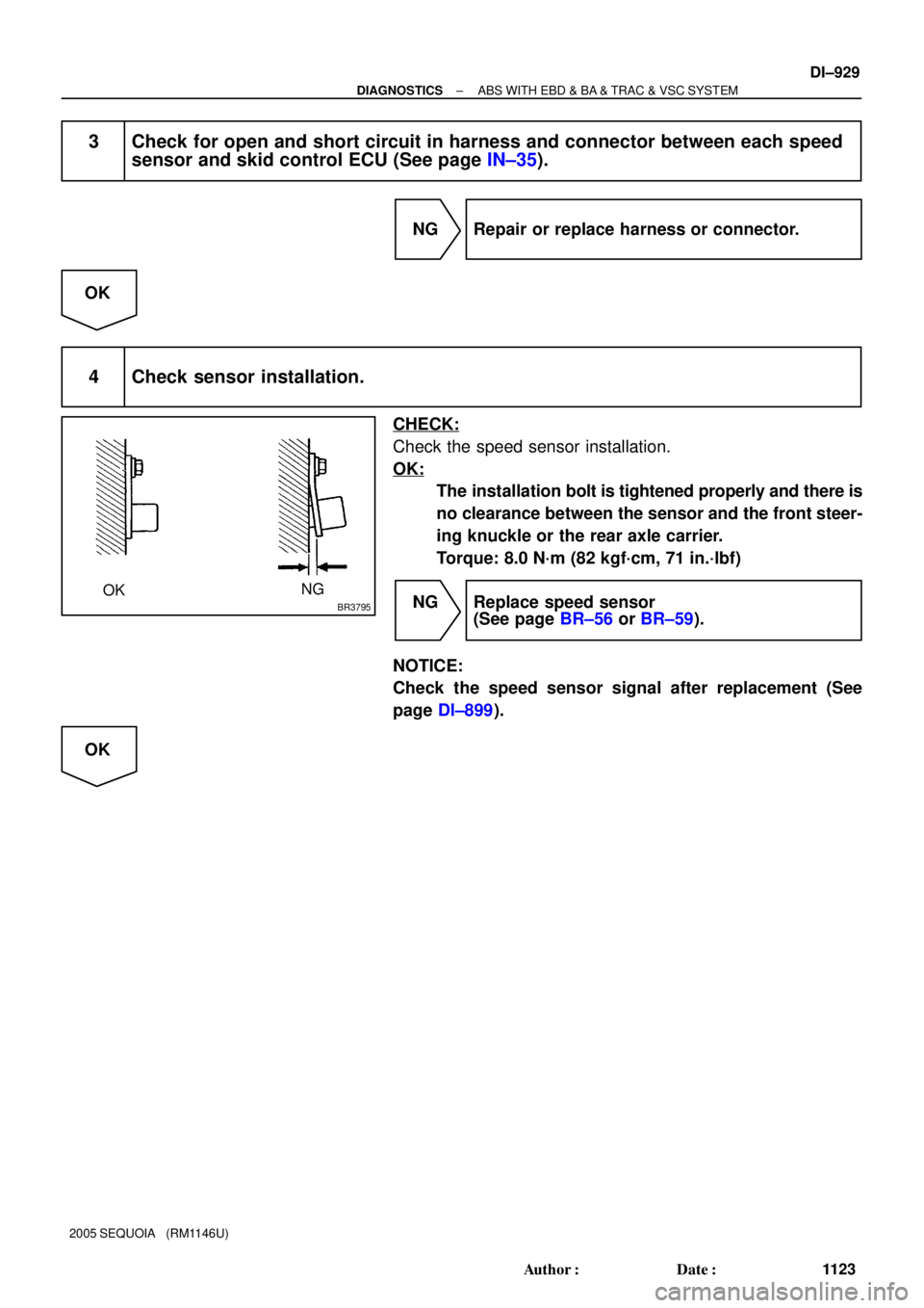
4 Check sensor installation.
CHECK:
Check the speed sensor installation.
OK:
The installation bolt is tightened properly and there is
no clearance between the sensor and the front steer-
ing knuckle or the rear axle carrier.
Torque: 8.0 N´m (82 kgf´cm, 71 in.´lbf)
NG Replace speed sensor
(See page BR±56 or BR±59).
NOTICE:
Check the speed sensor signal after replacement (See
page DI±899).
OK
Page 1132 of 4323

5 Check speed sensor an")
W04200
Normal Signal Waveform
1 V / Division2 m/s / DivisionGND
R07880
DI±930
± DIAGNOSTICSABS WITH EBD & BA & TRAC & VSC SYSTEM
1124 Author�: Date�:
2005 SEQUOIA (RM1146U)
5 Check speed sensor and sensor rotor serrations.
INSPECTION USING OSCILLOSCOPE
PREPARATION:
Connect the oscilloscope to the terminal FR+ ± FR±, FL+ ± FL±,
RR+ ± RR± and RL+ ± RL± of the skid control ECU.
CHECK:
Drive the vehicle at about 12 mph (20 km/h), and check the sig-
nal waveform.
OK:
A waveform as shown in the figure should be output.
HINT:
�As the vehicle speed (wheel revolution speed) increases,
a cycle of the waveform becomes shorter and the fluctua-
tion in the output voltage becomes greater.
�When noise is identified in the waveform on the oscillo-
scope, error signals are generated due to the speed sen-
sor rotor's scratches, looseness or foreign matter depos-
ited on it.
OK Replace skid control ECU
(See page BR±52).
NOTICE:
When replacing the skid control ECU, perform the zero
point calibration (See page DI±897).
NG
6 Check sensor rotor and sensor tip.
Front:
PREPARATION:
Remove the disc (See page SA±22).
CHECK:
Check the sensor rotor serrations.
OK:
No scratches, missing teeth or foreign objects.
PREPARATION:
Remove the front speed sensor (See page BR±56).
CHECK:
Check the sensor tip.
OK:
No scratches or foreign objects on the sensor tip.
HINT:
Remove any foreign matter if identified.
Check the output waveform again after reassembly.
Page 1133 of 4323
W02871
± DIAGNOSTICSABS WITH EBD & BA & TRAC & VSC SYSTEM
DI±931
1125 Author�: Date�:
2005 SEQUOIA (RM1146U)
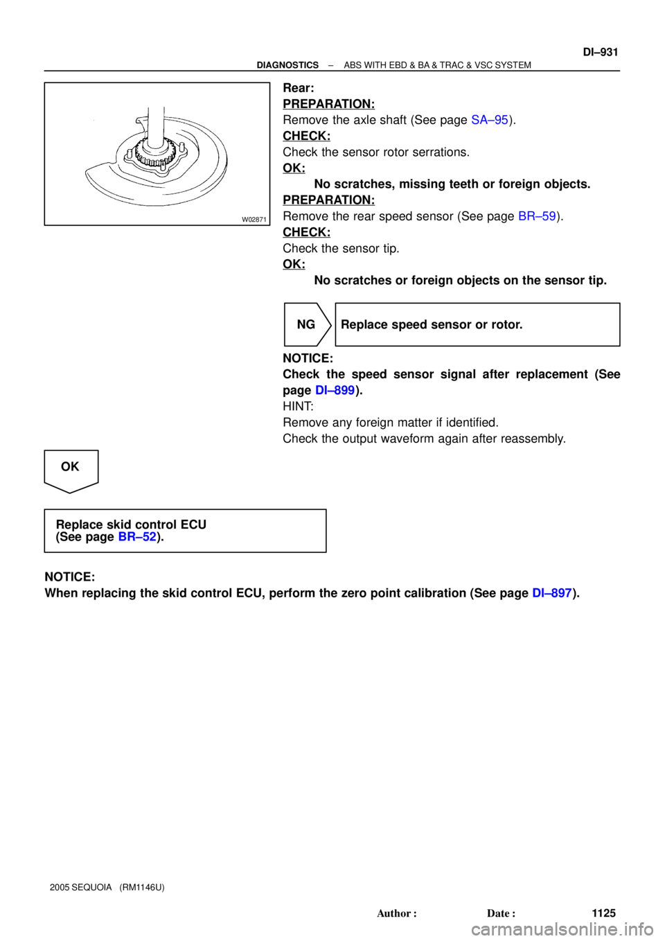
Rear:
PREPARATION:
Remove the axle shaft (See page SA±95).
CHECK:
Check the sensor rotor serrations.
OK:
No scratches, missing teeth or foreign objects.
PREPARATION:
Remove the rear speed sensor (See page BR±59).
CHECK:
Check the sensor tip.
OK:
No scratches or foreign objects on the sensor tip.
NG Replace speed sensor or rotor.
NOTICE:
Check the speed sensor signal after replacement (See
page DI±899).
HINT:
Remove any foreign matter if identified.
Check the output waveform again after reassembly.
OK
Replace skid control ECU
(See page BR±52).
NOTICE:
When replacing the skid control ECU, perform the zero point calibration (See page DI±897).


A7
ABS Speed Sensor
Front RH
33 46
34 2
1
12FL±FR±
RR+FL+
RR±RL+
RL± 2
1FR+ S1
S1
S1
S1
S1
S1
S1
S142
43
36 37
1 2 A32
ABS Speed Sensor
Rear LH
A33
ABS")