Page 1134 of 4323
F19768
F10
Fusible Link Block
ABS
B
5
3B±R47
S1
W±B17
IL1W±B1
S1
W±BW±B A
A
J18
J/C
Battery
IG9
IL132
S1+BS
GND2ABS&VSC Actuator (Skid Control ECU)
IFL
IFR
IRL
IRR
OFL
OFR
ORL
ORR
ASR1
SV1
SV2
BATT ASR2 GND1Skid Control ECU DI±932
± DIAGNOSTICSABS WITH EBD & BA & TRAC & VSC SYSTEM
1126 Author�: Date�:
2005 SEQUOIA (RM1146U)
DTC C0226 / 21 ABS & VSC Solenoid Circuit
CIRCUIT DESCRIPTION
This solenoid turns on when signals are received from the ECU and controls the pressure acting on the wheel
cylinders to control braking force.
DTC No.DTC Detecting ConditionTrouble Area
C0226 / 21Solenoid valve signal does not match the check result.�ABS & VSC actuator
�ABS & VSC solenoid circuit
WIRING DIAGRAM
DI93H±03
Page 1135 of 4323
± DIAGNOSTICSABS WITH EBD & BA & TRAC & VSC SYSTEM
DI±933
1127 Author�: Date�:
2005 SEQUOIA (RM1146U)
INSPECTION PROCEDURE
1 Check DTC once more (See page DI±911).
PREPARATION:
(a) Clear the DTC.
(b) Turn the ignition switch OFF.
CHECK:
Turn the ignition switch to the ON position, and check if the same DTC still remains in the memory.
RESULT:
DTC is outputA
DTC is not outputB
B No problem.
A
Replace skid control ECU with actuator
(See page BR±51).
NOTICE:
When replacing the skid control ECU, perform the zero point calibration (See page DI±897).
Page 1136 of 4323
F19782
Battery16
S1+BS
GND1
GND2
+BM S1
S1 S1 47
1
32 B±R
B±R
W±B
W±B W±B W±B 5 BF10
Fusible Link BlockABS & VSC Actuator
(Skid Control ECU)
IG J18
J/C
A A3
ABS
Motor Relay
Pump
Motor IL117
IL19 DI±934
± DIAGNOSTICSABS WITH EBD & BA & TRAC & VSC SYSTEM
1128 Author�: Date�:
2005 SEQUOIA (RM1146U)
DTC C0278 / 11 ABS & VSC Relay Circuit
CIRCUIT DESCRIPTION
This relay supplies power to each ABS & VSC solenoid. If the initial check is OK, then the relay turns on after
the ignition switch is turned ON.
DTC No.DTC Detecting ConditionTrouble Area
C0278 / 11Relay circuit continues to be open for a fixed time when
solenoid relay is ON after ignition switch is turned ON.
�ABS & VSC solenoid relay
�ABS & VSC solenoid relay circuit
�ABS & VSC motor relay
�ABS & VSC motor relay circuit
WIRING DIAGRAM
DI93I±03
Page 1137 of 4323
F16988
GND
+BM
+BS
± DIAGNOSTICSABS WITH EBD & BA & TRAC & VSC SYSTEM
DI±935
1129 Author�: Date�:
2005 SEQUOIA (RM1146U)
INSPECTION PROCEDURE
1 Check voltage between terminals +BS, +BM and GND of the skid control ECU
connector.
PREPARATION:
Disconnect the skid control ECU connector.
CHECK:
Measure the voltage between terminals +BS, +BM and GND of
the skid control ECU harness side connector.
OK:
Voltage: 10 to 14 V
NG Check and replace ABS fuses.
Check and repair harness or connector.
OK
If the same code is still indicated after the DTC is deleted, check the condition of each connection.
If the connections are normal, the skid control ECU may be defective.
NOTICE:
When replacing the skid control ECU, perform the zero point calibration (See page DI±897).
Page 1138 of 4323
DI±936
± DIAGNOSTICSABS WITH EBD & BA & TRAC & VSC SYSTEM
1130 Author�: Date�:
2005 SEQUOIA (RM1146U)
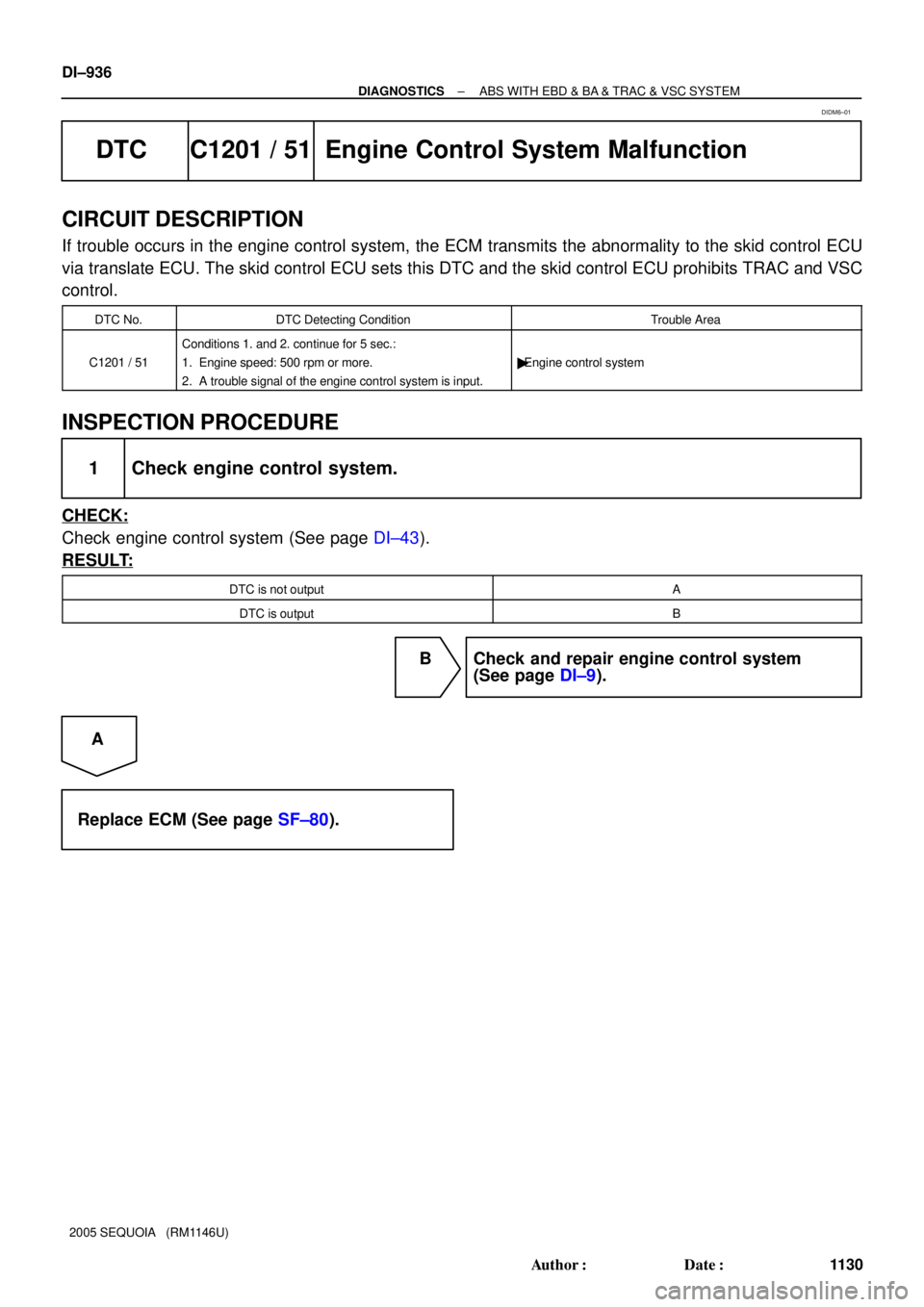
DTC C1201 / 51 Engine Control System Malfunction
CIRCUIT DESCRIPTION
If trouble occurs in the engine control system, the ECM transmits the abnormality to the skid control ECU
via translate ECU. The skid control ECU sets this DTC and the skid control ECU prohibits TRAC and VSC
control.
DTC No.DTC Detecting ConditionTrouble Area
C1201 / 51
Conditions 1. and 2. continue for 5 sec.:
1. Engine speed: 500 rpm or more.
2. A trouble signal of the engine control system is input.
�Engine control system
INSPECTION PROCEDURE
1 Check engine control system.
CHECK:
Check engine control system (See page DI±43).
RESULT:
DTC is not outputA
DTC is outputB
B Check and repair engine control system
(See page DI±9).
A
Replace ECM (See page SF±80).
DIDM6±01
Page 1139 of 4323
± DIAGNOSTICSABS WITH EBD & BA & TRAC & VSC SYSTEM
DI±937
1131 Author�: Date�:
2005 SEQUOIA (RM1146U)
DTC C1202 / 52 Brake Fluid Warning Switch Circuit
CIRCUIT DESCRIPTION
The brake fluid level warning switch sends the appropriate signal to the skid control ECU when the brake
fluid level drops.
A brake fluid level signal is transmitted from the translate ECU to the skid control ECU.
DTC No.DTC Detecting ConditionTrouble Area
C1202 / 52
When any of the following conditions are detected:
1. Low fluid level condition in the brake master cylinder
reservoir tank continues for 30 sec. or more when ve-
hicle stops, or for 60 sec. or more when driving.
2. With ECU terminal IG1 voltage is 9.5 V to 17.2 V and
open circuit for the brake fluid level warning switch cir-
cuit continues for 2 sec. or more.�Brake fluid level
�Brake fluid level warning switch
�Brake fluid level warning switch circuit
�Skid control ECU
�CAN1 communication system
�Translate ECU
DIDM7±01
Page 1140 of 4323
F19769
Translate ECU
VSC+
VSC±
IG17
T5
T511
1
T5B±RL
W
AA
J37
J38
A
J37B±R J/C
B±R B±RL
W 7
IL2
6
IL2
1
IL16
S1
2
S1
13
S1 ABS &VSC Actuator
(Skid Control ECU)
CANH
CANL
IG1
8
3C8
3A
B±R Instrument Panel J/B
4
1C
2
1C
3
1C
6
1C4
1F
11
1H
7
1J
1
1L ECU±IG
IGN1
AM1 B±R B±Y
W±R
W±LB±O
W±R
W
1 2Combination Meter
24
C6
Brake
1C5 W
8
ALTF10 Fusible
Link BlockEngine Room J/B
A W±R 1
2D1
2C
4
5
R±B R±B
B1 Brake Fluid Level
Warning SW
Y±L Y±LW±B 23
IA1
129
IA5O
A
A O
OJ43
J/C
IG Sub J/B No.4
LG±R
LG±R 4
4B4
4D
1P2 Parking
Brake SW
B
Battery 39
T5
24
T5
40
T5
4
T5 BRL
LVL2
GND
PKB2Sub J/B No.3
I18
Ignition SW
AM1 IG1
AM2 IG2 1
5 W±L
2
6
AM2
BB±R (CAN1 Circuit)
(CAN1 Circuit) DI±938
± DIAGNOSTICSABS WITH EBD & BA & TRAC & VSC SYSTEM
1132 Author�: Date�:
2005 SEQUOIA (RM1146U)
WIRING DIAGRAM
Page 1141 of 4323
± DIAGNOSTICSABS WITH EBD & BA & TRAC & VSC SYSTEM
DI±939
1133 Author�: Date�:
2005 SEQUOIA (RM1146U)
INSPECTION PROCEDURE
1 Check brake fluid level.
CHECK:
Check the amount of fluid in the brake reservoir.
NG Check and repair brake fluid leakage and add
fluid.
OK
2 Check DTC of translate ECU (translate DTC 58).
CHECK:
Check DTC of the translate ECU (See page DI±911).
RESULT:
DTC 58 is not outputA
DTC 58 is outputB
B Go to step 4.
A
3 Check for open and short circuit in harness and connector between skid control
ECU and translate ECU (CAN1 circuit).
NG Repair or replace harness or connector
(CAN1 circuit).
OK
Replace skid control ECU
(See page BR±52).
NOTICE:
When replacing the skid control ECU, perform zero point calibration (See page DI±897).

IFL
IFR
IRL
IRR
OFL
OFR
ORL
ORR
ASR1
SV1
SV2")


IG J18
J/C
A A3
ABS
Motor Relay
Pump
Motor IL117
IL19")


CANH
CANL
IG1
8
3C8
3A
B±R Instrum")