Page 1166 of 4323
F19773
ABS & VSC Actuator
(Skid Control ECU)
G±Y S14
Stop Light SW
I18 Ignition SW1 4 W
W±L
IG1
AM12
1
B±Y Instrument Panel J/B
2 1
1L
1F
1F1C
1C 1
2
46 STOP
AM1
ECU±IG W
4
B±R
Sub J/B No.3
3C8
3A8
B±R
B±R
J37AJ/C
J38AB8 Brake
Inhibit Relay
B±R L±OL±O
IL17
L±O
S1 38
BSW
STP S139
G±Y
IL2 13 12
3 4G±Y
4B1 1
14A
4C J11A
J10C J/C
CJ10G±Y G±W G±W
G±W
G±W B
J33
J34
H
G±W C
C
CJ44C
J45JR8 Rear Combination Light RH
1
4W±B
R7 Rear Combination Light LH
1
4 H9 High Mounted
Stop Light
A
A
A J19
J/C W±B
W±B
BD212
12W±B G±W
G±W
BD14
(*1) (*1)
(*2)(*2) W±B H9
High Mounted
Stop Light
1 2J57
J/C
BP BJ F10
Fusible
Link
Block ALT 8
5
B
Battery
*1: w/o Rear Spoiler
*2: w/ Rear Spoiler J/C
G±WJ/C
G±WSub J/B No.4
Stop Stop
DI±964
± DIAGNOSTICSABS WITH EBD & BA & TRAC & VSC SYSTEM
1158 Author�: Date�:
2005 SEQUOIA (RM1146U)
WIRING DIAGRAM
Page 1167 of 4323
F16994
STP
± DIAGNOSTICSABS WITH EBD & BA & TRAC & VSC SYSTEM
DI±965
1159 Author�: Date�:
2005 SEQUOIA (RM1146U)
INSPECTION PROCEDURE
1 Check operation of the stop light switch.
CHECK:
Check that the stop light comes on when the brake pedal is depressed and turns off when the brake pedal
is released.
OK:
Stop light switch operation is normal.
NG Repair stop light circuit (See page BE±46).
OK
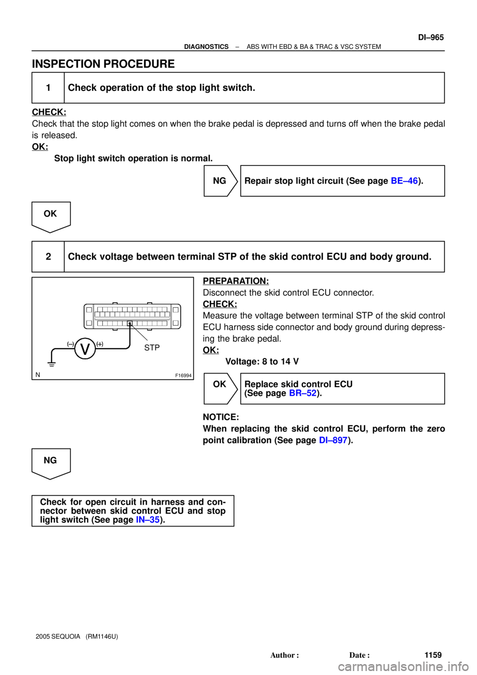
2 Check voltage between terminal STP of the skid control ECU and body ground.
PREPARATION:
Disconnect the skid control ECU connector.
CHECK:
Measure the voltage between terminal STP of the skid control
ECU harness side connector and body ground during depress-
ing the brake pedal.
OK:
Voltage: 8 to 14 V
OK Replace skid control ECU
(See page BR±52).
NOTICE:
When replacing the skid control ECU, perform the zero
point calibration (See page DI±897).
NG
Check for open circuit in harness and con-
nector between skid control ECU and stop
light switch (See page IN±35).
Page 1168 of 4323
F19782
Battery16
S1+BS
GND1
GND2
+BM S1
S1 S1 47
1
32 B±R
B±R
W±B
W±B W±B W±B 5 BF10
Fusible Link BlockABS & VSC Actuator
(Skid Control ECU)
IG J18
J/C
A A3
ABS
Motor Relay
Pump
Motor IL117
IL19 DI±966
± DIAGNOSTICSABS WITH EBD & BA & TRAC & VSC SYSTEM
1160 Author�: Date�:
2005 SEQUOIA (RM1146U)
DTC C1251 / 51 Pump Motor is Locked/
Open Circuit in Pump Motor Circuit
CIRCUIT DESCRIPTION
ABS pump motor is located inside the brake actuator.
The motor is used for BA, TRAC and VSC operation.
DTC No.DTC Detecting ConditionTrouble Area
C1251 / 51Pump motor does not operate during the initial check.ABS & VSC actuator
WIRING DIAGRAM
DIDMC±01
Page 1169 of 4323
± DIAGNOSTICSABS WITH EBD & BA & TRAC & VSC SYSTEM
DI±967
1161 Author�: Date�:
2005 SEQUOIA (RM1146U)
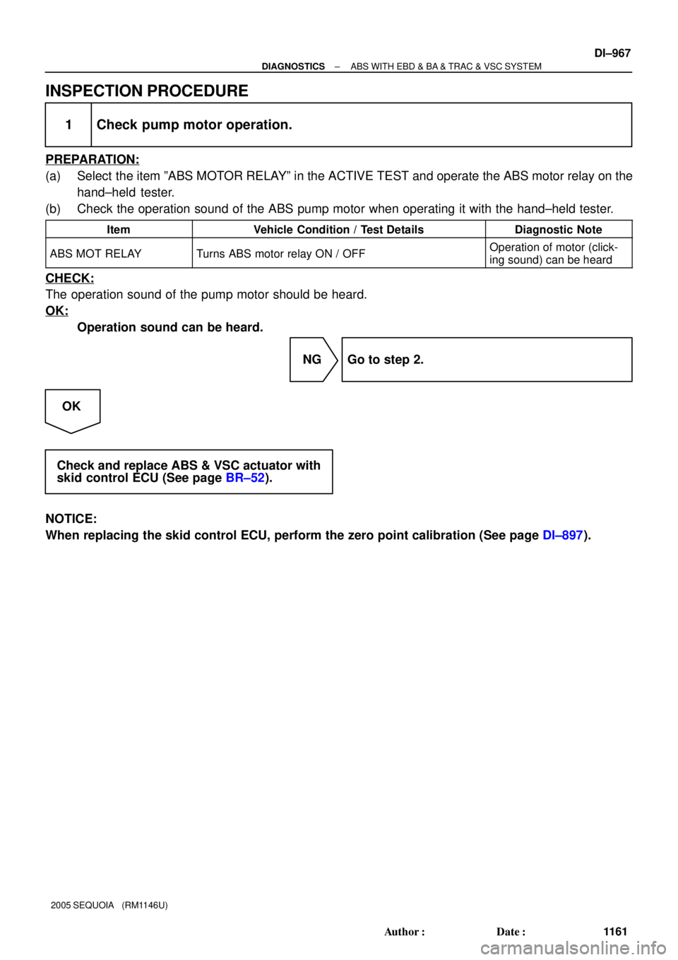
INSPECTION PROCEDURE
1 Check pump motor operation.
PREPARATION:
(a) Select the item ºABS MOTOR RELAYº in the ACTIVE TEST and operate the ABS motor relay on the
hand±held tester.
(b) Check the operation sound of the ABS pump motor when operating it with the hand±held tester.
ItemVehicle Condition / Test DetailsDiagnostic Note
ABS MOT RELAYTurns ABS motor relay ON / OFFOperation of motor (click-
ing sound) can be heard
CHECK:
The operation sound of the pump motor should be heard.
OK:
Operation sound can be heard.
NG Go to step 2.
OK
Check and replace ABS & VSC actuator with
skid control ECU (See page BR±52).
NOTICE:
When replacing the skid control ECU, perform the zero point calibration (See page DI±897).
Page 1170 of 4323
F16991
GND
DI±968
± DIAGNOSTICSABS WITH EBD & BA & TRAC & VSC SYSTEM
1162 Author�: Date�:
2005 SEQUOIA (RM1146U)
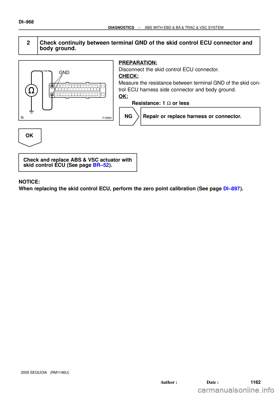
2 Check continuity between terminal GND of the skid control ECU connector and
body ground.
PREPARATION:
Disconnect the skid control ECU connector.
CHECK:
Measure the resistance between terminal GND of the skid con-
trol ECU harness side connector and body ground.
OK:
Resistance: 1 W or less
NG Repair or replace harness or connector.
OK
Check and replace ABS & VSC actuator with
skid control ECU (See page BR±52).
NOTICE:
When replacing the skid control ECU, perform the zero point calibration (See page DI±897).
Page 1171 of 4323
F14399F16956
BSTP
BST 3S1 31
17 4 A9
Active Brake BoosterABS &VSC Actuator
(Skid Control ECU)
BSTP
BSTS1 G±B
LG±B
± DIAGNOSTICSABS WITH EBD & BA & TRAC & VSC SYSTEM
DI±969
1163 Author�: Date�:
2005 SEQUOIA (RM1146U)
DTC C1310 / 11 Open or Short Circuit in Active Brake
Booster Solenoid Circuit
CIRCUIT DESCRIPTION
Operates when booster's negative pressure is insufficient and allows for a stable braking control.
DTC No.DTC Detecting ConditionTrouble Area
C1310 / 11Open or short in active brake booster solenoid circuit.�Brake booster
�Active brake booster solenoid circuit
WIRING DIAGRAM
DI93R±04
Page 1172 of 4323
F13988
34
DI±970
± DIAGNOSTICSABS WITH EBD & BA & TRAC & VSC SYSTEM
1164 Author�: Date�:
2005 SEQUOIA (RM1146U)
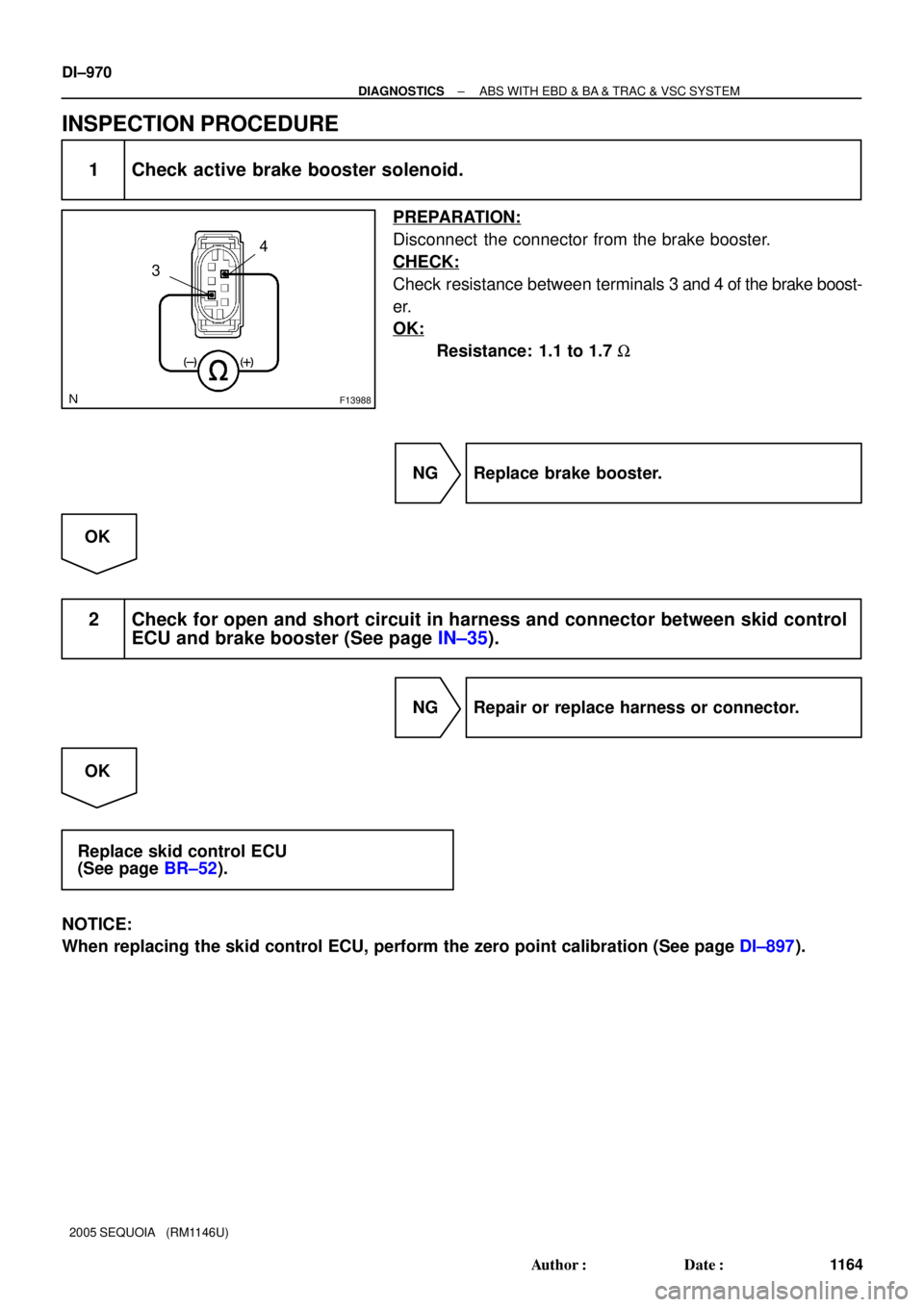
INSPECTION PROCEDURE
1 Check active brake booster solenoid.
PREPARATION:
Disconnect the connector from the brake booster.
CHECK:
Check resistance between terminals 3 and 4 of the brake boost-
er.
OK:
Resistance: 1.1 to 1.7 W
NG Replace brake booster.
OK
2 Check for open and short circuit in harness and connector between skid control
ECU and brake booster (See page IN±35).
NG Repair or replace harness or connector.
OK
Replace skid control ECU
(See page BR±52).
NOTICE:
When replacing the skid control ECU, perform the zero point calibration (See page DI±897).
Page 1173 of 4323
± DIAGNOSTICSABS WITH EBD & BA & TRAC & VSC SYSTEM
DI±971
1165 Author�: Date�:
2005 SEQUOIA (RM1146U)
DTC C1311 / 12 Open or Short Circuit in Brake Inhibit
Relay Circuit
CIRCUIT DESCRIPTION
Built in the stop lamp circuit and prohibits the stop lamp from turning on under VSC control.
DTC No.DTC Detecting ConditionTrouble Area
C1311 / 12Open or short circuit is detected.�Brake inhibit relay
�Brake inhibit relay circuit
DI93S±03

G±Y S14
Stop Light SW
I18 Ignition SW1 4 W
W±L
IG1
AM12
1
B±Y Instrument Panel J/B
2 1
1L
1F
1F1C
1C 1
2
46 STOP
AM1
ECU±IG W
4
B±R
Sub J/B No.3
3C8")

IG J18
J/C
A A3
ABS
Motor Relay
Pump
Motor IL117
IL19")