Page 1206 of 4323
DI±1004
± DIAGNOSTICSABS WITH EBD & BA & TRAC & VSC SYSTEM
1198 Author�: Date�:
2005 SEQUOIA (RM1146U)
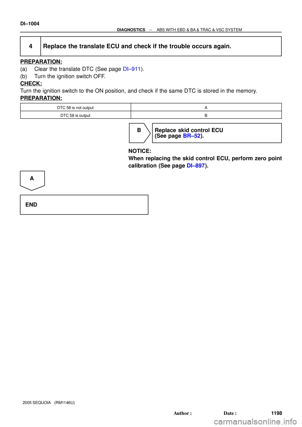
4 Replace the translate ECU and check if the trouble occurs again.
PREPARATION:
(a) Clear the translate DTC (See page DI±911).
(b) Turn the ignition switch OFF.
CHECK:
Turn the ignition switch to the ON position, and check if the same DTC is stored in the memory.
PREPARATION:
DTC 58 is not outputA
DTC 58 is outputB
B Replace skid control ECU
(See page BR±52).
NOTICE:
When replacing the skid control ECU, perform zero point
calibration (See page DI±897).
A
END
Page 1207 of 4323

DTC 65 Malfunction 1 of Vehicle CAN
CIRCUIT DESCRIPTION
The circuit is used to send TRAC&VSC")
± DIAGNOSTICSABS WITH EBD & BA & TRAC & VSC SYSTEM
DI±1005
1199 Author�: Date�:
2005 SEQUOIA (RM1146U)
DTC 65 Malfunction 1 of Vehicle CAN
CIRCUIT DESCRIPTION
The circuit is used to send TRAC&VSC control information from the skid control ECU to the ECM, and engine
control information from the ECM to the skid control ECU via the CAN communication system.
This DTC is output when communication between the translate ECU and the skid control ECU is cut off.
DTC No.DTC Detecting ConditionTrouble Area
65
Any of the following 1. through 3. is detected when IG1
voltage is 8.5 V or more and vehicle speed exceeds by 9
mph (15 km/h) or more.
1. Condition that signal cannot be received from ECM at
least once within 5 sec. occurs 10 times or more within
60 seconds.
2. Signal cannot be received continuously for 2 sec. or
more.
3. Condition that signal cannot be sent to ECM at least
once within 5 sec. occurs 10 times or more within 60
seconds.
�ENG+, ENG± circuit (CAN communication system)
�ECM
�Translate ECU
�Suspension control ECU
DIDMJ±01
Page 1208 of 4323
F19799
S25
Suspension Control ECU
CANL
CANH34
33W
L2
J53
12
J55
1
J55W
R16
T5
14
T5ENG±
ENG+
VSC+
VSC± 7
T5
11
T5 L
W
WL7
IL2
6
IL2 26 S1 ABS & VSC Actuator
(Skid Control ECU)Translate
ECU
IG1 1
T5 B±R
J37 J37J/C Sub J/B No.3
8
3C 8
3AB±R B±R
B±Y
W±L I18
Ignition SW
WInstrument Panel J/B
4
1F
1
1L4
1C
6
1C ECU±IG
AM1
AM1 IG1
ALT
BatteryGND 40
T5 J43
J/C
O
A A O
IG1
2 CANH
CANL
AA
8
5
BF10
Fusible Link
Block
J53J56 J5612 W
G 28
29 CANL
CANH
E5
ECM
(*1) Vehicle CAN Circuit
(*2) CAN1 Circuit (*1)
(*2)(*1)
(*1)
(*1)(*1)
(*1)
(*2)(*2)
(*2) DI±1006
± DIAGNOSTICSABS WITH EBD & BA & TRAC & VSC SYSTEM
1200 Author�: Date�:
2005 SEQUOIA (RM1146U)
WIRING DIAGRAM
Page 1209 of 4323
F19152
Translate ECU
GND
± DIAGNOSTICSABS WITH EBD & BA & TRAC & VSC SYSTEM
DI±1007
1201 Author�: Date�:
2005 SEQUOIA (RM1146U)
INSPECTION PROCEDURE
1 Check DTC of the VSC (See page DI±911).
CHECK:
Check skid control ECU DTC.
RESULT:
DTC is not outputA
DTC is outputB
B Repair circuit indicated by the output code
(See page DI±921).
A
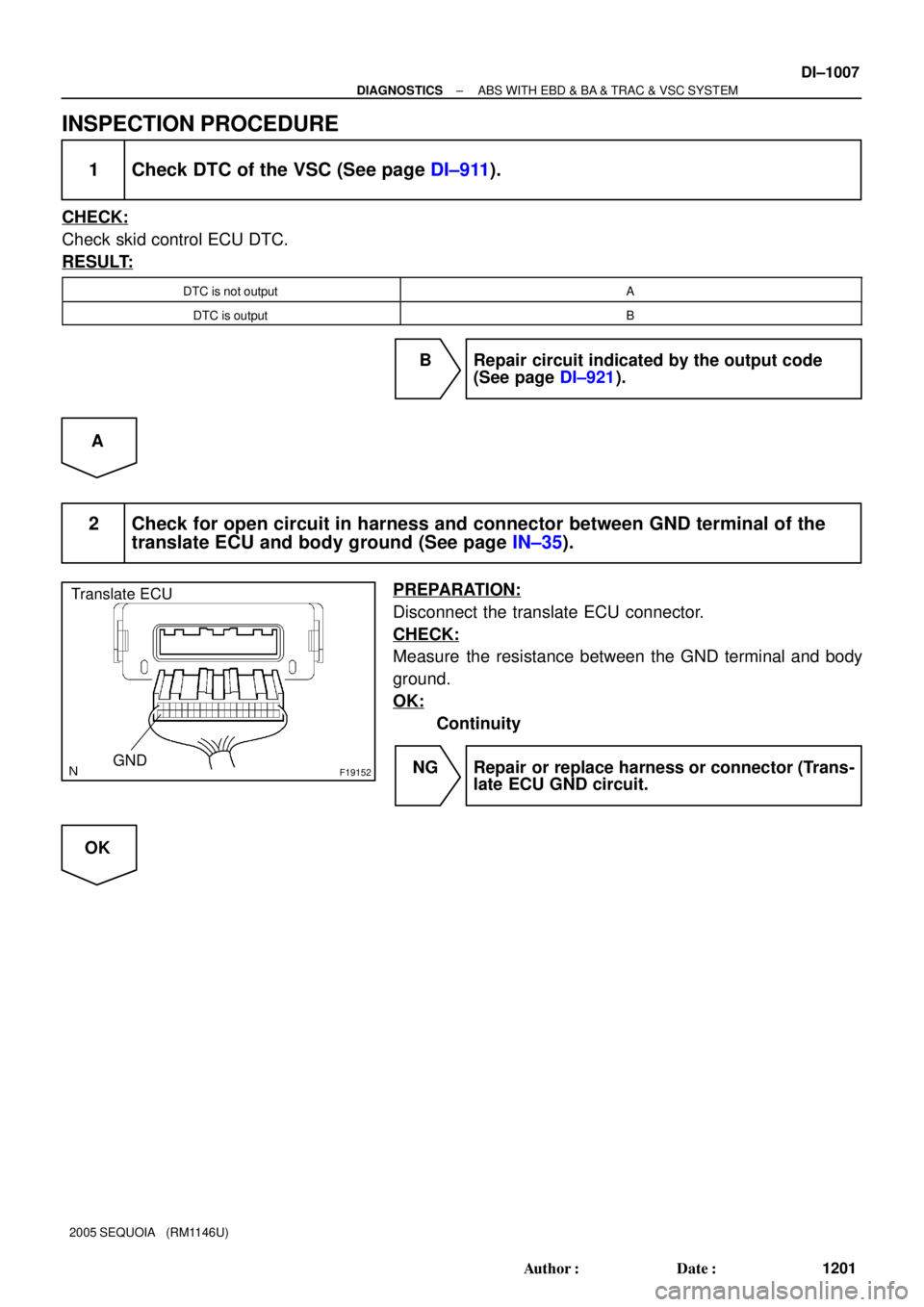
2 Check for open circuit in harness and connector between GND terminal of the
translate ECU and body ground (See page IN±35).
PREPARATION:
Disconnect the translate ECU connector.
CHECK:
Measure the resistance between the GND terminal and body
ground.
OK:
Continuity
NG Repair or replace harness or connector (Trans-
late ECU GND circuit.
OK
Page 1210 of 4323
DI±1008
± DIAGNOSTICSABS WITH EBD & BA & TRAC & VSC SYSTEM
1202 Author�: Date�:
2005 SEQUOIA (RM1146U)
3 Replace the translate ECU and check if the trouble occurs again.
PREPARATION:
(a) Clear the translate DTC (See page DI±911).
(b) Turn the ignition switch OFF.
CHECK:
Turn the ignition switch to the ON position, and check if the same DTC is stored in the memory.
PREPARATION:
DTC 65 is not outputA
DTC 65 is outputB
B Check and replace suspension control ECU,
ECM or CAN communication system.
A
END
Page 1211 of 4323
± DIAGNOSTICSABS WITH EBD & BA & TRAC & VSC SYSTEM
DI±1009
1203 Author�: Date�:
2005 SEQUOIA (RM1146U)
DTC 94 Malfunction 2 of Vehicle CAN
CIRCUIT DESCRIPTION
The circuit is used to send TRAC&VSC control information from the skid control ECU to the ECM, and engine
control information from the ECM to the skid control ECU via CAN communication system.
This DTC is output when the ECM and translate ECU cannot communicate with each other.
DTC No.DTC Detecting ConditionTrouble Area
94
When each of the following 1 or 2 is detected at IG1 voltage
of 8.5 V or more.
1. Communication error because of noise.
2. Data sending error after writing to output device for 5
sec. or more.�ENG+, ENG± circuit (CAN communication system)
�ECM
�Translate ECU
�Suspension control ECU
DIDMK±01
Page 1212 of 4323
F19799
S25
Suspension Control ECU
CANL
CANH34
33W
L2
J53
12
J55
1
J55W
R16
T5
14
T5ENG±
ENG+
VSC+
VSC± 7
T5
11
T5 L
W
WL7
IL2
6
IL2 26 S1 ABS & VSC Actuator
(Skid Control ECU)Translate
ECU
IG1 1
T5 B±R
J37 J37J/C Sub J/B No.3
8
3C 8
3AB±R B±R
B±Y
W±L I18
Ignition SW
WInstrument Panel J/B
4
1F
1
1L4
1C
6
1C ECU±IG
AM1
AM1 IG1
ALT
BatteryGND 40
T5 J43
J/C
O
A A O
IG1
2 CANH
CANL
AA
8
5
BF10
Fusible Link
Block
J53J56 J5612 W
G 28
29 CANL
CANH
E5
ECM
(*1) Vehicle CAN Circuit
(*2) CAN1 Circuit (*1)
(*2)(*1)
(*1)
(*1)(*1)
(*1)
(*2)(*2)
(*2) DI±1010
± DIAGNOSTICSABS WITH EBD & BA & TRAC & VSC SYSTEM
1204 Author�: Date�:
2005 SEQUOIA (RM1146U)
WIRING DIAGRAM
Page 1213 of 4323
F19152
Translate ECU
GND
± DIAGNOSTICSABS WITH EBD & BA & TRAC & VSC SYSTEM
DI±1011
1205 Author�: Date�:
2005 SEQUOIA (RM1146U)
INSPECTION PROCEDURE
1 Check DTC of the VSC (See page DI±911)
CHECK:
Check skid control ECU DTC.
RESULT:
DTC is not outputA
DTC is outputB
B Repair circuit indicated by the output code
(See page DI±921).
A
2 Check for open circuit in harness and connector between GND terminal of the
translate ECU and body ground (See page IN±35).
PREPARATION:
Disconnect the translate ECU connector.
CHECK:
Measure the resistance between the GND terminal and body
ground.
OK:
Continuity
NG Repair or replace harness or connector (Trans-
late ECU GND circuit).
OK
Translate
ECU
IG1 1
T5")


Translate
ECU
IG1 1
T5")
