Page 1214 of 4323
DI±1012
± DIAGNOSTICSABS WITH EBD & BA & TRAC & VSC SYSTEM
1206 Author�: Date�:
2005 SEQUOIA (RM1146U)
3 Replace the translate ECU and check if the trouble occurs again.
PREPARATION:
(a) Clear the translate DTC (See page DI±911).
(b) Turn the ignition switch OFF.
CHECK:
Turn the ignition switch to the ON position, and check if the same DTC is stored in the memory.
PREPARATION:
DTC 94 is not outputA
DTC 94 is outputB
B Check and repair suspension control ECU, ECM
or CAN communication system.
A
END
Page 1215 of 4323

DTC Normal Code Malfunction in Translate ECU
CIRCUIT DESCRIPTION
If any trouble occurs in the")
± DIAGNOSTICSABS WITH EBD & BA & TRAC & VSC SYSTEM
DI±1013
1207 Author�: Date�:
2005 SEQUOIA (RM1146U)
DTC Normal Code Malfunction in Translate ECU
CIRCUIT DESCRIPTION
If any trouble occurs in the engine control system, the skid control ECU prohibits ABS & VSC control.
DTC No.DTC Detecting ConditionTrouble Area
Normal Code
Conditions 1., 2. or 3. continue for 5 sec. or more:
1. Engine malfunction signal is sent from ECM.
2. Shift malfunction signal is sent from ECM.
3. The shift position is other than P and N, and P range
input voltage is 8 V or more.
�ECM circuit
�ECM
�Brake fluid level
�Brake fluid level warning switch circuit
�Steering angle sensor
�Translate ECU
�Skid control ECU
�Vehicle CAN
�VSC+, VSC± circuit (CAN1 communication system)
INSPECTION PROCEDURE
1 Is DTC output for ECM?
Check DTC on page DI±43.
YES Repair engine control system according to the
output code (See page DI±58).
NO
2 Check the DTC of the ABS and VSC (See page DI±911).
CHECK:
Check skid control ECU DTC.
RESULT:
Only DTC ºC1203/53º of the VSC system is outputA
Except DTC ºC1203/53º of the VSC system are outputB
B Repair ABS and VSC control system according
to the code output (See page DI±921).
A
DI6OF±12
Page 1216 of 4323
DI±1014
± DIAGNOSTICSABS WITH EBD & BA & TRAC & VSC SYSTEM
1208 Author�: Date�:
2005 SEQUOIA (RM1146U)
3 Replace the translate ECU and check if the trouble occurs again.
PREPARATION:
(a) Clear the DTC (See page DI±911).
(b) Turn the ignition switch OFF.
CHECK:
Turn the ignition switch to the ON position, and check if the same DTC is stored in the memory.
PREPARATION:
DTC is not outputA
DTC is outputB
B Replace skid control ECU
(See page BR±52).
NOTICE:
When replacing the skid control ECU, perform zero point
calibration (See page DI±897).
A
END
Page 1217 of 4323
± DIAGNOSTICSABS WITH EBD & BA & TRAC & VSC SYSTEM
DI±1015
1209 Author�: Date�:
2005 SEQUOIA (RM1146U)
DTC Non ± Code Translate ECU malfunction
CIRCUIT DESCRIPTION
Translate ECU DTCs can be read by blinks of the brake warning light (see page DI±911).
DTC No.DTC Detecting ConditionTrouble Area
Non ± code*Translate ECU internal malfunction is detected.
�Brake warning light circuit
�Tc terminal circuit
�Translate ECU
*: Neither the normal system code nor a trouble code is output.
INSPECTION PROCEDURE
1 Check the BRAKE warning light circuit (See page DI±1033).
OK:
BRAKE warning light circuit is normal.
NG Repair or replace the BRAKE warning light cir-
cuit.
OK
2 Check the Tc terminal circuit (See page DI±1055).
OK:
Tc terminal circuit is normal.
NG Repair or replace the Tc terminal circuit.
OK
Check and replace the translate ECU.
DI942±03
Page 1218 of 4323
DI±1016
± DIAGNOSTICSABS WITH EBD & BA & TRAC & VSC SYSTEM
1210 Author�: Date�:
2005 SEQUOIA (RM1146U)
DTC Always ON* Malfunction in Skid Control ECU
*: ABS warning light
When reading DTCs by SST (CHECK WIRE), if the ABS warning light remains ON, troubleshoot by following
the inspection flow.
CIRCUIT DESCRIPTION
DTC No.DTC Detecting ConditionTrouble Area
Always ON
When any of the following conditions are detected:
1. Malfunction in ECU internal circuit is identified.
2. ECU power source voltage is too high.
�Battery
�Charging system
�Power source circuit
�ABS warning light circuit
�Skid control ECU
HINT:
There is a possibility that the hand±held tester cannot be used when the ECU is abnormal.
DI943±03
Page 1219 of 4323
F19777
ABS & VSC Actuator
(Skid Control ECU)
WA 35
S1 R±W IL2 4 R±W
21 C6
Combination Meter
Instrument Panel J/B
11
1HB±O
24
2 1CIGN1
B±R
I18
Ignition SW
IG2
AM2
IG1
AM13
1C
6
1C
4
1C7
1J
1
1L
4
1F AM1
ECU±IG1 2
2 6
5
1W±R
W±L
B±YW±R
WBB 1
2C1
2D
B±RSub J/B No.3
8
3A8
3CB±R
B±R
B±R B±R
W±B A
J37
A
J38 A
J371
IL113
S1
IG1 IG1
GND1
40O
O A
AA
AW±B
W±B
W±B J18
J/C J43
J/C17
IL1
9
IL11
S1
GND1
GND2 32
S1
IG IG W
B
B 5 8
4
ALTF10
Fusible
Link
Block
BatteryEngine Room J/B
AM2
J/C T5
Translate ECUABS
B±R
± DIAGNOSTICSABS WITH EBD & BA & TRAC & VSC SYSTEM
DI±1017
1211 Author�: Date�:
2005 SEQUOIA (RM1146U)
WIRING DIAGRAM
Page 1220 of 4323
F16990
ON
IG1
GND
DI±1018
± DIAGNOSTICSABS WITH EBD & BA & TRAC & VSC SYSTEM
1212 Author�: Date�:
2005 SEQUOIA (RM1146U)
INSPECTION PROCEDURE
1 Is DTC output?
Check DTC on page DI±911.
YES Repair circuit indicated by the output code
(See page DI±921).
NO
2 Check that the skid control ECU connector is securely connected to the skid
control ECU (See page IN±35).
NG Connect the connector to the skid control ECU.
OK
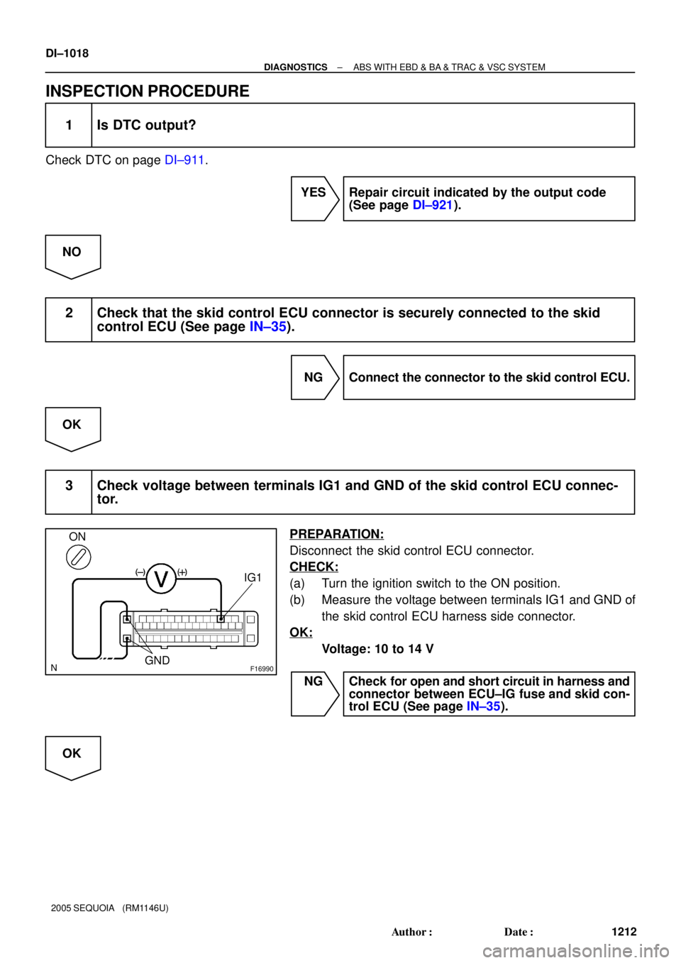
3 Check voltage between terminals IG1 and GND of the skid control ECU connec-
tor.
PREPARATION:
Disconnect the skid control ECU connector.
CHECK:
(a) Turn the ignition switch to the ON position.
(b) Measure the voltage between terminals IG1 and GND of
the skid control ECU harness side connector.
OK:
Voltage: 10 to 14 V
NG Check for open and short circuit in harness and
connector between ECU±IG fuse and skid con-
trol ECU (See page IN±35).
OK
Page 1221 of 4323
± DIAGNOSTICSABS WITH EBD & BA & TRAC & VSC SYSTEM
DI±1019
1213 Author�: Date�:
2005 SEQUOIA (RM1146U)
4 Check battery positive voltage.
CHECK:
Check the battery positive voltage.
OK:
Voltage: 10 to 14 V
NG Check and repair the charging system
(See page CH±1).
OK
5 Check the Tc terminal circuit (See page DI±1055).
OK:
Tc terminal circuit is normal
NG Repair or replace the Tc terminal circuit.
OK


WA 35
S1 R±W IL2 4 R±W
21 C6
Combination Meter
Instrument Panel J/B
11
1HB±O
24
2 1CIGN1
B±R
I18
Ignition SW
IG2
AM2
IG1
AM13
1C
6
1C
4
1C7
1J
1
1L")