Page 1230 of 4323
F19778
ABS & VSC Actuator
(Skid Control ECU)
VSCW 44
S1 P±L IL2 3 P±L
3 C6
Combination SW Instrument Panel J/B
11
1HB±O
24
2 1CIGN1
B±R
I18
Ignition SW
IG2 AM2
IG1
AM13
1C
6
1C
4
1C7
1J
1
1L
4
1F AM1
ECU±IG1 2
265
1W±R
W±L
B±YW±R
WBB 1
2C1
2D
B±RSub J/B No.3
8
3A8
3CB±R
B±R
B±R B±R
W±B A
J37
A
J38 A
J371
IL113
S1
IG1 IG1
GND1
40O
O A
AA
AW±B
W±B W±B
J18
J/C J43
J/C17
IL1
9
IL11
S1 GND1
GND2 32
S1
IG
IG W
B
B 5 8
4
ALTF10
Fusible
Link
Block
BatteryEngine Room J/B
AM2
J/C T5
Translate ECUVSC TRAC
7
11L
WB±R
L
W 7
IL26
S1
6
IL22
S1CANH
CANL VSC+
VSC±
(*) CAN1 Circuit (*) (*)
(*)
(*) DI±1028
± DIAGNOSTICSABS WITH EBD & BA & TRAC & VSC SYSTEM
1222 Author�: Date�:
2005 SEQUOIA (RM1146U)
WIRING DIAGRAM
Page 1231 of 4323

INSPECTION PROCEDURE
HINT:
Start the inspection from step 1 when using the hand±held tester")
± DIAGNOSTICSABS WITH EBD & BA & TRAC & VSC SYSTEM
DI±1029
1223 Author�: Date�:
2005 SEQUOIA (RM1146U)
INSPECTION PROCEDURE
HINT:
Start the inspection from step 1 when using the hand±held tester and start from step 2 when not using the
hand±held tester.
1 Check operation of the VSC warning light.
PREPARATION:
(a) Connect the hand±held tester to the DLC3.
(b) Turn the ignition switch to the ON position and push the hand±held tester main switch ON.
(c) Select ACTIVE TEST mode on the hand±held tester.
CHECK:
Check that ºONº and ºOFFº of the VSC TRAC warning light can be shown on the combination meter with
the hand±held tester.
ItemVehicle Condition / Test DetailsDiagnostic Note
VSC / TRC OFF INDTurns VSC / TRAC OFF indicator ON / OFFObserve combination me-
ter
OK:
VSC TRAC warning light operates.
OK Go to step 5.
NG
2 Is DTC output?
Check DTC on page DI±911.
YES Repair circuit indicated by the output code
(See page DI±921).
NO
3 Check for open and short circuit in harness and connector between skid control
ECU and VSC TRAC warning light (See page IN±35).
NG Repair or replace harness or connector.
OK
Page 1232 of 4323
DI±1030
± DIAGNOSTICSABS WITH EBD & BA & TRAC & VSC SYSTEM
1224 Author�: Date�:
2005 SEQUOIA (RM1146U)
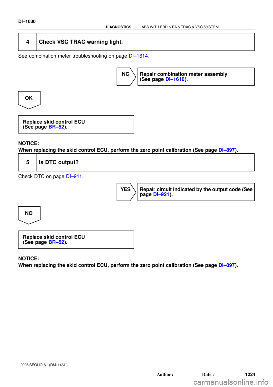
4 Check VSC TRAC warning light.
See combination meter troubleshooting on page DI±1614.
NG Repair combination meter assembly
(See page DI±1610).
OK
Replace skid control ECU
(See page BR±52).
NOTICE:
When replacing the skid control ECU, perform the zero point calibration (See page DI±897).
5 Is DTC output?
Check DTC on page DI±911.
YES Repair circuit indicated by the output code (See
page DI±921).
NO
Replace skid control ECU
(See page BR±52).
NOTICE:
When replacing the skid control ECU, perform the zero point calibration (See page DI±897).
Page 1233 of 4323

VSC TRAC Warning Light Circuit (Does not light up)
CIRCUIT DESCRIPTION
See page DI±1027.
WIR")
± DIAGNOSTICSABS WITH EBD & BA & TRAC & VSC SYSTEM
DI±1031
1225 Author�: Date�:
2005 SEQUOIA (RM1146U)
VSC TRAC Warning Light Circuit (Does not light up)
CIRCUIT DESCRIPTION
See page DI±1027.
WIRING DIAGRAM
See page DI±1027.
INSPECTION PROCEDURE
HINT:
Start the inspection from step 1 when using the hand±held tester and start from step 2 when not using the
hand±held tester.
1 Check operation of the VSC warning light.
PREPARATION:
(a) Connect the hand±held tester to the DLC3.
(b) Turn the ignition switch to the ON position and push the hand±held tester main switch ON.
(c) Select ACTIVE TEST mode on the hand±held tester.
CHECK:
Check that ºONº and ºOFFº of the VSC TRAC warning light can be shown on the combination meter with
the hand±held tester.
ItemVehicle Condition / Test DetailsDiagnostic Note
VSC / TRC OFF INDTurns VSC / TRAC OFF indicator ON / OFFObserve combination me-
ter
OK:
VSC TRAC warning light operates.
NG Go to step 2.
OK
Replace skid control ECU
(See page BR±52).
NOTICE:
When replacing the skid control ECU, perform the zero point calibration (See page DI±897).
DIDMM±01
Page 1234 of 4323
DI±1032
± DIAGNOSTICSABS WITH EBD & BA & TRAC & VSC SYSTEM
1226 Author�: Date�:
2005 SEQUOIA (RM1146U)
2 Check for open and short circuit in harness and connector between skid control
ECU and VSC TRAC warning light (See page IN±35).
NG Repair or replace harness or connector.
OK
3 Check VSC TRAC warning light.
See combination meter troubleshooting on page DI±1614.
NG Repair combination meter assembly
(See page DI±1610).
OK
Replace skid control ECU
(See page BR±52).
NOTICE:
When replacing the skid control ECU, perform the zero point calibration (See page DI±897).
Page 1235 of 4323
± DIAGNOSTICSABS WITH EBD & BA & TRAC & VSC SYSTEM
DI±1033
1227 Author�: Date�:
2005 SEQUOIA (RM1146U)
BRAKE Warning Light Circuit (Remains ON)
CIRCUIT DESCRIPTION
The BRAKE warning light comes on when the brake fluid is insufficient, the parking brake is applied or the
EBD is defective.
The skid control ECU is connected to the translate ECU via the CAN1 communication system.
DIDMN±01
Page 1236 of 4323
F19769
Translate ECU
VSC+
VSC±
IG17
T5
T511
1
T5B±RL
W
AA
J37
J38
A
J37B±R J/C
B±R B±RL
W 7
IL2
6
IL2
1
IL16
S1
2
S1
13
S1 ABS &VSC Actuator
(Skid Control ECU)
CANH
CANL
IG1
8
3C8
3A
B±R Instrument Panel J/B
4
1C
2
1C
3
1C
6
1C4
1F
11
1H
7
1J
1
1L ECU±IG
IGN1
AM1 B±R B±Y
W±R
W±LB±O
W±R
W
1 2Combination Meter
24
C6
Brake
1C5 W
8
ALTF10 Fusible
Link BlockEngine Room J/B
A W±R 1
2D1
2C
4
5
R±B R±B
B1 Brake Fluid Level
Warning SW
Y±L Y±LW±B 23
IA1
129
IA5O
A
A O
OJ43
J/C
IG Sub J/B No.4
LG±R
LG±R 4
4B4
4D
1P2 Parking
Brake SW
B
Battery 39
T5
24
T5
40
T5
4
T5 BRL
LVL2
GND
PKB2Sub J/B No.3
I18
Ignition SW
AM1 IG1
AM2 IG2 1
5 W±L
2
6
AM2
BB±R (*) CAN1 Circuit
(*)
(*)
(*) (*) DI±1034
± DIAGNOSTICSABS WITH EBD & BA & TRAC & VSC SYSTEM
1228 Author�: Date�:
2005 SEQUOIA (RM1146U)
WIRING DIAGRAM
Page 1237 of 4323

INSPECTION PROCEDURE
HINT:
Start the inspection f")
F18068
Parking Brake Switch
Release Push
P2
± DIAGNOSTICSABS WITH EBD & BA & TRAC & VSC SYSTEM
DI±1035
1229 Author�: Date�:
2005 SEQUOIA (RM1146U)
INSPECTION PROCEDURE
HINT:
Start the inspection from step 1 when using the hand±held tester and start from step 2 when not using the
hand±held tester.
1 Check operation of the BRAKE warning light.
PREPARATION:
(a) Connect the hand±held tester to the DLC3.
(b) Turn the ignition switch to the ON position and hand±held tester main switch ON.
(c) Select the ACTIVE TEST mode on the hand±held.
CHECK:
Check that ºONº and ºOFFº of the BRAKE warning light can be shown on the combination meter with the
hand±held tester.
ItemVehicle Condition/Test DetailsDiagnostic Note
BRAKE WARN LIGHTTurn BRAKE warning light ON/OFFObserve combination meter
OK:
BRAKE warning light operates.
NG Go to step 6.
OK
2 Check parking brake switch assembly.
PREPARATION:
Disconnect the parking brake switch connector.
CHECK:
Measure the resistance according to the value(s) in the table
below.
OK:
Tester ConnectionSwitch ConditionSpecified Condition
P2±1 ± Ground partReleased1 W or less
P2±1 ± Ground partPushed in10 kW or more
NG Replace parking brake switch.
OK

VSCW 44
S1 P±L IL2 3 P±L
3 C6
Combination SW Instrument Panel J/B
11
1HB±O
24
2 1CIGN1
B±R
I18
Ignition SW
IG2 AM2
IG1
AM13
1C
6
1C
4
1C7
1J
1
1L
4")


CANH
CANL
IG1
8
3C8
3A
B±R Instrum")