Page 3816 of 4323
I11143
AC3HN±02
N16762
21
± AIR CONDITIONINGBLOWER MOTOR
AC±81
3808 Author�: Date�:
2005 SEQUOIA (RM1146U)
BLOWER MOTOR
INSPECTION
1. REMOVE BLOWER MOTOR
(a) Disconnect the connector.
(b) Remove the 3 screws and motor.
2. INSPECT BLOWER MOTOR OPERATION
Connect the positive (+) lead from the battery to terminal 1 and
the negative (±) lead to terminal 2, then check that the motor op-
erates smoothly.
If operation is not as specified, replace the blower motor.
3. INSTALL BLOWER MOTOR
(a) Install the motor with the 3 screws.
(b) Connect the connector.
Page 3817 of 4323
AC3HO±02
I21378
I22633
2
1
AC±82
± AIR CONDITIONINGREAR BLOWER MOTOR
3809 Author�: Date�:
2005 SEQUOIA (RM1146U)
REAR BLOWER MOTOR
INSPECTION
1. REMOVE REAR SEAT OUTER BELT FLOOR AN-
CHORS
2. REMOVE BACK DOOR SCUFF PLATE
3. REMOVE REAR DOOR SCUFF PLATE RH
4. REMOVE REAR WINDOW SIDE GARNISH
5. REMOVE REAR QUARTER TRIM PANEL RH
6. REMOVE BLOWER MOTOR
(a) Disconnect the blower motor connector.
(b) Remove the 3 screws and blower motor.
7. INSPECT BLOWER MOTOR OPERATION
Connect the positive (+) lead from the battery to terminal 2 and
the negative (±) lead to terminal 1, then check that the motor op-
erates smoothly.
If operation is not as specified, replace the blower motor.
8. INSTALL BLOWER MOTOR
9. INSTALL REAR QUARTER TRIM PANEL RH
10. INSTALL REAR WINDOW SIDE GARNISH
11. INSTALL REAR DOOR SCUFF PLATE RH
12. INSTALL BACK DOOR SCUFF PLATE
13. INSTALL REAR SEAT OUTER BELT FLOOR AN-
CHORS
Page 3819 of 4323

3811 Author�: Date�:
2005 SEQUOIA (RM1146U)
POWER TRANSISTOR (for Rear
A/C)
INSPECTION
1. REMOVE RE")
AC3HQ±02
I21379
I22616
1 2
4
I17711
3
4 AC±84
± AIR CONDITIONINGPOWER TRANSISTOR (for Rear A/C)
3811 Author�: Date�:
2005 SEQUOIA (RM1146U)
POWER TRANSISTOR (for Rear
A/C)
INSPECTION
1. REMOVE REAR SEAT OUTER BELT FLOOR AN-
CHORS
2. REMOVE BACK DOOR SCUFF PLATE
3. REMOVE REAR DOOR SCUFF PLATE RH
4. REMOVE REAR WINDOW SIDE GARNISH
5. REMOVE REAR QUARTER TRIM PANEL RH
6. REMOVE REAR POWER TRANSISTOR
(a) Disconnect the connector.
(b) Remove the 2 screws and the rear power transistor.
7. INSPECT POWER TRANSISTOR OPERATION
(a) Connect the positive (+) lead to terminal 1 through a
12 V ± 3.4 W test bulb and the negative (±) lead to
terminal 4.
(b) Check the test bulb lights up when another positive (+)
lead is connected to terminal 2 through a 12 V ± 3.4 W test
bulb.
If operation is not as specified, replace the power transistor.
8. INSPECT POWER TRANSISTOR RESISTANCE
Measure the resistance between terminals 3 and 4.
Standard resistance: 2.0 to 2.4 kW
If resistance is not as specified, replace the power transistor.
9. INSTALL REAR POWER TRANSISTOR
10. INSTALL REAR QUARTER TRIM PANEL RH
11. INSTALL REAR WINDOW SIDE GARNISH
12. INSTALL REAR DOOR SCUFF PLATE RH
13. INSTALL BACK DOOR SCUFF PLATE
Page 3827 of 4323

3,140 kpa 196 kpa
(2.0 kgf/cm
2, 28psi)
OFF (No Continuity)(32.0 kgf/cm2, 455psi)
OFF (No Continuity)
I05079
ON (Co")
I21455
2
13
4
AC1LS±03
Z13470
Low pressure High pressure
side side
ON (Continuity)
3,140 kpa 196 kpa
(2.0 kgf/cm
2, 28psi)
OFF (No Continuity)(32.0 kgf/cm2, 455psi)
OFF (No Continuity)
I05079
ON (Continuity)
1,520 kpa
1,230 kpa
(12.5 kgf/cm
2, 178psi) OFF (No Continuity)
(15.5 kgf/cm
2, 220psi) Cooling Fan Control AC±92
± AIR CONDITIONINGPRESSURE SWITCH
3819 Author�: Date�:
2005 SEQUOIA (RM1146U)
PRESSURE SWITCH
ON±VEHICLE INSPECTION
1. SET MANIFOLD GAUGE SET (See page AC±18)
2. DISCONNECT CONNECTOR
3. RUN ENGINE AT APPROX. 2,000 rpm
4. SET BLOWER SPEED CONTROL SWITCH TO ºHIº
POSITION
5. SET TEMPERATURE CONTROL LEVER TO ºMAX.
COOLº POSITION
6. A/C SWITCH ON
7. INSPECT PRESSURE SWITCH OPERATION
(a) Connect the positive (+) lead from the ohmmeter to termi-
nal 4 and the negative (±) lead to terminal 1.
(b) Check continuity between terminals when refrigerant
pressure is changed, as shown in the illustration.
If operation is not as specified, replace the pressure switch.
8. Cooling fan control:
INSPECT PRESSURE SWITCH OPERATION
9. STOP ENGINE AND REMOVE MANIFOLD GAUGE
SET
10. CONNECT CONNECTOR TO PRESSURE SWITCH
(a) Connect the positive (+) lead from the ohmmeter to termi-
nal 2 and the negative (±) lead to terminal 3.
(b) Check continuity between terminals when refrigerant
pressure is changed, as shown in the illustration.
If operation is not as specified, replace the pressure switch.
11. STOP ENGINE AND REMOVE MANIFOLD GAUGE
SET
12. CONNECT CONNECTOR TO PRESSURE SWITCH
Page 3830 of 4323
I21427
Heater RelayCondenser
Fan Relay
Magnetic
Clutch Relay
Rear Heater Relay
AC3HU±02
N02832
1
2 3
5
1
23
5
4
4
Z18060
23
15
5
13
2
± AIR CONDITIONINGRELAY
AC±95
3822 Author�: Date�:
2005 SEQUOIA (RM1146U)
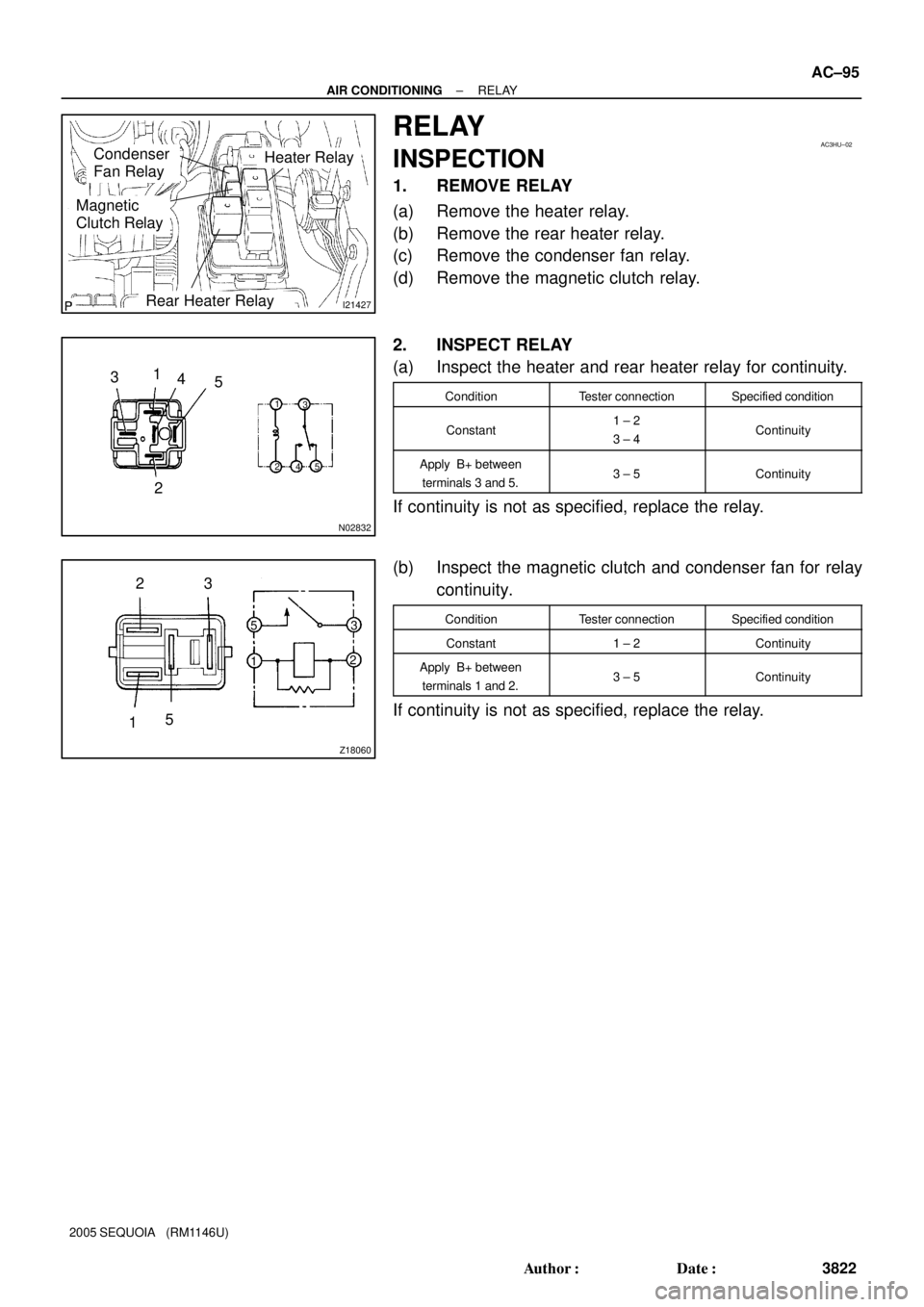
RELAY
INSPECTION
1. REMOVE RELAY
(a) Remove the heater relay.
(b) Remove the rear heater relay.
(c) Remove the condenser fan relay.
(d) Remove the magnetic clutch relay.
2. INSPECT RELAY
(a) Inspect the heater and rear heater relay for continuity.
ConditionTester connectionSpecified condition
Constant1 ± 2
3 ± 4Continuity
Apply B+ between
terminals 3 and 5.3 ± 5Continuity
If continuity is not as specified, replace the relay.
(b) Inspect the magnetic clutch and condenser fan for relay
continuity.
ConditionTester connectionSpecified condition
Constant1 ± 2Continuity
Apply B+ between
terminals 1 and 2.3 ± 5Continuity
If continuity is not as specified, replace the relay.
Page 3855 of 4323

vi
2005 SEQUOIA from Aug. 04 Prod. (OM34424U)
Important health and safety
information about your Toyota
CAUTION
�WARNING: Engine exhaust, some of its constitu-
ents, and a wid")
05_SEQUOIA_U (L/O 0408)
vi
2005 SEQUOIA from Aug. '04 Prod. (OM34424U)
Important health and safety
information about your Toyota
CAUTION
�WARNING: Engine exhaust, some of its constitu-
ents, and a wide variety of automobile compo-
nents contain or emit chemicals known to the
State of California to cause cancer and birth de-
fects and other reproductive harm. In addition,
oils, fuels and fluids contained in vehicles as
well as waste produced by component wear con-
tain or emit chemicals known to the State of
California to cause cancer and birth defects or
other reproductive harm.
�Battery posts, terminals and related accessories
contain lead and lead compounds. Wash your
hands after handling. Used engine oil contains
chemicals that have caused cancer in laboratory
animals. Always protect your skin by washing
thoroughly with soap and water.
Accessories, spare parts and
modification of your Toyota
A wide variety of non±genuine spare parts and accesso-
ries for Toyota vehicles are currently available in the
market. You should know that Toyota does not warrant
these products and is not responsible for their perfor-
mance, repair, or replacement, or for any damage they
may cause to, or adverse effect they may have on,
your Toyota vehicle.
This vehicle should not be modified with non±genuine
Toyota products. Modification with non±genuine Toyota
products could affect its performance, safety or durabili-
ty, and may even violate governmental regulations. In
addition, damage or performance problems resulting from
the modification may not be covered under warranty.
Page 3861 of 4323
05_SEQUOIA_U (L/O 0408)
2
2005 SEQUOIA from Aug. '04 Prod. (OM34424U)
1. Side vents
2. Instrument cluster
3. Center vents
4. Multi±information display
5. Personal lights
6. Garage door opener box or auxiliary
box
7. Electric moon roof switches
8. Side defroster outlet
9. Glove box
10. Power door lock switches
11. Power window switches
12. Power outlets
13. Seat heater switches
14. Rear console box
15. Rear air conditioning controls
16. Headphone input jacks and headphone
volume control dials
17. Input terminal adapter
18. Cup holders
19. Power rear view mirror control switches
20. Lower vent
Instrument panel overview
�View A
Page 3882 of 4323
05_SEQUOIA_U (L/O 0408)
23
2005 SEQUOIA from Aug. '04 Prod. (OM34424U)
For replacement, use a CR2016 lithium
battery or equivalent.
CAUTION
Special care should be taken to pre-
vent small children from swallowing
the removed battery or components.
NOTICE
�When replacing the battery, be care-
ful not to lose the components.
�Replace only with the same or
equivalent type recommended by a
Toyota dealer.
�Dispose of used batteries according
to the local laws.
Replace the battery by following these
procedures:
1. Using a coin or equivalent, open the
transmitter case.2. Remove the discharged transmitter bat-
tery by ballpoint pen. Insert the tip of
ballpoint pen at the guide groove and
lift as shown in the above illustration.
NOTICE
Do not bend the terminals.
ÐReplacing battery


2
2005 SEQUOIA from Aug. 04 Prod. (OM34424U)
1. Side vents
2. Instrument cluster
3. Center vents
4. Multi±information display
5. Personal lights
6. Garage door opener box or")

23
2005 SEQUOIA from Aug. 04 Prod. (OM34424U)
For replacement, use a CR2016 lithium
battery or equivalent.
CAUTION
Special care should be taken to pre-
vent small children fro")