Page 3558 of 4323
I01200
2 1
35
2 5
1 3
BE±146
± BODY ELECTRICALHORN SYSTEM
3550 Author�: Date�:
2005 SEQUOIA (RM1146U)
4. INSPECT HORN RELAY CONTINUITY
ConditionTester connectionSpecified condition
Always1 ± 2Continuity
Always3 ± 5No continuity
Apply B+ between
terminals 1 and 2.3 ± 5Continuity
If continuity is not as specified, replace the relay.
5. INSPECT HORN RELAY CIRCUIT
(See page DI±1764)
Page 3561 of 4323

I24379
Wire Harness Side:
I18635
1
2 34
5
I18635
1
2 34
5
± BODY ELECTRICALTRAILER TOWING
BE±149
3553 Author�: Date�:
2005 SEQUOIA (RM1146U)
2. Trailer Socket 7 Pin Type:
INSPECT BRAKE CONTROLLER CIRCUIT
Remove the brake controller with the connector still connected
and inspect the wire harness side connector from the back side,
as shown in the table below.
Tester connectionConditionSpecified condition
1 ± 3Stop light switch ON (Brake pedal depressed)10 ± 14 V
1 ± 3Stop light switch OFF (Brake pedal released)0 V
2 ± 3Always10 ± 14 V
3 ± 4Stop light switch ON (Brake pedal depressed)10 ± 14 V
3 ± 4Stop light switch OFF (Brake pedal released)0 V
3 ± 5Light control switch TAIL or HEAD10 ± 14 V
3 ± 5Light control switch OFF0 V
If the circuit is not as specified, inspect the circuit connected to
other parts.
3. INSPECT TOWING TAIL RELAY CONTINUITY
ConditionTester connectionSpecified condition
Always1 ± 2Continuity
Always3 ± 5No continuity
Apply B+ between
terminals 1 and 2.3 ± 5Continuity
If continuity is not as specified, replace the relay.
4. INSPECT BATT CHARGE RELAY CIRCUIT
ConditionTester connectionSpecified condition
Always1 ± 2Continuity
Always3 ± 5No continuity
Apply B+ between
terminals 1 and 2.3 ± 5Continuity
If continuity is not as specified, replace the relay.
Page 3562 of 4323
BO4S4±01
± BODYBATTERY
BO±1
3554 Author�: Date�:
2005 SEQUOIA (RM1146U)
BATTERY
PRECAUTION
NOTICE:
When disconnecting the battery terminal, initialize the following system after the terminal is recon-
nected.
System NameSee Page
Back Door Power Window Control SystemBE±77
Page 3593 of 4323
BO45W±02
BO±32
± BODYBACK DOOR
3585 Author�: Date�:
2005 SEQUOIA (RM1146U)
REASSEMBLY
Reassembly is in the reverse order of disassembly (See page BO±26).
PERFORM INITIALIZATION (See page IN±20)
Back door power window control system needs initialization when disconnecting the cable from the negative
battery terminal.
Page 3646 of 4323

BO4S5±01
H24375
Instrument Panel ReinforcementFront Passenger Airbag Assembly
Lower No. 2
Finish Panel
No. 2 Brace
Center Heater to
Register Duct
No. 1 Brace
No. 2 Heater to
Register DuctNo. 4 Heater to
Register DuctAssist Grip Plug
Instrument Panel
Radio Tuner
Assembly Assist Grip
Front Pillar Garnish
Combination Meter Switch Base
Lower Finish PanelGlove Compartment
Door
Side Panel
Cowl Side
Trim Board
Cluster
Finish
Panel
Console Box
BezelUpper
Console Panel w/ Seat heater:
Seat Heater Switch
Steering
Wheel Pad Front Console Box
Lower
Steering
Column Cover
Front Door
Scuff Plate
N´m (kgf´cm, ft´lbf): Specified torque
CC
G
G
C
G
G
G
GC
CC
C
DDD
DD
A
A
A
A
AA
AA
F
FF
DD
D
DB
BB
B
5.0 (51, 44 in.´lbf)
20 (204, 15)
A
A
Headphone
Terminal
8.8 (90, 78 in.´lbf)
Lower No. 2
CoverLower No. 3
Cover
AAAA
Headphone
TerminalRear Console
Box w/ Rear seat entertainment :
w/ Rear heater A/C:
Rear Heater Control
Panel
w/ Rear seat
entertainment :
Disc Player
Coverw/ Rear heater A/C:
Disc Player
w/o
Rear heater
A/C:
Rear Heater
Control PanelHeater
Control
Panel
w/ Rear seat audio or rear
seat entertainment:
8.8 (90, 78 in.´lbf)
Steering Wheel
Upper Steering Column Cover
Front Door
Scuff Plate
Side Panel
Cowl Side Trim Board
5.0 (51, 44 in.´lbf)
Integration
Control Panel
Combination Switch
50 (510, 37)
Front Pillar Garnish
Lower Instrument Cover
Shifting Hole
Cover
Door Control
Receiver
Assist Grip Plug
H
B
± BODYINSTRUMENT PANEL
BO±85
3638 Author�: Date�:
2005 SEQUOIA (RM1146U)
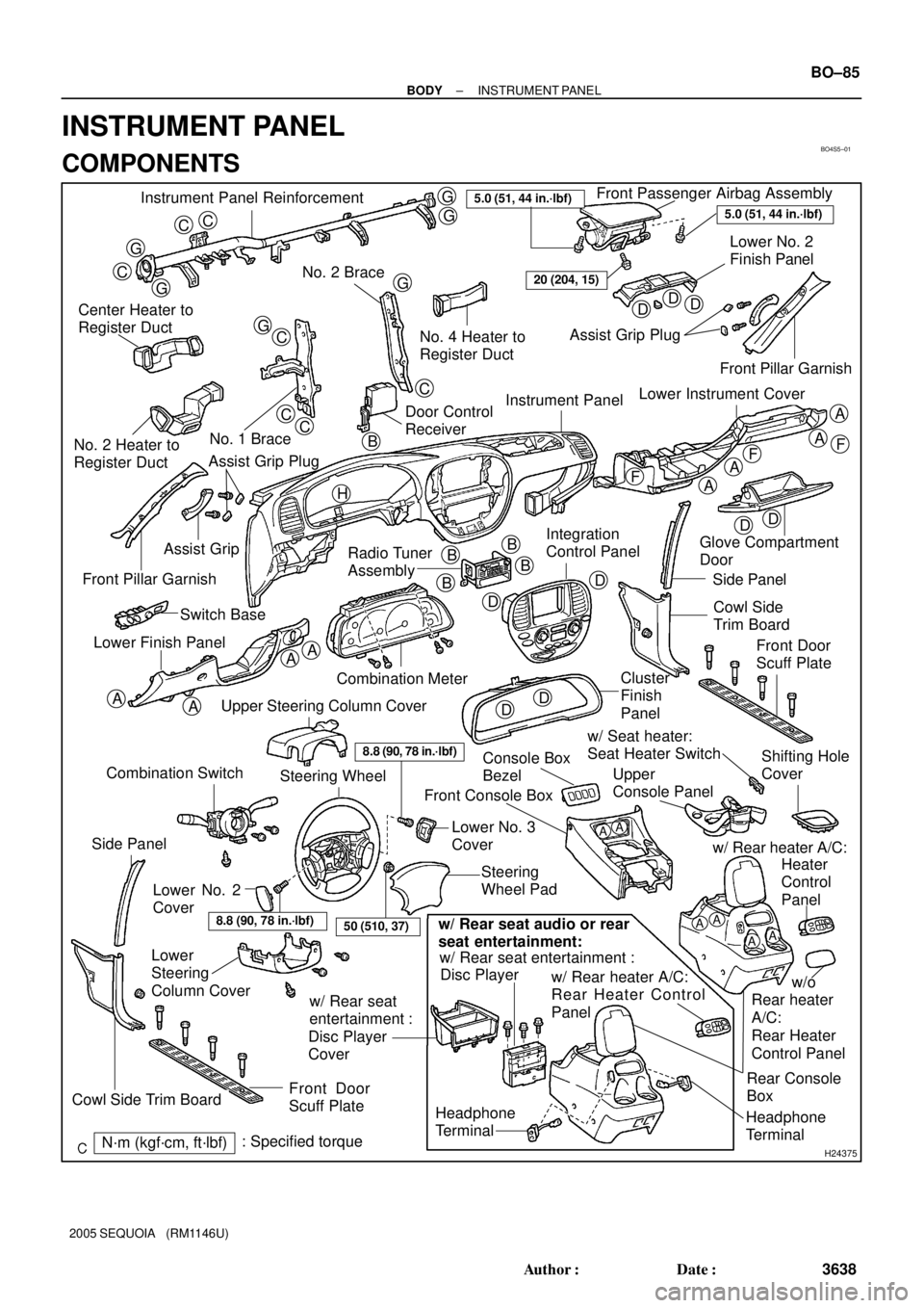
INSTRUMENT PANEL
COMPONENTS
Page 3650 of 4323

BO4HL±02
H24383Claw
H16716
2 Clips
H16717
Clip
± BODYINSTRUMENT PANEL
BO±89
3642 Author�: Date�:
2005 SEQUOIA (RM1146U)
REMOVAL
1. DISCONNECT CABLE FROM NEGATIVE BATTERY
TERMINAL
Wait for 90 seconds after disconnecting the cable to prevent the
airbag working.
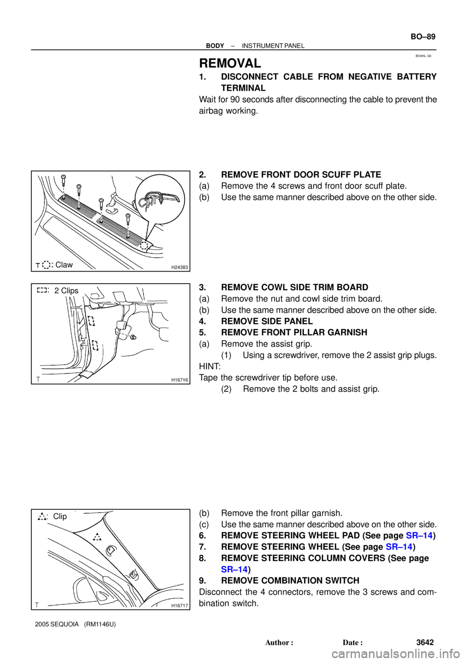
2. REMOVE FRONT DOOR SCUFF PLATE
(a) Remove the 4 screws and front door scuff plate.
(b) Use the same manner described above on the other side.
3. REMOVE COWL SIDE TRIM BOARD
(a) Remove the nut and cowl side trim board.
(b) Use the same manner described above on the other side.
4. REMOVE SIDE PANEL
5. REMOVE FRONT PILLAR GARNISH
(a) Remove the assist grip.
(1) Using a screwdriver, remove the 2 assist grip plugs.
HINT:
Tape the screwdriver tip before use.
(2) Remove the 2 bolts and assist grip.
(b) Remove the front pillar garnish.
(c) Use the same manner described above on the other side.
6. REMOVE STEERING WHEEL PAD (See page SR±14)
7. REMOVE STEERING WHEEL (See page SR±14)
8. REMOVE STEERING COLUMN COVERS (See page
SR±14)
9. REMOVE COMBINATION SWITCH
Disconnect the 4 connectors, remove the 3 screws and com-
bination switch.
Page 3653 of 4323

H16749
H18899
H243734 Claws
H16751
2 Clips
H21029
BO±92
± BODYINSTRUMENT PANEL
3645 Author�: Date�:
2005 SEQUOIA (RM1146U)
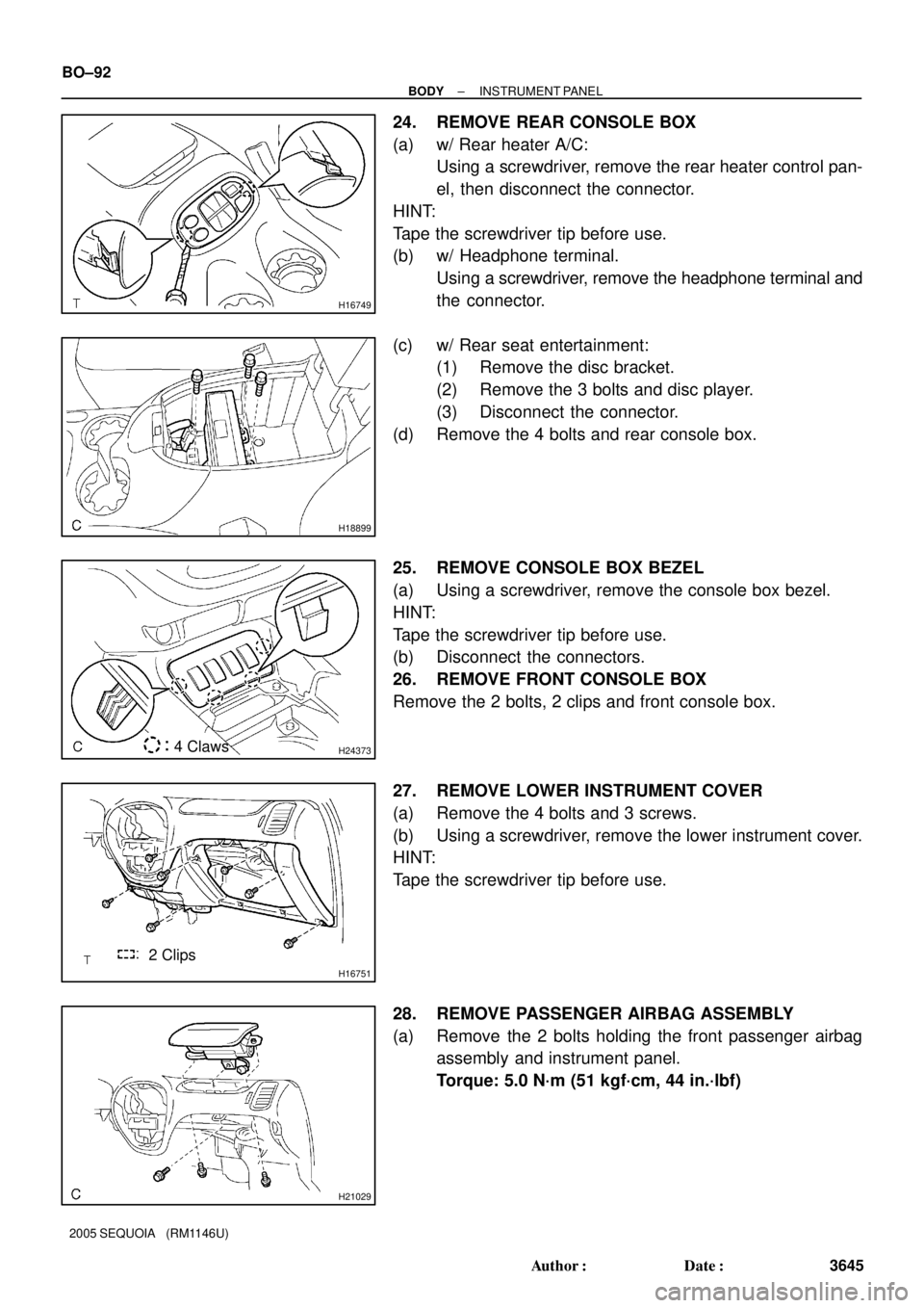
24. REMOVE REAR CONSOLE BOX
(a) w/ Rear heater A/C:
Using a screwdriver, remove the rear heater control pan-
el, then disconnect the connector.
HINT:
Tape the screwdriver tip before use.
(b) w/ Headphone terminal.
Using a screwdriver, remove the headphone terminal and
the connector.
(c) w/ Rear seat entertainment:
(1) Remove the disc bracket.
(2) Remove the 3 bolts and disc player.
(3) Disconnect the connector.
(d) Remove the 4 bolts and rear console box.
25. REMOVE CONSOLE BOX BEZEL
(a) Using a screwdriver, remove the console box bezel.
HINT:
Tape the screwdriver tip before use.
(b) Disconnect the connectors.
26. REMOVE FRONT CONSOLE BOX
Remove the 2 bolts, 2 clips and front console box.
27. REMOVE LOWER INSTRUMENT COVER
(a) Remove the 4 bolts and 3 screws.
(b) Using a screwdriver, remove the lower instrument cover.
HINT:
Tape the screwdriver tip before use.
28. REMOVE PASSENGER AIRBAG ASSEMBLY
(a) Remove the 2 bolts holding the front passenger airbag
assembly and instrument panel.
Torque: 5.0 N´m (51 kgf´cm, 44 in.´lbf)
Page 3658 of 4323
BO43A±02
± BODYINSTRUMENT PANEL
BO±97
3650 Author�: Date�:
2005 SEQUOIA (RM1146U)
INSTALLATION
Installation is in the reverse order of removal (See page BO±89).
1. CONNECT CABLE TO NEGATIVE BATTERY TERMINAL
2. PERFORM INITIALIZATION (See page IN±20)
Some systems need initialization when disconnecting the cable from the negative battery terminal.