Page 1153 of 2572
H10600H01012C92968
C92969H10600H01012C92968
C92969H42126
Airbag
Sensor
Rear LHAirbag
Sensor
Assy
Center
DTC B1154/38
DTC B1155/39
TC CG
05-1370
- DIAGNOSTICSSUPPLEMENTAL RESTRAINT SYSTEM
1560 Author�: Date�:
2005 HIGHLANDER REPAIR MANUAL (RM1144U)
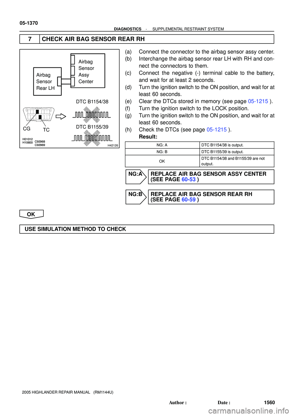
7 CHECK AIR BAG SENSOR REAR RH
(a) Connect the connector to the airbag sensor assy center.
(b) Interchange the airbag sensor rear LH with RH and con-
nect the connectors to them.
(c) Connect the negative (-) terminal cable to the battery,
and wait for at least 2 seconds.
(d) Turn the ignition switch to the ON position, and wait for at
least 60 seconds.
(e) Clear the DTCs stored in memory (see page 05-1215).
(f) Turn the ignition switch to the LOCK position.
(g) Turn the ignition switch to the ON position, and wait for at
least 60 seconds.
(h) Check the DTCs (see page 05-1215).
Result:
NG: ADTC B1154/38 is output.
NG: BDTC B1155/39 is output.
OKDTC B1154/38 and B1155/39 are not
output.
NG:A REPLACE AIR BAG SENSOR ASSY CENTER
(SEE PAGE 60-53)
NG:B REPLACE AIR BAG SENSOR REAR RH
(SEE PAGE 60-59)
OK
USE SIMULATION METHOD TO CHECK
Page 1154 of 2572
H43054
Airbag Sensor Rear LH Airbag Sensor Assy Center
R G W B
ESCL
CSL-
CSL+ VUCL
4
3 2 1
A161
15 1413
ESCL
CSL-
CSL+ VUCL
A16 A16 A16 S32
(*1)
(*1)
(*1)
(*1)
*1 w/ Curtain Shield Airbag
- DIAGNOSTICSSUPPLEMENTAL RESTRAINT SYSTEM
05-1371
1561 Author�: Date�:
2005 HIGHLANDER REPAIR MANUAL (RM1144U)
DTC B1155/39 AIRBAG SENSOR REAR (LH)
MALFUNCTION
CIRCUIT DESCRIPTION
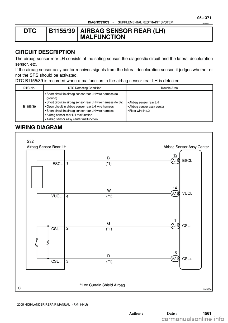
The airbag sensor rear LH consists of the safing sensor, the diagnostic circuit and the lateral deceleration
sensor, etc.
If the airbag sensor assy center receives signals from the lateral deceleration sensor, it judges whether or
not the SRS should be activated.
DTC B1155/39 is recorded when a malfunction in the airbag sensor rear LH is detected.
DTC No.DTC Detecting ConditionTrouble Area
B1155/39
�Short circuit in airbag sensor rear LH wire harness (to
ground)
�Short circuit in airbag sensor rear LH wire harness (to B+)
�Open circuit in airbag sensor rear LH wire harness
�Short circuit in airbag sensor rear LH wire harness
�Airbag sensor rear LH malfunction
�Airbag sensor assy center malfunction
�Airbag sensor rear LH
�Airbag sensor assy center
�Floor wire No.2
WIRING DIAGRAM
05IVV-01
Page 1155 of 2572
H01007
H10600C92969H01007
H10600C92969H42127
Airbag
Sensor
Assy
Center
DLC3
CG
TCDTC B1155/39
Airbag
Sensor
Rear LH
05-1372
- DIAGNOSTICSSUPPLEMENTAL RESTRAINT SYSTEM
1562 Author�: Date�:
2005 HIGHLANDER REPAIR MANUAL (RM1144U)
INSPECTION PROCEDURE
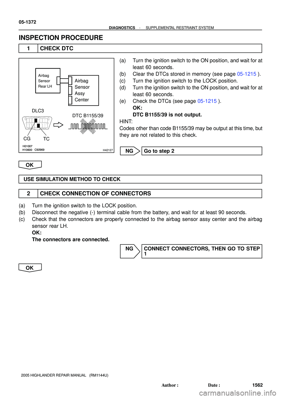
1 CHECK DTC
(a) Turn the ignition switch to the ON position, and wait for at
least 60 seconds.
(b) Clear the DTCs stored in memory (see page 05-1215).
(c) Turn the ignition switch to the LOCK position.
(d) Turn the ignition switch to the ON position, and wait for at
least 60 seconds.
(e) Check the DTCs (see page 05-1215).
OK:
DTC B1155/39 is not output.
HINT:
Codes other than code B1155/39 may be output at this time, but
they are not related to this check.
NG Go to step 2
OK
USE SIMULATION METHOD TO CHECK
2 CHECK CONNECTION OF CONNECTORS
(a) Turn the ignition switch to the LOCK position.
(b) Disconnect the negative (-) terminal cable from the battery, and wait for at least 90 seconds.
(c) Check that the connectors are properly connected to the airbag sensor assy center and the airbag
sensor rear LH.
OK:
The connectors are connected.
NG CONNECT CONNECTORS, THEN GO TO STEP
1
OK
Page 1156 of 2572
C91384C91385H01010C82600C91384C91385H01010C82600H43148
Airbag Sensor
Rear LHAirbag
Sensor
Assy
Center Floor Wire No.2
CSL-
ESCL
VUCL
CSL+ SST
SST
BA D
C
VUCL ESCL CSL-CSL+A16 S32
H01010C82600H01010C82600H42486
Airbag Sensor
Rear LHAirbag
Sensor
Assy
Center Floor Wire No.2
VUCL
CSL+
CSL-
CDA D
ESCL
A16
- DIAGNOSTICSSUPPLEMENTAL RESTRAINT SYSTEM
05-1373
1563 Author�: Date�:
2005 HIGHLANDER REPAIR MANUAL (RM1144U)
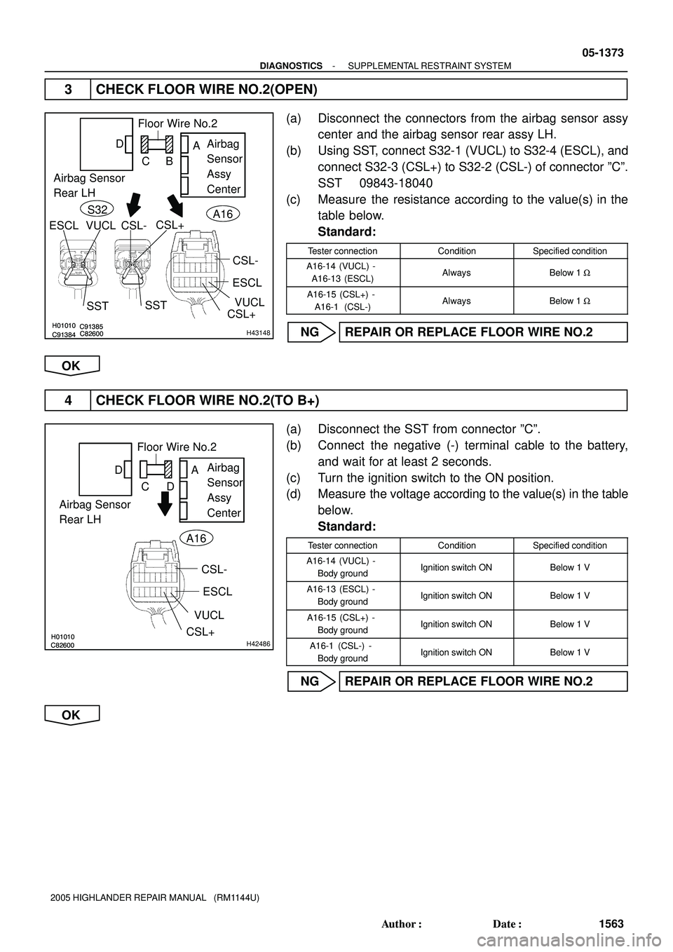
3 CHECK FLOOR WIRE NO.2(OPEN)
(a) Disconnect the connectors from the airbag sensor assy
center and the airbag sensor rear assy LH.
(b) Using SST, connect S32-1 (VUCL) to S32-4 (ESCL), and
connect S32-3 (CSL+) to S32-2 (CSL-) of connector ºCº.
SST 09843-18040
(c) Measure the resistance according to the value(s) in the
table below.
Standard:
Tester connectionConditionSpecified condition
A16-14 (VUCL) -
A16-13 (ESCL)AlwaysBelow 1 W
A16-15 (CSL+) -
A16-1 (CSL-)AlwaysBelow 1 W
NG REPAIR OR REPLACE FLOOR WIRE NO.2
OK
4 CHECK FLOOR WIRE NO.2(TO B+)
(a) Disconnect the SST from connector ºCº.
(b) Connect the negative (-) terminal cable to the battery,
and wait for at least 2 seconds.
(c) Turn the ignition switch to the ON position.
(d) Measure the voltage according to the value(s) in the table
below.
Standard:
Tester connectionConditionSpecified condition
A16-14 (VUCL) -
Body groundIgnition switch ONBelow 1 V
A16-13 (ESCL) -
Body groundIgnition switch ONBelow 1 V
A16-15 (CSL+) -
Body groundIgnition switch ONBelow 1 V
A16-1 (CSL-) -
Body groundIgnition switch ONBelow 1 V
NG REPAIR OR REPLACE FLOOR WIRE NO.2
OK
Page 1157 of 2572
H01010C82600H01010C82600H42486
Airbag Sensor
Rear LHAirbag
Sensor
Assy
Center Floor Wire No.2
VUCL
CSL+
A
B C D
CSL-
ESCL A16
H01010C82600H01010C82600H42486
Airbag Sensor
Rear LHAirbag
Sensor
Assy
Center Floor Wire No.2
VUCL
CSL+
A
B C D
CSL-
ESCL A16
05-1374
- DIAGNOSTICSSUPPLEMENTAL RESTRAINT SYSTEM
1564 Author�: Date�:
2005 HIGHLANDER REPAIR MANUAL (RM1144U)
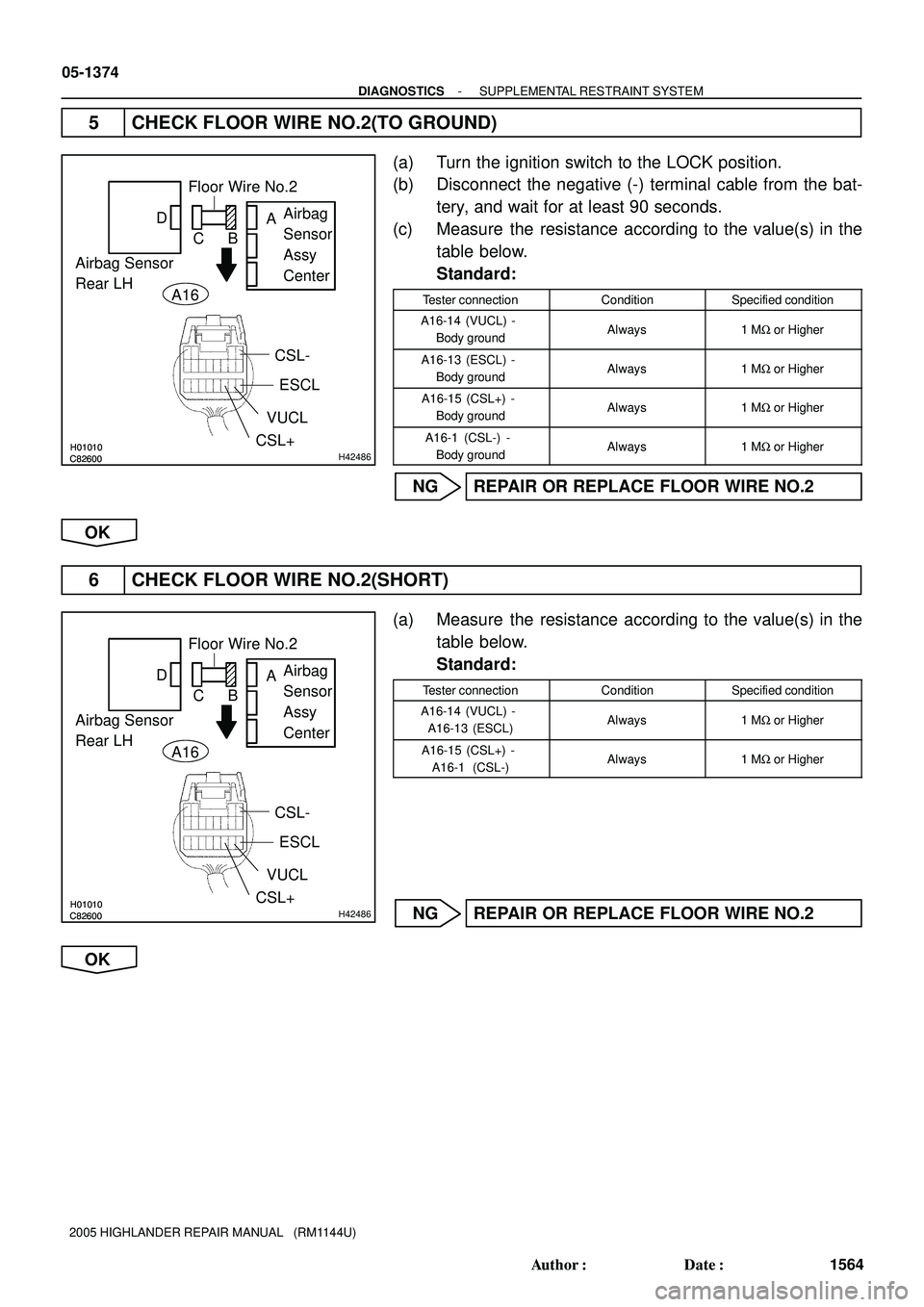
5 CHECK FLOOR WIRE NO.2(TO GROUND)
(a) Turn the ignition switch to the LOCK position.
(b) Disconnect the negative (-) terminal cable from the bat-
tery, and wait for at least 90 seconds.
(c) Measure the resistance according to the value(s) in the
table below.
Standard:
Tester connectionConditionSpecified condition
A16-14 (VUCL) -
Body groundAlways1 MW or Higher
A16-13 (ESCL) -
Body groundAlways1 MW or Higher
A16-15 (CSL+) -
Body groundAlways1 MW or Higher
A16-1 (CSL-) -
Body groundAlways1 MW or Higher
NG REPAIR OR REPLACE FLOOR WIRE NO.2
OK
6 CHECK FLOOR WIRE NO.2(SHORT)
(a) Measure the resistance according to the value(s) in the
table below.
Standard:
Tester connectionConditionSpecified condition
A16-14 (VUCL) -
A16-13 (ESCL)Always1 MW or Higher
A16-15 (CSL+) -
A16-1 (CSL-)Always1 MW or Higher
NG REPAIR OR REPLACE FLOOR WIRE NO.2
OK
Page 1158 of 2572
H01007
H10600C92968
C92969H01007
H10600C92968
C92969H42128
Airbag
Sensor
Assy
Center
DLC3
CG
TCDTC B1154/38
DTC B1155/39
Airbag
Sensor
Rear RH
- DIAGNOSTICSSUPPLEMENTAL RESTRAINT SYSTEM
05-1375
1565 Author�: Date�:
2005 HIGHLANDER REPAIR MANUAL (RM1144U)
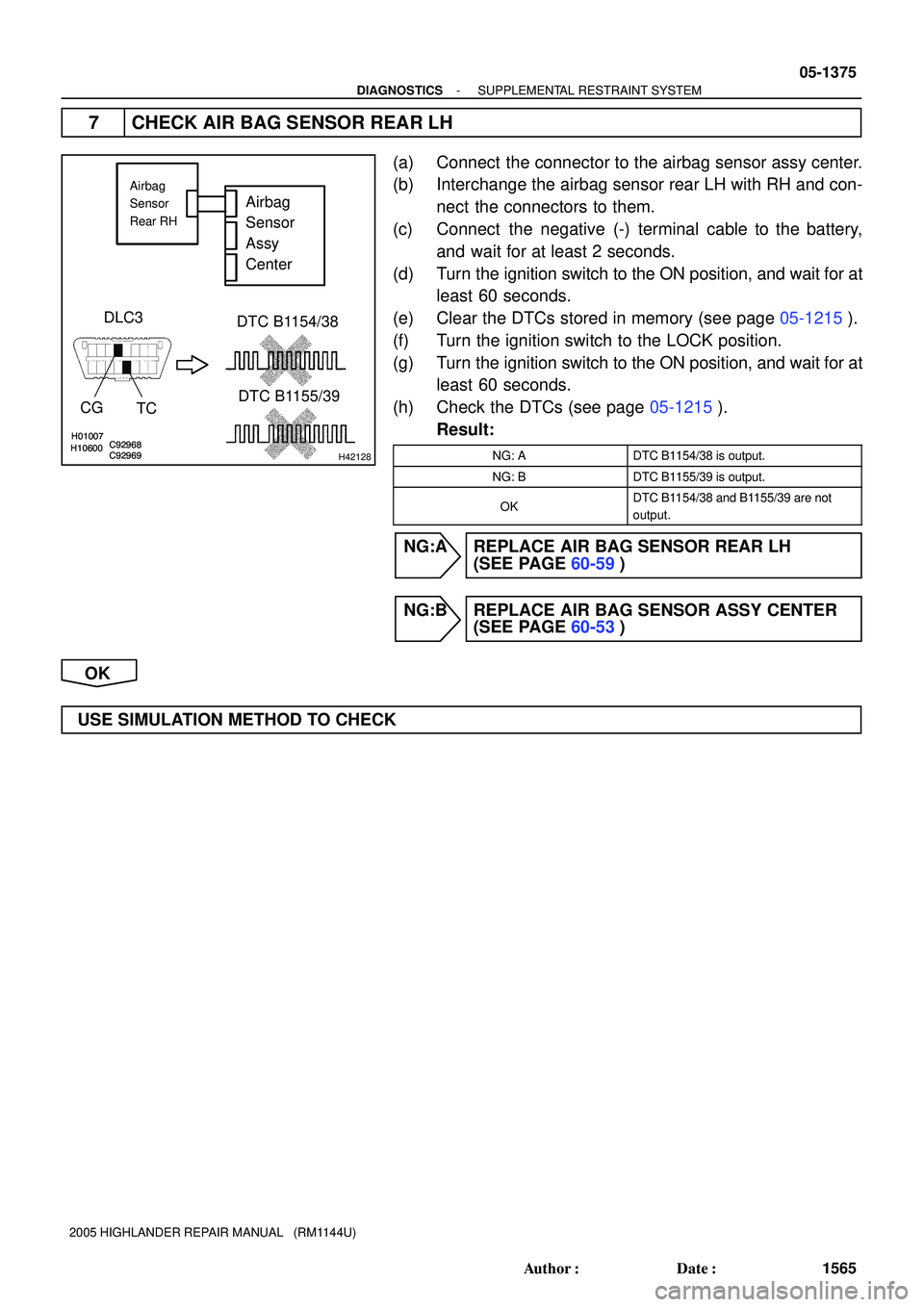
7 CHECK AIR BAG SENSOR REAR LH
(a) Connect the connector to the airbag sensor assy center.
(b) Interchange the airbag sensor rear LH with RH and con-
nect the connectors to them.
(c) Connect the negative (-) terminal cable to the battery,
and wait for at least 2 seconds.
(d) Turn the ignition switch to the ON position, and wait for at
least 60 seconds.
(e) Clear the DTCs stored in memory (see page 05-1215).
(f) Turn the ignition switch to the LOCK position.
(g) Turn the ignition switch to the ON position, and wait for at
least 60 seconds.
(h) Check the DTCs (see page 05-1215).
Result:
NG: ADTC B1154/38 is output.
NG: BDTC B1155/39 is output.
OKDTC B1154/38 and B1155/39 are not
output.
NG:A REPLACE AIR BAG SENSOR REAR LH
(SEE PAGE 60-59)
NG:B REPLACE AIR BAG SENSOR ASSY CENTER
(SEE PAGE 60-53)
OK
USE SIMULATION METHOD TO CHECK
Page 1159 of 2572
H43058
Airbag Sensor Assy Center
C19
Curtain Shield Squib RH
8
A18
ICR+
7
A18ICR- 1
22
Y
(*1 *3)Y
1
BK2 Y-B Y-B(*1 *3)
(*1 *3) (*1 *3)BK2
*1: w/ Rear Seat Entertainment System
*2: w/o Rear Seat Entertainment System
*3: w/ Curtain Shield Airbag
*4: w/o Curtain Shield AirbagY
(*2 *3)
Y-B
(*2 *3) 05-1376
- DIAGNOSTICSSUPPLEMENTAL RESTRAINT SYSTEM
1566 Author�: Date�:
2005 HIGHLANDER REPAIR MANUAL (RM1144U)
DTC B1160/83 SHORT IN CURTAIN SHIELD SQUIB (RH)
CIRCUIT
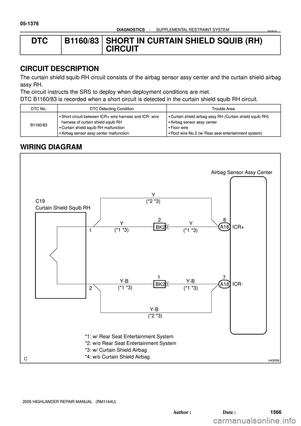
CIRCUIT DESCRIPTION
The curtain shield squib RH circuit consists of the airbag sensor assy center and the curtain shield airbag
assy RH.
The circuit instructs the SRS to deploy when deployment conditions are met.
DTC B1160/83 is recorded when a short circuit is detected in the curtain shield squib RH circuit.
DTC No.DTC Detecting ConditionTrouble Area
B1160/83
�Short circuit between ICR+ wire harness and ICR- wire
harness of curtain shield squib RH
�Curtain shield squib RH malfunction
�Airbag sensor assy center malfunction�Curtain shield airbag assy RH (Curtain shield squib RH)
�Airbag sensor assy center
�Floor wire
�Roof wire No.2 (w/ Rear seat entertainment system)
WIRING DIAGRAM
05IVW-02
Page 1160 of 2572
H41465H41465H43068
Curtain Shield
Squib RHAirbag
Sensor
Assy
Center Floor Wire
A
B C D
ICR+ ICR-C19
- DIAGNOSTICSSUPPLEMENTAL RESTRAINT SYSTEM
05-1377
1567 Author�: Date�:
2005 HIGHLANDER REPAIR MANUAL (RM1144U)
INSPECTION PROCEDURE
1 CHECK VEHICLE CONDITION
(a) Check whether or not the vehicle is equipped with the rear seat entertainment system.
Result:
A: w/o Rear seat entertainment system
B: w/ Rear seat entertainment system
B Go to step 6
A
2 CHECK CONNECTOR
(a) Turn the ignition switch to the LOCK position.
(b) Disconnect the negative (-) terminal cable from the battery, and wait for at least for 90 seconds.
(c) Disconnect the connectors from the curtain shield airbag assy RH.
(d) Check that the floor wire connector (on the curtain shield airbag assy RH side) is not damaged.
OK:
The lock button is not disengaged, or the claw of the lock is not deformed or damaged.
B REPAIR OR REPLACE FLOOR WIRE
A
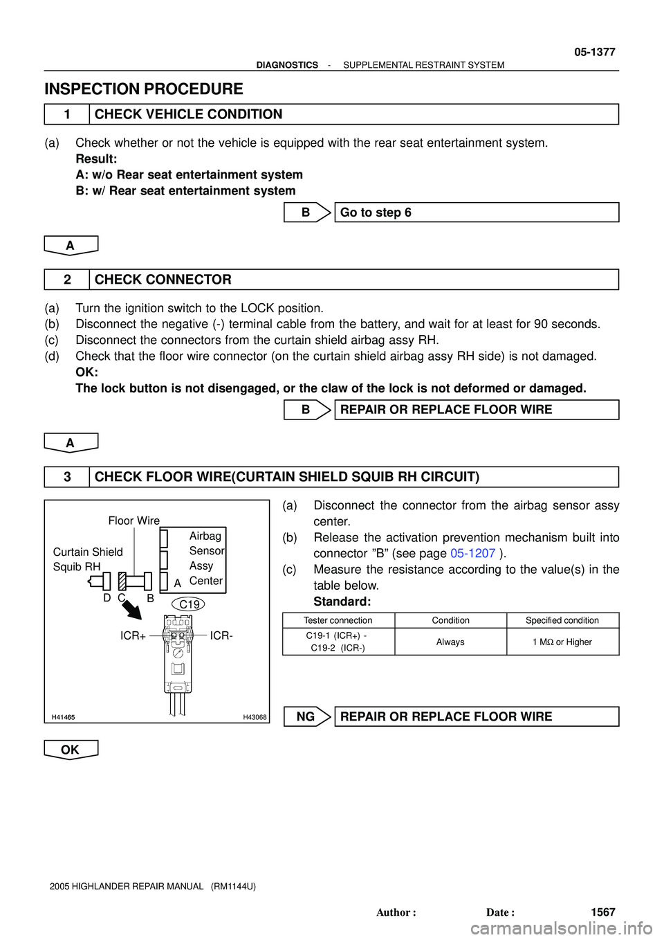
3 CHECK FLOOR WIRE(CURTAIN SHIELD SQUIB RH CIRCUIT)
(a) Disconnect the connector from the airbag sensor assy
center.
(b) Release the activation prevention mechanism built into
connector ºBº (see page 05-1207).
(c) Measure the resistance according to the value(s) in the
table below.
Standard:
Tester connectionConditionSpecified condition
C19-1 (ICR+) -
C19-2 (ICR-)Always1 MW or Higher
NG REPAIR OR REPLACE FLOOR WIRE
OK