Page 1145 of 2572

H42467
LSP+ Airbag
Sensor
Assy
Center
Seat
Position
Airbag
Sensor
A
B
C DFloor Wire No.2
2
LSP- 4
Service Wire
B19
LSP+
LSP-
*1: w/ Side and Curtain Shield Airbag
*2: w/o Side and Curtain Shield Airbag
A16A16*2
*1
H42459
Airbag
Sensor
Assy
Center
LSP+LSP- Floor Wire No.2
Seat Position
Airbag SensorA
B C D
A16
LSP+
LSP- *2A16*1
*1: w/ Side and Curtain Shield Airbag
*2: w/o Side and Curtain Shield Airbag
05-1362
- DIAGNOSTICSSUPPLEMENTAL RESTRAINT SYSTEM
1552 Author�: Date�:
2005 HIGHLANDER REPAIR MANUAL (RM1144U)
3 CHECK FLOOR WIRE NO.2(OPEN)
(a) Disconnect the connectors from the airbag sensor assy
center and the seat position airbag sensor.
(b) Using a service wire, connect B19-2 and B19-4 of con-
nector ºCº.
NOTICE:
Do not forcibly insert a service wire into the terminals of the
connector when connecting.
(c) Measure the resistance according to the value(s) in the
table below.
Standard:
w/ Side and curtain shield airbag:
Tester connectionConditionSpecified condition
A16-4 (LSP+) -
A16-3 (LSP-)AlwaysBelow 1 W
w/o Side and curtain shield airbag:
Tester connectionConditionSpecified condition
A16-3 (LSP+) -
A16-8 (LSP-)AlwaysBelow 1 W
NG REPAIR OR REPLACE FLOOR WIRE NO.2
OK
4 CHECK FLOOR WIRE NO.2(TO B+)
(a) Disconnect the service wire from connector ºCº.
(b) Connect the negative (-) terminal cable to the battery,
and wait for at least 2 seconds.
(c) Turn the ignition switch to the ON position.
(d) Measure the voltage according to the value(s) in the table
below.
Standard:
w/ Side and curtain shield airbag:
Tester connectionConditionSpecified condition
A16-4 (LSP+) -
Body groundIgnition switch ONBelow 1 V
A16-3 (LSP-) -
Body groundIgnition switch ONBelow 1 V
w/o Side and curtain shield airbag:
Tester connectionConditionSpecified condition
A16-3 (LSP+) -
Body groundIgnition switch ONBelow 1 V
A16-8 (LSP-) -
Body groundIgnition switch ONBelow 1 V
NG REPAIR OR REPLACE FLOOR WIRE NO.2
OK
Page 1146 of 2572

H42459
Airbag
Sensor
Assy
Center
LSP+LSP- Floor Wire No.2
Seat Position
Airbag SensorA
B C D
A16
LSP+
LSP- *2A16*1
*1: w/ Side and Curtain Shield Airbag
*2: w/o Side and Curtain Shield Airbag
H42459
Airbag
Sensor
Assy
Center
LSP+LSP- Floor Wire No.2
Seat Position
Airbag SensorA
B C D
A16
LSP+
LSP- *2A16*1
*1: w/ Side and Curtain Shield Airbag
*2: w/o Side and Curtain Shield Airbag
- DIAGNOSTICSSUPPLEMENTAL RESTRAINT SYSTEM
05-1363
1553 Author�: Date�:
2005 HIGHLANDER REPAIR MANUAL (RM1144U)
5 CHECK FLOOR WIRE NO.2(TO GROUND)
(a) Turn the ignition switch to the LOCK position.
(b) Disconnect the negative (-) terminal cable from the bat-
tery, and wait for at least 90 seconds.
(c) Measure the resistance according to the value(s) in the
table below.
Standard:
w/ Side and curtain shield airbag:
Tester connectionConditionSpecified condition
A16-4 (LSP+) -
Body groundAlways1 MW or Higher
A16-3 (LSP-) -
Body groundAlways1 MW or Higher
w/o Side and curtain shield airbag:
Tester connectionConditionSpecified condition
A16-3 (LSP+) -
Body groundAlways1 MW or Higher
A16-8 (LSP-) -
Body groundAlways1 MW or Higher
NG REPAIR OR REPLACE FLOOR WIRE NO.2
OK
6 CHECK FLOOR WIRE NO.2(SHORT)
(a) Measure the resistance according to the value(s) in the
table below.
Standard:
w/ Side and curtain shield airbag:
Tester connectionConditionSpecified condition
A16-4 (LSP+) -
A16-3 (LSP-)Always1 MW or Higher
w/o Side and curtain shield airbag:
Tester connectionConditionSpecified condition
A16-3 (LSP+) -
A16-8 (LSP-)Always1 MW or Higher
NG REPAIR OR REPLACE FLOOR WIRE NO.2
OK
Page 1147 of 2572
H10600 C91522H01007H10600 C91522H01007H42468
Airbag
Sensor
Assy
Center Seat
Position
Airbag
Sensor
DTC B1153/25 DLC3
CG
TC
05-1364
- DIAGNOSTICSSUPPLEMENTAL RESTRAINT SYSTEM
1554 Author�: Date�:
2005 HIGHLANDER REPAIR MANUAL (RM1144U)
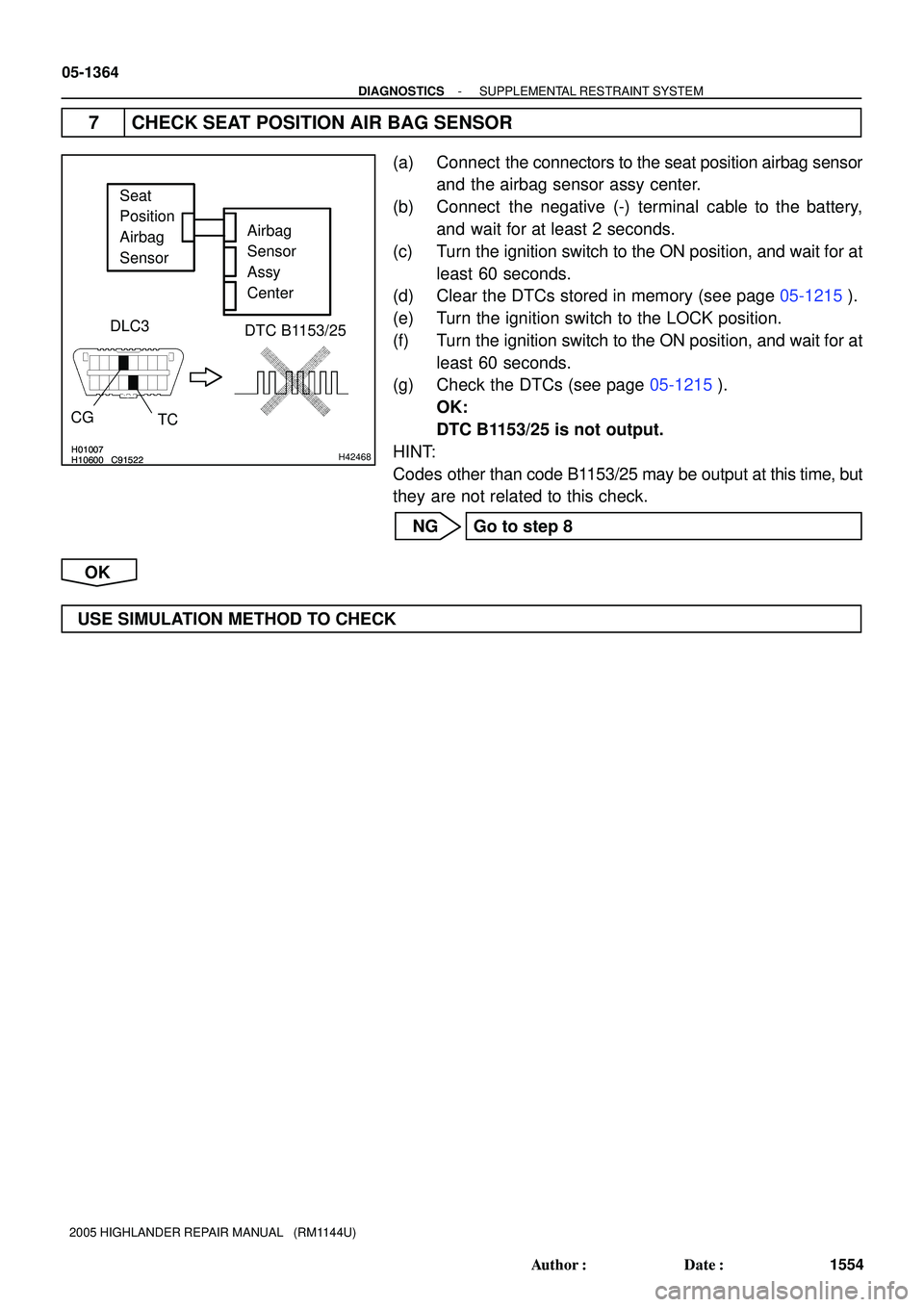
7 CHECK SEAT POSITION AIR BAG SENSOR
(a) Connect the connectors to the seat position airbag sensor
and the airbag sensor assy center.
(b) Connect the negative (-) terminal cable to the battery,
and wait for at least 2 seconds.
(c) Turn the ignition switch to the ON position, and wait for at
least 60 seconds.
(d) Clear the DTCs stored in memory (see page 05-1215).
(e) Turn the ignition switch to the LOCK position.
(f) Turn the ignition switch to the ON position, and wait for at
least 60 seconds.
(g) Check the DTCs (see page 05-1215).
OK:
DTC B1153/25 is not output.
HINT:
Codes other than code B1153/25 may be output at this time, but
they are not related to this check.
NG Go to step 8
OK
USE SIMULATION METHOD TO CHECK
Page 1148 of 2572

H10600 C91522H01007H10600 C91522H01007H42468
Airbag
Sensor
Assy
Center Seat
Position
Airbag
Sensor
DTC B1153/25 DLC3
CG
TC
- DIAGNOSTICSSUPPLEMENTAL RESTRAINT SYSTEM
05-1365
1555 Author�: Date�:
2005 HIGHLANDER REPAIR MANUAL (RM1144U)
8 REPLACE SEAT POSITION AIR BAG SENSOR
(a) Turn the ignition switch to the LOCK position.
(b) Disconnect the negative (-) terminal cable from the battery, and wait for at least 90 seconds.
(c) Replace the seat position airbag sensor (see page 60-61).
9 CHECK AIR BAG SENSOR ASSY CENTER
(a) Connect the negative (-) terminal cable to the battery,
and wait for at least 2 seconds.
(b) Turn the ignition switch to the ON position, and wait for at
least 60 seconds.
(c) Clear the DTCs stored in memory (see page 05-1215).
(d) Turn the ignition switch to the LOCK position.
(e) Turn the ignition switch to the ON position, and wait for at
least 60 seconds.
(f) Check the DTCs (see page 05-1215).
OK:
DTC B1153/25 is not output.
HINT:
Codes other than code B1153/25 may be output at this time, but
they are not related to this check.
NG REPLACE AIR BAG SENSOR ASSY CENTER
(SEE PAGE 60-53)
OK
END
Page 1149 of 2572

(*1)
(*1)
(*1)
*1 w/ Curtain Shield Airbag 05-1366
- DI")
H43054
Airbag Sensor Rear RH Airbag Sensor Assy Center
R G W B
ESCR
CSR-
CSR+ VUCR
4
3 2 1
A184
18 1920
ESCR
CSR-
CSR+ VUCR
A18 A18 A18 S33
(*1)
(*1)
(*1)
(*1)
*1 w/ Curtain Shield Airbag 05-1366
- DIAGNOSTICSSUPPLEMENTAL RESTRAINT SYSTEM
1556 Author�: Date�:
2005 HIGHLANDER REPAIR MANUAL (RM1144U)
DTC B1154/38 AIRBAG SENSOR REAR (RH)
MALFUNCTION
CIRCUIT DESCRIPTION
The airbag sensor rear RH consists of the safing sensor, the diagnostic circuit and the lateral deceleration
sensor, etc.
If the airbag sensor assy center receives signals from the lateral deceleration sensor, it judges whether or
not the SRS should be activated.
DTC B1154/38 is recorded when a malfunction in the airbag sensor rear RH is detected.
DTC No.DTC Detecting ConditionTrouble Area
B1154/38
�Short circuit in airbag sensor rear RH wire harness (to
ground)
�Short circuit in airbag sensor rear RH wire harness (to B+)
�Open circuit in airbag sensor rear RH wire harness
�Short circuit in airbag sensor rear RH wire harness
�Airbag sensor rear RH malfunction
�Airbag sensor assy center malfunction
�Airbag sensor rear RH
�Airbag sensor assy center
�Floor wire
WIRING DIAGRAM
05IVU-01
Page 1150 of 2572

H10600H01012C92968
H10600H01012C92968H42125
Airbag
Sensor
Assy
Center
DLC3
CG
TCDTC B1154/38
Airbag
Sensor
Rear RH
- DIAGNOSTICSSUPPLEMENTAL RESTRAINT SYSTEM
05-1367
1557 Author�: Date�:
2005 HIGHLANDER REPAIR MANUAL (RM1144U)
INSPECTION PROCEDURE
1 CHECK DTC
(a) Turn the ignition switch to the ON position, and wait for at
least 60 seconds.
(b) Clear the DTCs stored in memory (see page 05-1215).
(c) Turn the ignition switch to the LOCK position.
(d) Turn the ignition switch to the ON position, and wait for at
least 60 seconds.
(e) Check the DTCs (see page 05-1215).
OK:
DTC B1154/38 is not output.
HINT:
Codes other than code B1154/38 may be output at this time, but
they are not related to this check.
NG Go to step 2
OK
USE SIMULATION METHOD TO CHECK
2 CHECK CONNECTION OF CONNECTORS
(a) Turn the ignition switch to the LOCK position.
(b) Disconnect the negative (-) terminal cable from the battery, and wait for at least 90 seconds.
(c) Check that the connectors are properly connected to the airbag sensor assy center and the airbag
sensor rear RH.
OK:
The connectors are connected.
NG CONNECT CONNECTORS, THEN GO TO STEP
1
OK
Page 1151 of 2572

H01015
C91384
C91385 C82599H01015
C91384
C91385 C82599
H42483
Airbag Sensor
Rear RHAirbag
Sensor
Assy
Center Floor Wire
CSR-
ESCR
VUCR
CSR+
SST
A
B C D
ESCR VUCR
CSR- CSR+
A18
S33
H01015
C82599H01015
C82599H42484
Airbag Sensor
Rear RHAirbag
Sensor
Assy
Center Floor Wire
CSR+ VUCR ESCRA
D
CB
CSR-
A18
05-1368
- DIAGNOSTICSSUPPLEMENTAL RESTRAINT SYSTEM
1558 Author�: Date�:
2005 HIGHLANDER REPAIR MANUAL (RM1144U)
3 CHECK FLOOR WIRE(OPEN)
(a) Disconnect the connectors from the airbag sensor assy
center and the airbag sensor rear assy RH.
(b) Using SST, connect S33-4 (VUCR) to S33-1 (ESCR),
and connect S33-3 (CSR+) to S33-2 (CSR-) of connec-
tor ºCº.
SST 09843-18040
(c) Measure the resistance according to the value(s) in the
table below.
Standard:
Tester connectionConditionSpecified condition
A18-19 (VUCR) -
A18-20 (ESCR)AlwaysBelow 1 W
A18-18 (CSR+) -
A18-4 (CSR-)AlwaysBelow 1 W
NG REPAIR OR REPLACE FLOOR WIRE
OK
4 CHECK FLOOR WIRE(TO B+)
(a) Disconnect the SST from connector ºCº.
(b) Connect the negative (-) terminal cable to the battery,
and wait for at least 2 seconds.
(c) Turn the ignition switch to the ON position.
(d) Measure the voltage according to the value(s) in the table
below.
Standard:
Tester connectionConditionSpecified condition
A18-19 (VUCR) -
Body groundIgnition switch ONBelow 1 V
A18-20 (ESCR) -
Body groundIgnition switch ONBelow 1 V
A18-18 (CSR+) -
Body groundIgnition switch ONBelow 1 V
A18-4 (CSR-) -
Body groundIgnition switch ONBelow 1 V
NG REPAIR OR REPLACE FLOOR WIRE
OK
Page 1152 of 2572

H01015
C82599H01015
C82599H42484
Airbag Sensor
Rear RHAirbag
Sensor
Assy
Center Floor Wire
CSR+ VUCR ESCRCA DB
CSR-
A18
H01015
C82599H01015
C82599H42484
Airbag Sensor
Rear RHAirbag
Sensor
Assy
Center Floor Wire
CSR+ VUCR ESCRCA DB
CSR-
A18
- DIAGNOSTICSSUPPLEMENTAL RESTRAINT SYSTEM
05-1369
1559 Author�: Date�:
2005 HIGHLANDER REPAIR MANUAL (RM1144U)
5 CHECK FLOOR WIRE(TO GROUND)
(a) Turn the ignition switch to the LOCK position.
(b) Disconnect the negative (-) terminal cable from the bat-
tery, and wait for at least 90 seconds.
(c) Measure the resistance according to the value(s) in the
table below.
Standard:
Tester connectionConditionSpecified condition
A18-19 (VUCR) -
Body groundAlways1 MW or Higher
A18-20 (ESCR) -
Body groundAlways1 MW or Higher
A18-18 (CSR+) -
Body groundAlways1 MW or Higher
A18-4 (CSR-) -
Body groundAlways1 MW or Higher
NG REPAIR OR REPLACE FLOOR WIRE
OK
6 CHECK FLOOR WIRE(SHORT)
(a) Measure the resistance according to the value(s) in the
table below.
Standard:
Tester connectionConditionSpecified condition
A18-19 (VUCR) -
A18-20 (ESCR)Always1 MW or Higher
A18-18 (CSR+) -
A18-4 (CSR-)Always1 MW or Higher
NG REPAIR OR REPLACE FLOOR WIRE
OK