Page 1128 of 2572
H03354C81305H43447
Engine Room
Main Wire
-SL
+SLAirbag
Sensor
Assy
Center
Airbag Sensor
Front LH
A
B C D E FCowl Wire
IK1
H03354C81305H43447
Engine Room
Main Wire
-SL
+SLAirbag
Sensor
Assy
Center
Airbag Sensor
Front LH
A
B C D E FCowl Wire
IK1
- DIAGNOSTICSSUPPLEMENTAL RESTRAINT SYSTEM
05-1345
1535 Author�: Date�:
2005 HIGHLANDER REPAIR MANUAL (RM1144U)
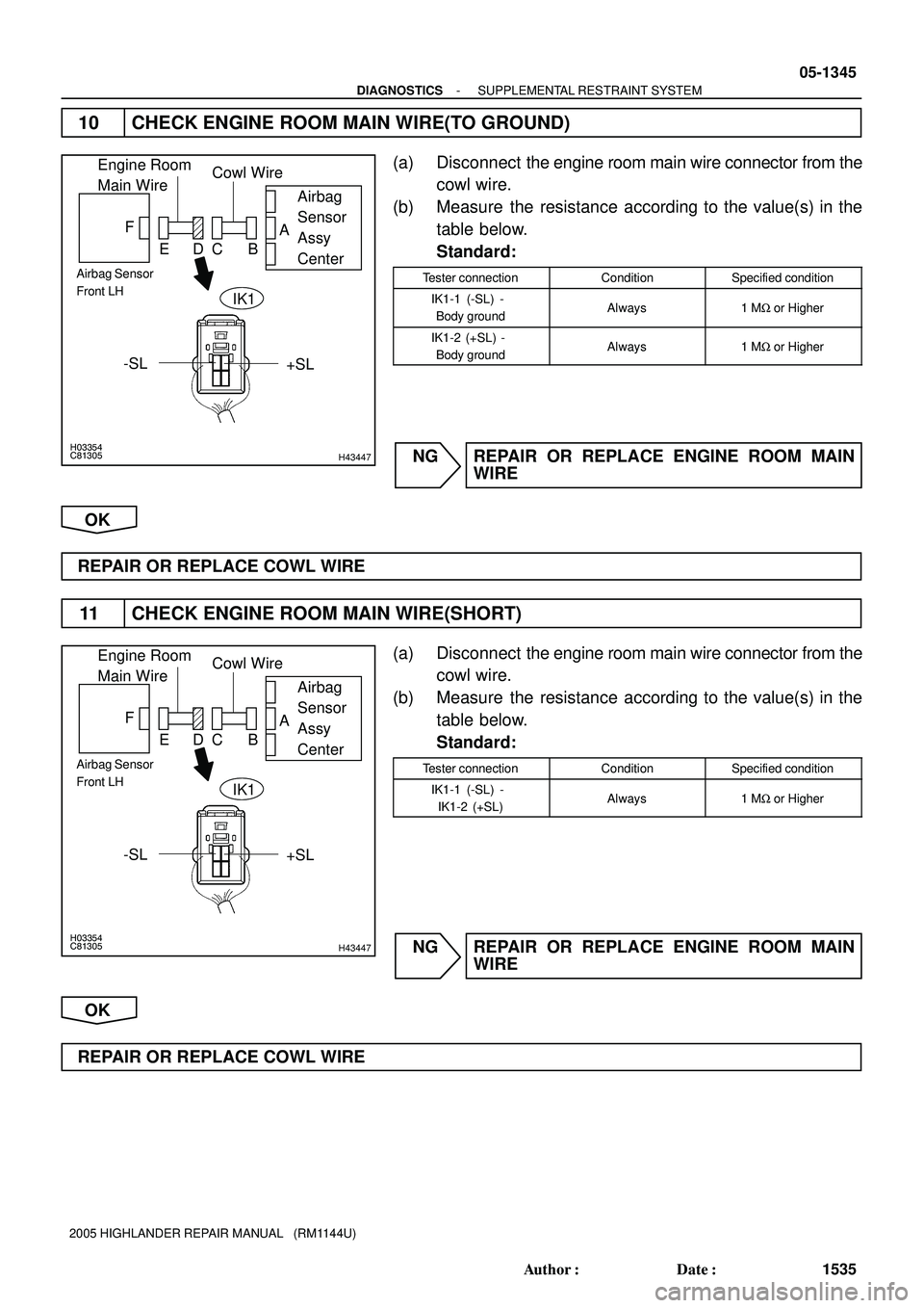
10 CHECK ENGINE ROOM MAIN WIRE(TO GROUND)
(a) Disconnect the engine room main wire connector from the
cowl wire.
(b) Measure the resistance according to the value(s) in the
table below.
Standard:
Tester connectionConditionSpecified condition
IK1-1 (-SL) -
Body groundAlways1 MW or Higher
IK1-2 (+SL) -
Body groundAlways1 MW or Higher
NG REPAIR OR REPLACE ENGINE ROOM MAIN
WIRE
OK
REPAIR OR REPLACE COWL WIRE
11 CHECK ENGINE ROOM MAIN WIRE(SHORT)
(a) Disconnect the engine room main wire connector from the
cowl wire.
(b) Measure the resistance according to the value(s) in the
table below.
Standard:
Tester connectionConditionSpecified condition
IK1-1 (-SL) -
IK1-2 (+SL)Always1 MW or Higher
NG REPAIR OR REPLACE ENGINE ROOM MAIN
WIRE
OK
REPAIR OR REPLACE COWL WIRE
Page 1129 of 2572
H43055H44105
Airbag Sensor Assy Center Occupant Classification ECU
FSR+
FSR- 8
B O6
BL14 BL11
A183
A1810
B W W
4
O6 FSR+
FSR-A18
A181
2(*1)
(*1) (*2)
(*2)
*1: w/ Curtain Shield Airbag
*2: w/o Curtain Shield Airbag 05-1346
- DIAGNOSTICSSUPPLEMENTAL RESTRAINT SYSTEM
1536 Author�: Date�:
2005 HIGHLANDER REPAIR MANUAL (RM1144U)
DTC B1150/23 OCCUPANT CLASSIFICATION SYSTEM
MALFUNCTION
CIRCUIT DESCRIPTION
The occupant classification system circuit consists of the airbag sensor assy center and the occupant classi-
fication system.
DTC B1150/23 is recorded when a malfunction is detected in the occupant classification system circuit.
DTC No.DTC Detecting ConditionTrouble Area
B1150/23�Occupant classification system malfunction
�Floor wire
�Front seat wire RH
�Occupant classification ECU
�Airbag sensor assy center
WIRING DIAGRAM
05IVP-03
Page 1130 of 2572
H02757H10600H44090H44098H44535
Occupant
Classification ECUAirbag
Sensor
Assy
Center
DTC B1150/23
DLC3
CG TC
- DIAGNOSTICSSUPPLEMENTAL RESTRAINT SYSTEM
05-1347
1537 Author�: Date�:
2005 HIGHLANDER REPAIR MANUAL (RM1144U)
INSPECTION PROCEDURE
1 CHECK DTC(OCCUPANT CLASSIFICATION ECU)
(a) Turn the ignition switch to the ON position, and wait for at least 10 seconds.
(b) Using the hand-held tester, check the DTCs of the occupant classification ECU (see page 05-1215).
OK:
DTC is not output.
NG GO TO INSPECTION PROCEDURE OF DTC
OUTPUT
OK
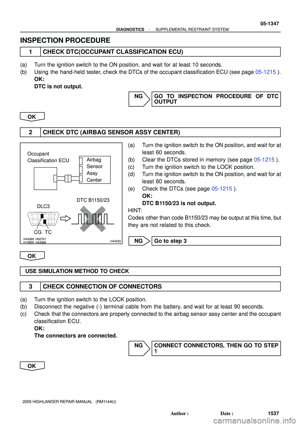
2 CHECK DTC (AIRBAG SENSOR ASSY CENTER)
(a) Turn the ignition switch to the ON position, and wait for at
least 60 seconds.
(b) Clear the DTCs stored in memory (see page 05-1215).
(c) Turn the ignition switch to the LOCK position.
(d) Turn the ignition switch to the ON position, and wait for at
least 60 seconds.
(e) Check the DTCs (see page 05-1215).
OK:
DTC B1150/23 is not output.
HINT:
Codes other than code B1150/23 may be output at this time, but
they are not related to this check.
NG Go to step 3
OK
USE SIMULATION METHOD TO CHECK
3 CHECK CONNECTION OF CONNECTORS
(a) Turn the ignition switch to the LOCK position.
(b) Disconnect the negative (-) terminal cable from the battery, and wait for at least 90 seconds.
(c) Check that the connectors are properly connected to the airbag sensor assy center and the occupant
classification ECU.
OK:
The connectors are connected.
NG CONNECT CONNECTORS, THEN GO TO STEP
1
OK
Page 1131 of 2572
H41715H44130 H44536H43694H44681
Occupant
Classification ECUAirbag
Sensor
Assy
Center
FSR+ F
CBA
ED
FSR-
FSR-FSR+
Service Wire
O6
A18 A18
(*1) (*2) FSR-
FSR+
*1: w/ Side and Curtain Shield Airbag
*2: w/o Side and Curtain Shield Airbag
H41715H44130H44536
Occupant
Classification ECU
FAirbag
Sensor
Assy
Center A
FSR-
FSR+ EDCB
A18
FSR-FSR+
A18
w/ Side and Curtain
Shield Airbagw/o Side and Curtain
Shield Airbag
05-1348
- DIAGNOSTICSSUPPLEMENTAL RESTRAINT SYSTEM
1538 Author�: Date�:
2005 HIGHLANDER REPAIR MANUAL (RM1144U)
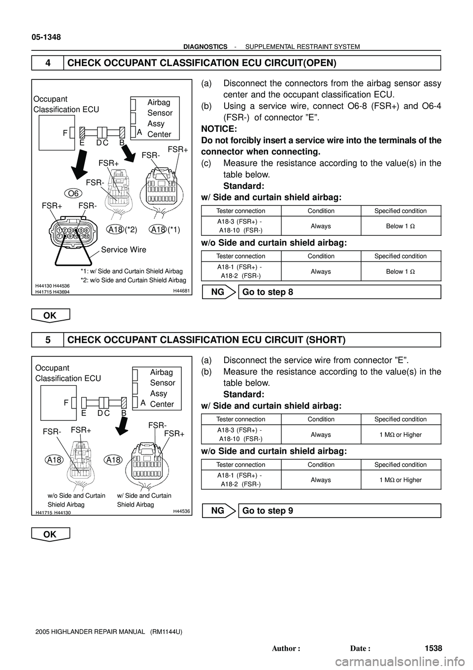
4 CHECK OCCUPANT CLASSIFICATION ECU CIRCUIT(OPEN)
(a) Disconnect the connectors from the airbag sensor assy
center and the occupant classification ECU.
(b) Using a service wire, connect O6-8 (FSR+) and O6-4
(FSR-) of connector ºEº.
NOTICE:
Do not forcibly insert a service wire into the terminals of the
connector when connecting.
(c) Measure the resistance according to the value(s) in the
table below.
Standard:
w/ Side and curtain shield airbag:
Tester connectionConditionSpecified condition
A18-3 (FSR+) -
A18-10 (FSR-)AlwaysBelow 1 W
w/o Side and curtain shield airbag:
Tester connectionConditionSpecified condition
A18-1 (FSR+) -
A18-2 (FSR-)AlwaysBelow 1 W
NG Go to step 8
OK
5 CHECK OCCUPANT CLASSIFICATION ECU CIRCUIT (SHORT)
(a) Disconnect the service wire from connector ºEº.
(b) Measure the resistance according to the value(s) in the
table below.
Standard:
w/ Side and curtain shield airbag:
Tester connectionConditionSpecified condition
A18-3 (FSR+) -
A18-10 (FSR-)Always1 MW or Higher
w/o Side and curtain shield airbag:
Tester connectionConditionSpecified condition
A18-1 (FSR+) -
A18-2 (FSR-)Always1 MW or Higher
NG Go to step 9
OK
Page 1132 of 2572
H41715H44130H44536
Occupant
Classification ECU
FAirbag
Sensor
Assy
Center A
FSR-
FSR+ EDCB
A18
FSR-FSR+
A18
w/ Side and Curtain
Shield Airbagw/o Side and Curtain
Shield Airbag
H41715H44130H44536
Occupant
Classification ECU
FAirbag
Sensor
Assy
Center A
FSR-
FSR+ EDCB
A18
FSR-FSR+
A18
w/ Side and Curtain
Shield Airbagw/o Side and Curtain
Shield Airbag
- DIAGNOSTICSSUPPLEMENTAL RESTRAINT SYSTEM
05-1349
1539 Author�: Date�:
2005 HIGHLANDER REPAIR MANUAL (RM1144U)
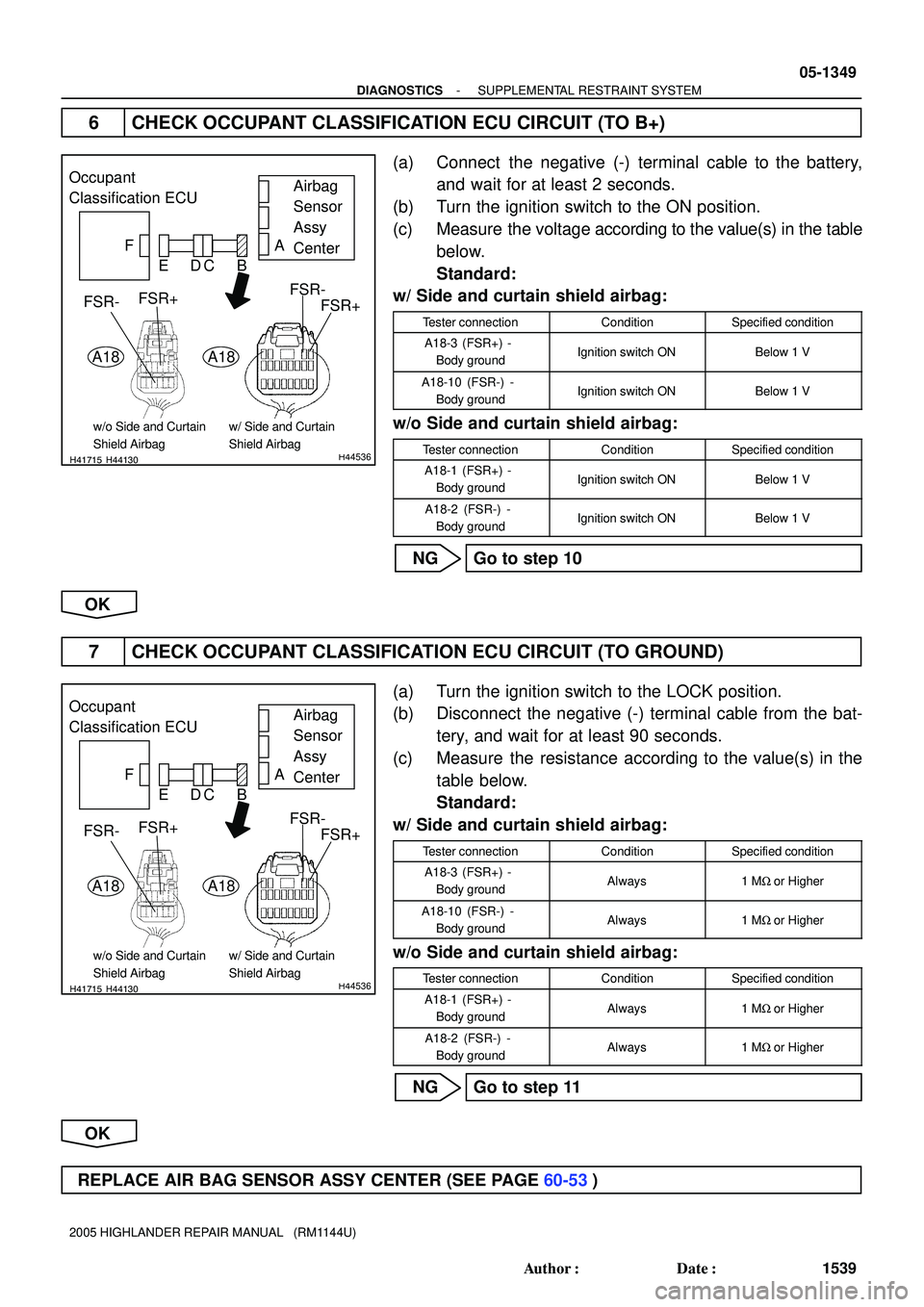
6 CHECK OCCUPANT CLASSIFICATION ECU CIRCUIT (TO B+)
(a) Connect the negative (-) terminal cable to the battery,
and wait for at least 2 seconds.
(b) Turn the ignition switch to the ON position.
(c) Measure the voltage according to the value(s) in the table
below.
Standard:
w/ Side and curtain shield airbag:
Tester connectionConditionSpecified condition
A18-3 (FSR+) -
Body groundIgnition switch ONBelow 1 V
A18-10 (FSR-) -
Body groundIgnition switch ONBelow 1 V
w/o Side and curtain shield airbag:
Tester connectionConditionSpecified condition
A18-1 (FSR+) -
Body groundIgnition switch ONBelow 1 V
A18-2 (FSR-) -
Body groundIgnition switch ONBelow 1 V
NG Go to step 10
OK
7 CHECK OCCUPANT CLASSIFICATION ECU CIRCUIT (TO GROUND)
(a) Turn the ignition switch to the LOCK position.
(b) Disconnect the negative (-) terminal cable from the bat-
tery, and wait for at least 90 seconds.
(c) Measure the resistance according to the value(s) in the
table below.
Standard:
w/ Side and curtain shield airbag:
Tester connectionConditionSpecified condition
A18-3 (FSR+) -
Body groundAlways1 MW or Higher
A18-10 (FSR-) -
Body groundAlways1 MW or Higher
w/o Side and curtain shield airbag:
Tester connectionConditionSpecified condition
A18-1 (FSR+) -
Body groundAlways1 MW or Higher
A18-2 (FSR-) -
Body groundAlways1 MW or Higher
NG Go to step 11
OK
REPLACE AIR BAG SENSOR ASSY CENTER (SEE PAGE 60-53)
Page 1133 of 2572
H03354H43116 H43129H44538
Occupant
Classification
ECUFront Seat
Wire RHFloor Wire
Airbag
Sensor
Assy
Center A
B C D E F
FSR-
FSR+
FSR+
FSR-
O6BL1
Service Wire
H03354H43116H03354H43116H43129
Occupant
Classification
ECUFront Seat
Wire RHFloor Wire
Airbag
Sensor
Assy
Center A
B C D E F
FSR-
FSR+
BL1
05-1350
- DIAGNOSTICSSUPPLEMENTAL RESTRAINT SYSTEM
1540 Author�: Date�:
2005 HIGHLANDER REPAIR MANUAL (RM1144U)
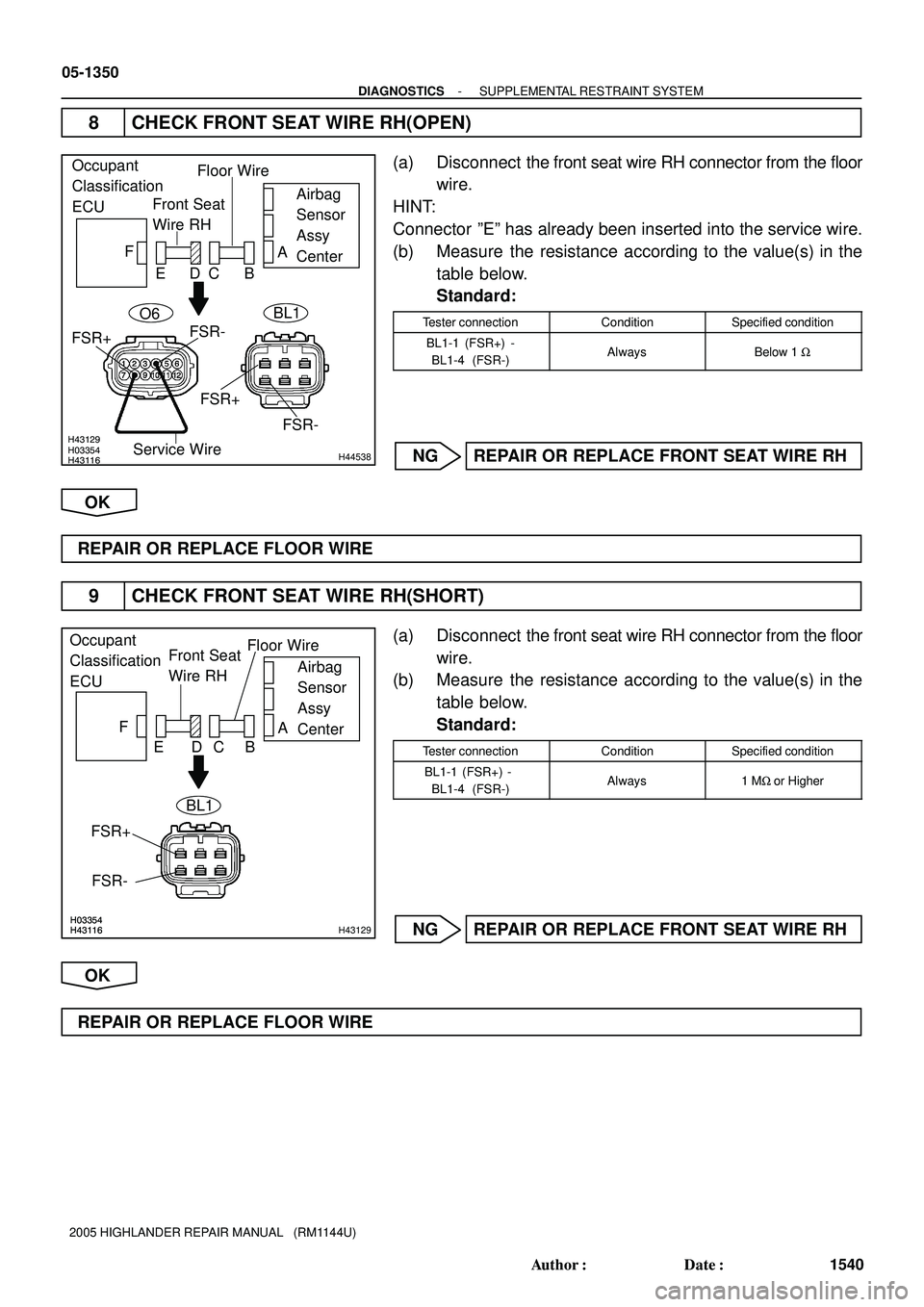
8 CHECK FRONT SEAT WIRE RH(OPEN)
(a) Disconnect the front seat wire RH connector from the floor
wire.
HINT:
Connector ºEº has already been inserted into the service wire.
(b) Measure the resistance according to the value(s) in the
table below.
Standard:
Tester connectionConditionSpecified condition
BL1-1 (FSR+) -
BL1-4 (FSR-)AlwaysBelow 1 W
NG REPAIR OR REPLACE FRONT SEAT WIRE RH
OK
REPAIR OR REPLACE FLOOR WIRE
9 CHECK FRONT SEAT WIRE RH(SHORT)
(a) Disconnect the front seat wire RH connector from the floor
wire.
(b) Measure the resistance according to the value(s) in the
table below.
Standard:
Tester connectionConditionSpecified condition
BL1-1 (FSR+) -
BL1-4 (FSR-)Always1 MW or Higher
NG REPAIR OR REPLACE FRONT SEAT WIRE RH
OK
REPAIR OR REPLACE FLOOR WIRE
Page 1134 of 2572
H03354H43116H03354H43116H43129
Occupant
Classification
ECUFront Seat
Wire RHFloor Wire
Airbag
Sensor
Assy
Center A
B C D E F
FSR-
FSR+
BL1
H03354H43116H03354H43116H43129
Occupant
Classification
ECUFront Seat
Wire RHFloor Wire
Airbag
Sensor
Assy
Center A
B C D E F
FSR-
FSR+
BL1
- DIAGNOSTICSSUPPLEMENTAL RESTRAINT SYSTEM
05-1351
1541 Author�: Date�:
2005 HIGHLANDER REPAIR MANUAL (RM1144U)
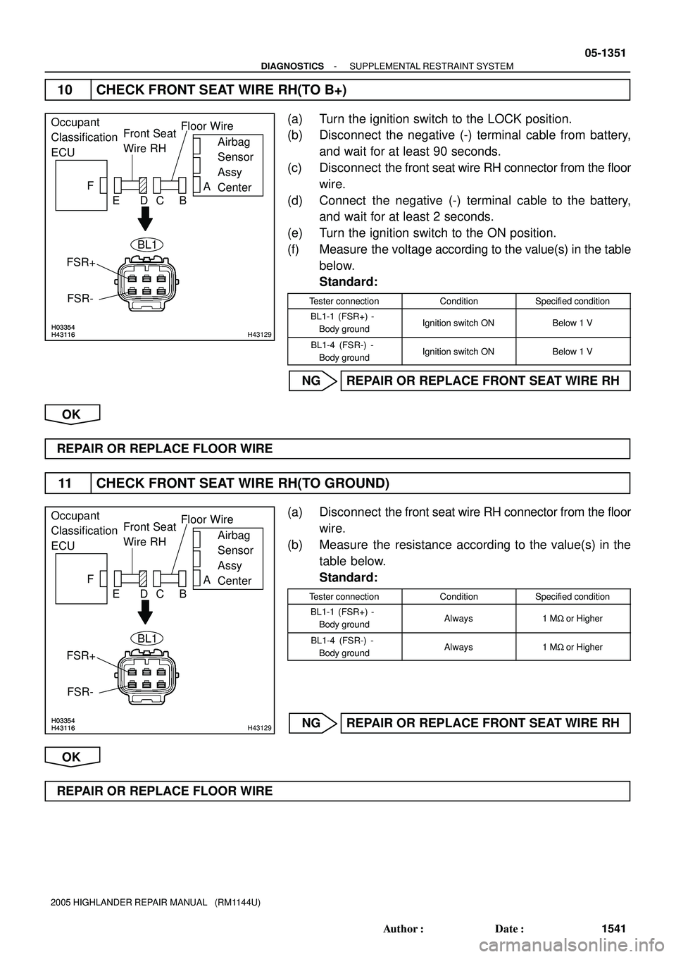
10 CHECK FRONT SEAT WIRE RH(TO B+)
(a) Turn the ignition switch to the LOCK position.
(b) Disconnect the negative (-) terminal cable from battery,
and wait for at least 90 seconds.
(c) Disconnect the front seat wire RH connector from the floor
wire.
(d) Connect the negative (-) terminal cable to the battery,
and wait for at least 2 seconds.
(e) Turn the ignition switch to the ON position.
(f) Measure the voltage according to the value(s) in the table
below.
Standard:
Tester connectionConditionSpecified condition
BL1-1 (FSR+) -
Body groundIgnition switch ONBelow 1 V
BL1-4 (FSR-) -
Body groundIgnition switch ONBelow 1 V
NG REPAIR OR REPLACE FRONT SEAT WIRE RH
OK
REPAIR OR REPLACE FLOOR WIRE
11 CHECK FRONT SEAT WIRE RH(TO GROUND)
(a) Disconnect the front seat wire RH connector from the floor
wire.
(b) Measure the resistance according to the value(s) in the
table below.
Standard:
Tester connectionConditionSpecified condition
BL1-1 (FSR+) -
Body groundAlways1 MW or Higher
BL1-4 (FSR-) -
Body groundAlways1 MW or Higher
NG REPAIR OR REPLACE FRONT SEAT WIRE RH
OK
REPAIR OR REPLACE FLOOR WIRE
Page 1135 of 2572
05-1352
- DIAGNOSTICSSUPPLEMENTAL RESTRAINT SYSTEM
1542 Author�: Date�:
2005 HIGHLANDER REPAIR MANUAL (RM1144U)
DTC B1152/28 PASSENGER AIRBAG ON/OFF INDICATOR
LIGHT CIRCUIT MALFUNCTION
CIRCUIT DESCRIPTION
The passenger airbag ON/OFF indicator light circuit consists of the airbag sensor assy center and the telltale
lamp assy (passenger airbag ON/OFF indicator).
This circuit indicates the operation condition of the front passenger airbag assy and the front seat airbag assy
RH and passenger side seat belt pretensioner.
DTC B1152/28 is recorded when a malfunction is detected in the passenger airbag ON/OFF indicator light
circuit.
DTC No.DTC Detecting ConditionTrouble Area
B1152/28
�When the airbag sensor assy center receives a line short
signal, open signal, short to ground signal or B+ short
signal in the passenger airbag ON/OFF indicator light cir-
cuit for 2 seconds.
�Telltale lamp assy malfunction
�Airbag sensor assy center malfunction
�Telltale lamp (Passenger airbag ON/OFF indicator)
�Airbag sensor assy center
�Cowl wire
05IVQ-02