Page 939 of 1897

(e) Check whether there is misfire or not by monitoring DTC and the freeze frame data. After that, record
them.
(f) Turn the igniti")
DI-60
- DIAGNOSTICSENGINE
216 Author�: Date�:
2001 AVALON (RM808U)
(e) Check whether there is misfire or not by monitoring DTC and the freeze frame data. After that, record
them.
(f) Turn the ignition switch OFF and wait at least 5 seconds.
INSPECTION PROCEDURE
HINT:
�If is case that DTC besides misfire is memorized simultaneously, first perform the troubleshooting for
them.
�Read freeze frame data using TOYOTA hand-held tester or OBD II scan tool. Because freeze frame
data records the engine conditions when the malfunction is detected. When troubleshooting, it is useful
for determining whether the vehicle was running or stopped, the engine was warmed up or not, the
air-fuel ratio was lean or rich, etc. at the time of the malfunction.
�When the vehicle is brought to the workshop and the misfire is not occurred, misfire can be confirmed
by reproducing the condition or freeze frame data. Also, after finishing the repair, confirm that there
is no misfire. (See the confirmation driving pattern)
�When either of SHORT FT #1, LONG FT #1, SHORT FT #2 or LONG FT #2 in the freeze frame data
is besides the range of ±20 %, there is a possibility that the air-fuel ratio is inclining either to ºrichº (-20
% or less) or ºleanº (+20 % or more).
�When COOLANT TEMP in the freeze frame data is less than 80°C (176°F), there is a possibility or
misfire only during warming up.
�In the case that misfire cannot be reproduced, the reason may be because of the driving with lack or
fuel, the use of improper fuel, a stain of ignition plug, and etc.
1 Check wire harness, connector and vacuum hose in engine room.
CHECK:
(a) Check the connection conditions of wire harness and connector.
(b) Check the disconnection, piping and break of vacuum hose.
NG Repair or replace, then confirm that there is no
misfire (See the confirmation driving pattern).
OK
Page 940 of 1897

#50 #60#30
(-)
- DIAGNOSTICSENGINE
DI-61
217 Author�: Date�:
2001 AVALON (RM808U)
2 Check spark plug and spark of misfiring cylinder.
PREPARATION")
B02101B04941
A06102
1.1 mm
A02024
ON
#10
#20 #40
(+)
#50 #60#30
(-)
- DIAGNOSTICSENGINE
DI-61
217 Author�: Date�:
2001 AVALON (RM808U)
2 Check spark plug and spark of misfiring cylinder.
PREPARATION:
(a) Remove the ignition coil (See page IG-5).
(b) Remove the spark plug.
CHECK:
(a) Check spark plug type.
(b) Check the electrode for carbon deposits.
(c) Check electrode gap.
OK:
(a) Iridium-tipped spark plug
Recommended spark plug:
DENSO made: SK20R11
NGK made: IFR6A11
(b) No large carbon deposit present.
Not wet with gasoline or oil.
(c) Electrode gap: 1.1 mm (0.043 in.)
PREPARATION:
(a) Install the spark plug to the ignition coil, and connect the
ignition coil connector.
(b) Disconnect the injector connector.
(c) Ground the spark plug.
CHECK:
Check if spark occurs while engine is being cranked.
OK:
Spark jumps across electrode gap.
NG Replace or check ignition system (See page
IG-1).
OK
3 Check voltage of ECM terminal for injector of failed cylinder.
PREPARATION:
(a) Remove the glove compartment (See page SF-82).
(b) Turn the ignition switch ON.
CHECK:
Measure the voltage between applicable terminal of the ECM
connector and body ground.
OK:
Voltage: 9 - 14 V
Page 941 of 1897
FI6588
FI6538
A00064
10 V
/Division10 V
/Division
GND GND
100 msec./Division (Idling)1 msec./Division (Idling)
Injection duration
(Magnification) Injector Signal Waveform
DI-62
- DIAGNOSTICSENGINE
218 Author�: Date�:
2001 AVALON (RM808U)
Reference: INSPECTION USING OSCILLOSCOPE
With the engine idling, check the waveform between terminals #10 - #60 and E01 of the ECM connector.
HINT:
The correct waveform is as shown.
OK Go to step 5.
NG
4 Check resistance of injector of misfiring cylinder (See page SF-19).
NG Replace injector.
OK
Check for open and short in harness and con-
nector between injector and ECM (See page
IN-30).
5 Check fuel pressure (See page SF-6).
NG Check and repair fuel pump, fuel pipe line and
filter (See page SF-1).
Page 942 of 1897
- DIAGNOSTICSENGINE
DI-63
219 Author�: Date�:
2001 AVALON (RM808U)
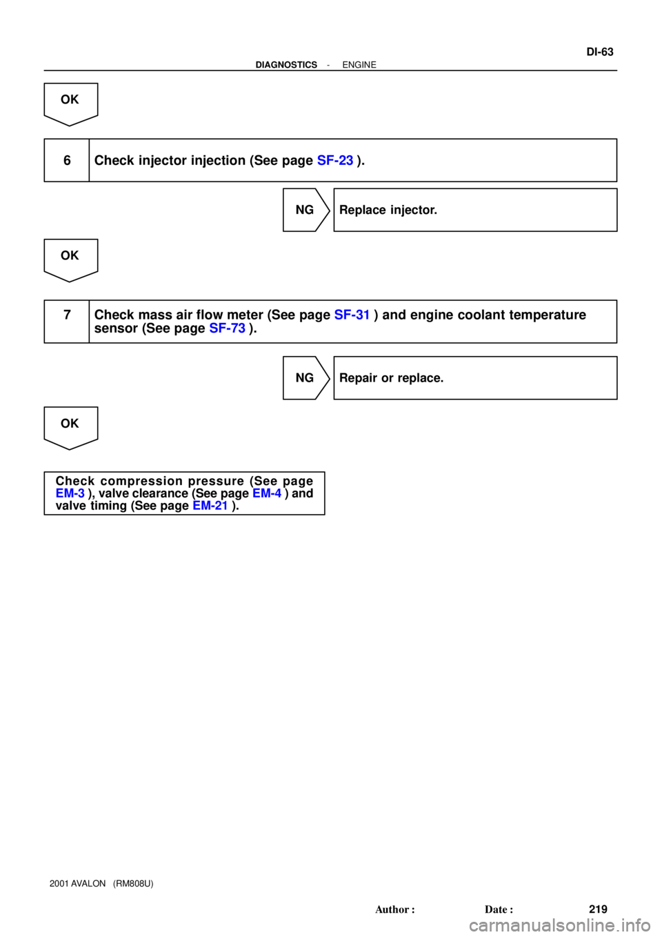
OK
6 Check injector injection (See page SF-23).
NG Replace injector.
OK
7 Check mass air flow meter (See page SF-31) and engine coolant temperature
sensor (See page SF-73).
NG Repair or replace.
OK
Check compression pressure (See page
EM-3), valve clearance (See page EM-4) and
valve timing (See page EM-21).
Page 944 of 1897

A00304
Knock SensorECM
EB1
Male
ConnectorFemale
Connector 1
111
22KNKR
KNKL
EB1
E4
E427
28
FI7050
S06024
S06025
FI6510FI6607A00113
KNK Signal Waveform
0.5 V
/Division
5 msec./Division
100 msec./Division 0V
200 mV
/Division
0V
- DIAGNOSTICSENGINE
DI-65
221 Author�: Date�:
2001 AVALON (RM808U)
�Read freeze frame data using TOYOTA hand-held tester or OBD II scan tool. Because freeze frame
records the engine conditions when the malfunction is detected. When troubleshooting, it is useful for
determining whether the vehicle was running or stopped, the engine was warmed up or not, the air-fuel
ratio was lean or rich, etc. at the time of the malfunction.
1 Connect OBD II scan tool or TOYOTA hand-held tester, and check knock sensor
circuit.
PREPARATION:
(a) Connect the OBD II scan tool or TOYOTA hand-held tes-
ter to the DLC3.
(b) Disconnect the wire from wire connector EB1.
(c) Connect the terminals of the disconnected EB1 male con-
nector and EB1 female as follows.
Male connector eFemale connector
Terminal 1 e Terminal 2
Terminal 2 e Terminal 1
(d) Turn the ignition switch ON and push the OBD II scan tool
or TOYOTA hand-held tester main switch ON.
(e) After the engine is warmed up, perform quick racing to
4,000 rpm 3 times.
CHECK:
Check the DTC.
RESULT:
Type IDTC same as when vehicle brought in
P0325 " P0325 or P0330 " P0330
Type IIDTC different to when vehicle brought in
P0325 " P0330 or P0330 " P0325
Reference: INSPECTION USING OSCILLOSCOPE
�With the engine racing (4,000 rpm), check the waveform
between terminals KNKR, KNKL of the ECM connector
and body ground.
HINT:
The correct waveform is as shown.
�Spread the time on the horizontal axis, and confirm that
period of the wave is 141 msec. (Normal mode vibration
frequency of knock sensor: 7.1 kHz)
HINT:
If normal mode vibration frequency is not 7.1 kHz, the sensor
is malfunctioning.
Type II Go to step 3.
Page 945 of 1897
DI-66
- DIAGNOSTICSENGINE
222 Author�: Date�:
2001 AVALON (RM808U)
Type I
2 Check for open and short in harness and connector between EB1 connector and
ECM (See page IN-30).
NG Repair or replace harness or connector.
OK
Check and replace ECM (See page IN-30).
3 Check for open and short in harness and connector between EB1 connector and
knock sensor (See page IN-30).
HINT:
�If DTC P0325 has changed to P0330, check the knock sensor circuit on the right bank side.
�If DTC P0330 has changed to P0325, check the knock sensor circuit on the left bank side.
NG Repair or replace harness or connector.
OK
Replace knock sensor.
Page 947 of 1897
A11663
VV1, VV2 and NE Signal Waveforms2 V
/Division
20 msec./Division (Idling)
VV1
NE VV2GND
GND
GND
DI-68
- DIAGNOSTICSENGINE
224 Author�: Date�:
2001 AVALON (RM808U)
1 Check resistance of crankshaft position sensor (See page IG-9).
Reference: INSPECTION USING OSCILLOSCOPE
During cranking or idling, check the waveforms between termi-
nals VV1 and NE-, VV2 and NE-, and NE and NE- of the ECM
connectors.
HINT:
The correct waveforms are as shown.
NG Replace crankshaft position sensor.
OK
2 Check for open and short in harness and connector between ECM and crank-
shaft position sensor (See page IN-30).
NG Repair or replace harness or connector.
OK
3 Inspect sensor installation and signal plate teeth of crankshaft timing pulley.
NG Tighten sensor. Replace crankshaft timing
pulley.
OK
Check and replace ECM (See page IN-30).
Page 948 of 1897

DTC P0340 Camshaft Position Sensor Circuit Malfunc-
tion
CIRCUIT DESCRIPTION
Camshaft position sensor (G (VV) signal) consists of a")
- DIAGNOSTICSENGINE
DI-69
225 Author�: Date�:
2001 AVALON (RM808U)
DTC P0340 Camshaft Position Sensor Circuit Malfunc-
tion
CIRCUIT DESCRIPTION
Camshaft position sensor (G (VV) signal) consists of a magnet, iron core and pickup coil.
The G (VV) signal plate has 3 teeth, on its outer circumference and is installed the camshaft timing gear.
When the camshafts rotate, the protrusion on the signal plate and the air gap on the pickup coil change,
causing fluctuations in the magnetic field and generating an electromotive force in the pickup coil.
The NE signal plate has 34 teeth and is installed the crankshaft timing pulley. The NE signal sensor gener-
ates 34 signals at every engine revolution. The ECM detects the standard crankshaft angle based on the
G (VV) signal and the actual crankshaft angle and the engine speed by the NE signal.
DTC No.DTC Detecting ConditionTrouble Area
P0340
No camshaft position sensor signal to ECM during cranking (2
trip detection logic)�Open or short in camshaft position sensor circuit
�Camshaft position sensor
P0340No camshaft position sensor signal to ECM with engine speed
600 rpm or more
�Camshaft osition sensor
�Camshaft timing gear
�ECM
WIRING DIAGRAM
Refer to DTC P0335 on page DI-67.
INSPECTION PROCEDURE
HINT:
Read freeze frame data using TOYOTA hand-held tester or OBD II scan tool. Because freeze frame records
the engine conditions when the malfunction is detected. When troubleshooting, it is useful for determining
whether the vehicle was running or stopped, the engine was warmed up or not, the air-fuel ratio was lean
or rich, etc. at the time of the malfunction.
1 Check resistance of camshaft position sensor (See page IG-1).
Reference: INSPECTION USING OSCILLOSCOPE
Refer to DTC P0335 on page DI-67.
NG Replace camshaft position sensor.
OK
2 Check for open and short in harness and connector between ECM and camshaft
position sensor (See page IN-30).
NG Repair or replace harness or connector.
DI07V-09
1 msec./Division (Idling)
Injection duration
(Magnification) Injector Signal Waveform
DI-62
- DIAGNOSTICSENGINE
218")