Page 1778 of 1897

or less
- STEERINGPOWER STEERING FLUID
SR-5
1468 Author�: Date�:
2001 AVALON (RM808U)
INSPECTION
1.")
R11740
HOT
COLD
SR0EF-04
R11741
Normal Abnormal
R11786Engine Idling
Engine Stopped 5 mm (0.20 in.)
or less
- STEERINGPOWER STEERING FLUID
SR-5
1468 Author�: Date�:
2001 AVALON (RM808U)
INSPECTION
1. CHECK FLUID LEVEL
(a) Keep the vehicle level.
(b) With the engine stopped, check the fluid level in the oil
reservoir.
If necessary, add fluid.
Fluid: ATF DEXRON® II or III
HINT:
Check that the fluid level is within the HOT LEVEL range on the
reservoir. If the fluid is cold, check that it is within the COLD
LEVEL range.
(c) Start the engine and run it at idle.
(d) Turn the steering wheel from lock to lock several times to
boost fluid temperature.
Fluid temperature: 80°C (176°F)
(e) Check for foaming or emulsification.
If there is foaming or emulsification, bleed power steering sys-
tem (See page SR-4).
(f) With the engine idling, measure the fluid level in the oil
reservoir.
(g) Stop the engine.
(h) Wait a few minutes and remeasure the fluid level in the oil
reservoir.
Maximum fluid level rise: 5 mm (0.20 in.)
If a problem is found, bleed power steering system (See page
SR-4).
(i) Check the fluid level.
Page 1779 of 1897
R14662
Attachment
IN
OUT Pressure Feed Tube SST
Z15498
Oil
Reservoir
PS Vane
Pump PS Gear
SST Closed SR-6
- STEERINGPOWER STEERING FLUID
1469 Author�: Date�:
2001 AVALON (RM808U)
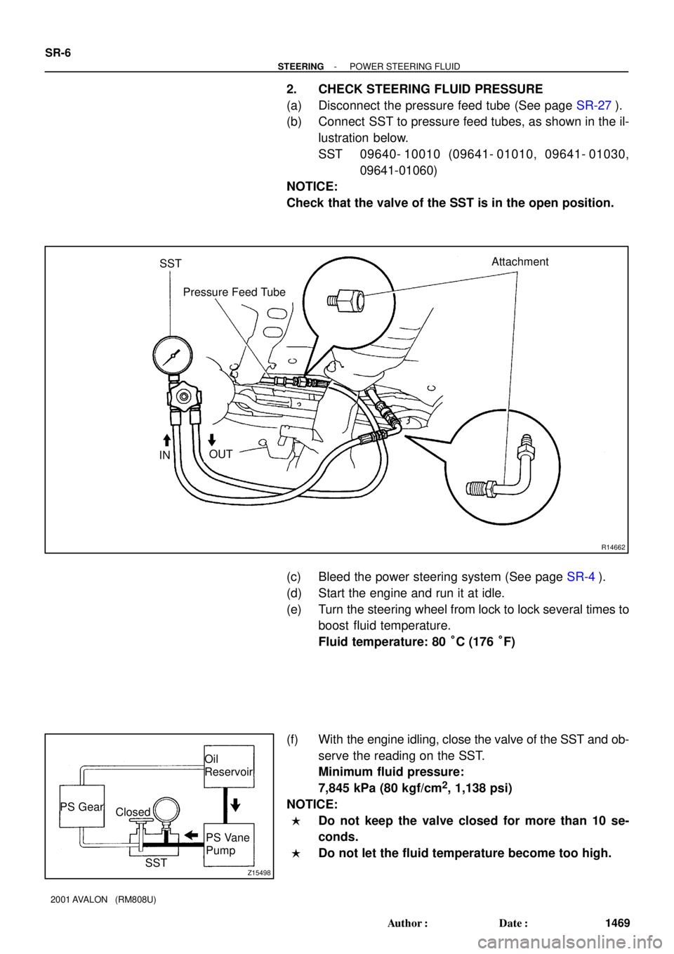
2. CHECK STEERING FLUID PRESSURE
(a) Disconnect the pressure feed tube (See page SR-27).
(b) Connect SST to pressure feed tubes, as shown in the il-
lustration below.
SST 09640- 10010 (09641- 01010, 09641- 01030,
09641-01060)
NOTICE:
Check that the valve of the SST is in the open position.
(c) Bleed the power steering system (See page SR-4).
(d) Start the engine and run it at idle.
(e) Turn the steering wheel from lock to lock several times to
boost fluid temperature.
Fluid temperature: 80 °C (176 °F)
(f) With the engine idling, close the valve of the SST and ob-
serve the reading on the SST.
Minimum fluid pressure:
7,845 kPa (80 kgf/cm
2, 1,138 psi)
NOTICE:
�Do not keep the valve closed for more than 10 se-
conds.
�Do not let the fluid temperature become too high.
Page 1815 of 1897
F08857
SR0EG-05
F08858
SR-8
- STEERINGSTEERING WHEEL
1471 Author�: Date�:
2001 AVALON (RM808U)
STEERING WHEEL
INSPECTION
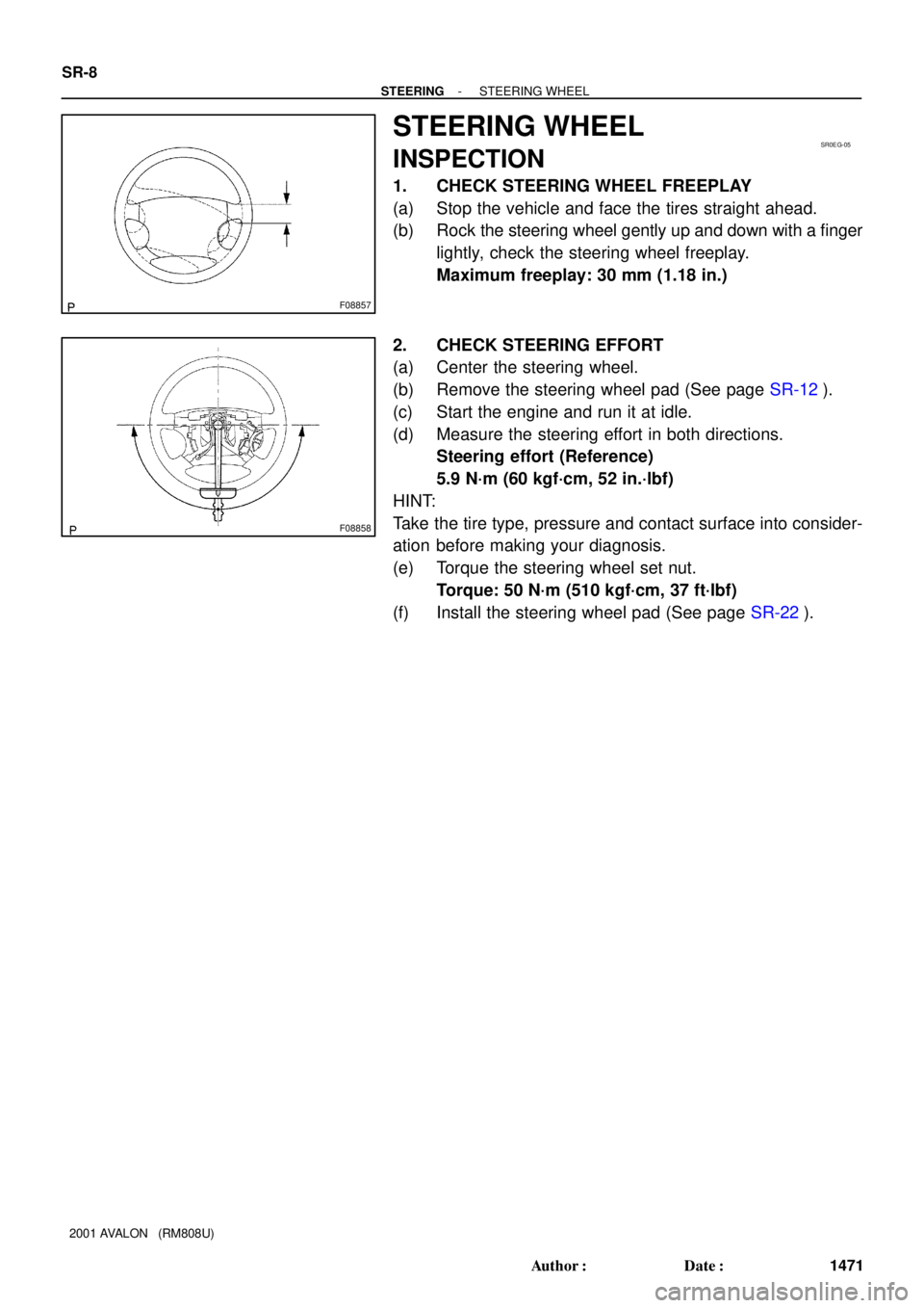
1. CHECK STEERING WHEEL FREEPLAY
(a) Stop the vehicle and face the tires straight ahead.
(b) Rock the steering wheel gently up and down with a finger
lightly, check the steering wheel freeplay.
Maximum freeplay: 30 mm (1.18 in.)
2. CHECK STEERING EFFORT
(a) Center the steering wheel.
(b) Remove the steering wheel pad (See page SR-12).
(c) Start the engine and run it at idle.
(d) Measure the steering effort in both directions.
Steering effort (Reference)
5.9 N´m (60 kgf´cm, 52 in.´lbf)
HINT:
Take the tire type, pressure and contact surface into consider-
ation before making your diagnosis.
(e) Torque the steering wheel set nut.
Torque: 50 N´m (510 kgf´cm, 37 ft´lbf)
(f) Install the steering wheel pad (See page SR-22).
Page 1822 of 1897

INSPECTION
1. INSPECT STEERING LOCK OPERATION
Check that the steering lock mechanism operates pr")
SR0Z6-01
F09913
F09914
SR-18
- STEERINGTILT STEERING COLUMN
1481 Author�: Date�:
2001 AVALON (RM808U)
INSPECTION
1. INSPECT STEERING LOCK OPERATION
Check that the steering lock mechanism operates properly.
2. IF NECESSARY, REPLACE KEY CYLINDER
(a) Place the ignition key at the ACC position.
(b) Push down the stop pin with a screwdriver, and pull out
the key cylinder.
(c) Install a new key cylinder.
HINT:
Make sure the ignition key is at the ACC position.
3. INSPECT IGNITION SWITCH (See page BE-16)
4. IF NECESSARY, REPLACE IGNITION SWITCH
(a) Remove the 2 screws and ignition switch.
(b) Install a new ignition switch with the 2 screws.
5. INSPECT KEY UNLOCK WARNING SWITCH
(See page BE-16)
6. IF NECESSARY, REPLACE KEY UNLOCK WARNING
SWITCH
(a) Slide the key unlock warning switch out of the column up-
per bracket.
(b) Slide a new key unlock warning switch in the column up-
per bracket.
7. INSPECT KEY INTERLOCK SOLENOID
(See page AX-16 and AX-18)
8. IF NECESSARY, REPLACE KEY INTERLOCK SOLE-
NOID
(a) Remove the 2 screws and key interlock solenoid.
(b) Install a new key interlock solenoid with the 2 screws.
9. Column shift:
INSPECT SHIFT LOCK SOLENOID, SHIFT LOCK
SWITCH AND SHIFT LOCK CONTROL ECU
(See page AX-18)
10. Column shift:
IF NECESSARY, REPLACE SHIFT LOCK SOLENOID,
SHIFT LOCK SWITCH AND SHIFT LOCK CONTROL
ECU
11. w/ Engine immobiliser system:
INSPECT TRANSPONDER KEY COIL
(See page BE-181)
12. w/ Engine immobiliser system:
IF NECESSARY, REPLACE TRANSPONDER KEY
COIL
Page 1823 of 1897
F09915
F09916
- STEERINGTILT STEERING COLUMN
SR-19
1482 Author�: Date�:
2001 AVALON (RM808U)
13. w/ Engine immobiliser system:
IF NECESSARY, REPLACE TRANSPONDER KEY AM-
PLIFIER
(a) Remove the 2 screws and transponder key amplifier.
(b) Install a new transponder key amplifier with the 2 screws.
14. INSPECT BEARING
Check the bearing rotation condition and check for abnormal
noise.
If faulty, replace the steering column upper tube sub-assembly.
15. INSPECT BUSHING
Check the bushing rotation condition and check for abnormal
noise.
If faulty, replace the steering column assembly.
Page 1837 of 1897

REMOVAL
1. REMOVE FRONT WHEEL
Torque: 103 N´m (1,050 kgf´cm, 76 ft´lbf)
2. CHECK")
SA0VS-02
W03084
W03093
W03139
- SUSPENSION AND AXLEFRONT AXLE HUB
SA-9
1343 Author�: Date�:
2001 AVALON (RM808U)
REMOVAL
1. REMOVE FRONT WHEEL
Torque: 103 N´m (1,050 kgf´cm, 76 ft´lbf)
2. CHECK BEARING BACKLASH AND AXLE HUB DEVI-
ATION
(a) Remove the 2 bolts, brake caliper and disc.
(b) Support the brake caliper securely.
(c) Using a dial indicator, check the backlash near the center
of the axle hub.
Maximum: 0.05 mm (0.0020 in.)
If the backlash exceeds the maximum, replace the bearing.
(d) Using a dial indicator, check the deviation at the surface
of the axle hub outside the hub bolt.
Maximum: 0.05 mm (0.0020 in.)
If the deviation exceeds the maximum, replace the axle hub.
(e) Install the disc, brake caliper and 2 bolts.
Torque: 107 N´m (1,090 kgf´cm, 79 ft´lbf)
3. REMOVE DRIVE SHAFT LOCK NUT
(a) Remove the cotter pin and lock cap.
(b) While applying the brakes, remove the nut.
Torque: 294 N´m (3,000 kgf´cm, 217 ft´lbf)
(c) Remove the 2 bolts, brake caliper and disc.
(d) Support the brake caliper securely.
4. DISCONNECT ABS SPEED SENSOR AND WIRE HAR-
NESS CLAMP
Remove the bolt and disconnect the ABS speed sensor and
wire harness clamp.
Torque: 8.0 N´m (82 kgf´cm, 71 in.´lbf)
5. LOOSEN 2 NUTS ON LOWER SIDE OF SHOCK AB-
SORBER
HINT:
Do not remove the bolts.
Torque: 211 N´m (2,150 kgf´cm, 156 ft´lbf)
HINT:
At the this time of installation, coat the nut's thread with engine
oil.
Page 1869 of 1897

F04031
F04048
1
2
F01195
Bolt
Adjusting
ValueSet Bolt
15'
30'Adjusting Bolt90105-17001 90105-17003 90105-17004 90105-17005
45'
1°00'
1°15'
1°30'121212121 Dot
2 Dots3 Dots
- SUSPENSION AND AXLEFRONT WHEEL ALIGNMENT
SA-5
1339 Author�: Date�:
2001 AVALON (RM808U)
4. ADJUST CAMBER
NOTICE:
After the camber has been adjusted, inspect the toe-in.
(a) Remove the front wheel and ABS speed sensor clamp.
(b) Remove the 2 nuts on the lower side of the shock absorb-
er.
(c) Coat the threads of the nuts with engine oil.
(d) Temporarily install the 2 nuts.
(e) Adjust the camber by pushing or pulling the lower side of
the shock absorber in the direction in which the camber
adjustment is required.
(f) Tighten the nuts.
Torque: 211 N´m (2,150 kgf´cm, 156 ft´lbf)
(g) Install the ABS speed sensor clamp and front wheel.
Torque: 103 N´m (1,050 kgf´cm, 76 ft´lbf)
(h) Check the camber.
HINT:
�Try to adjust the camber to the center of the specified val-
ue.
�Adjusting value for the set bolts is 6' - 30' (0.1° - 0.5°).
If the camber is not within the specified value, using the follow-
ing table, estimate how much additional camber adjustment will
be required, and select the camber adjusting bolt.
(i) Do the steps mentioned above again. Between step (b)
and (c), replace 1 or 2 selected bolts.
HINT:
When replacing the 2 bolts, replace 1 bolt for each time.