Page 917 of 1897

1 Connect OBD II scan tool or TOYOTA hand-held")
A00214
ON
Engine Coolant
Temp. Sensor
ECM
5V
E2 14
18 2
1
THW
BE6653
FI7055
E5 E5
- DIAGNOSTICSENGINE
DI-33
189 Author�: Date�:
2001 AVALON (RM808U)
1 Connect OBD II scan tool or TOYOTA hand-held tester, and read value of engine
coolant temperature.
PREPARATION:
(a) Connect the OBD II scan tool or TOYOTA hand-held tester to the DLC3.
(b) Turn the ignition switch ON and push the OBD II scan tool or TOYOTA hand-held tester main switch
ON.
CHECK:
Read the temperature value on the OBD II scan tool or TOYOTA hand-held tester.
OK:
Same as actual engine coolant temperature.
HINT:
�If there is open circuit, OBD II scan tool or TOYOTA hand-held tester indicates -40°C (-40°F).
�If there is short circuit, OBD II scan tool or TOYOTA hand-held tester indicates 140°C (284°F) or more.
NG -40°C (-40°F) ... Go to step 2.
140°C (284°F) or more ... Go to step 4.
OK
Check for intermittent problems
(See page DI-3).
2 Check for open in harness or ECM.
PREPARATION:
(a) Disconnect the engine coolant temp. sensor connector.
(b) Connect the sensor wire harness terminals together.
(c) Turn the ignition switch ON.
CHECK:
Read the temperature value on the OBD II scan tool or TOYO-
TA hand-held tester.
OK:
Temperature value: 1405C (2845F) or more
OK Confirm good connection at sensor. If OK, re-
place engine coolant temperature sensor.
NG
Page 918 of 1897

A02020
ON
Engine Coolant Temp. Sensor
E2
THWECM
5 V
E2 2
114
18 E5
E5THW
A00216
ON
Engine Coolant
Temp. Sensor
ECM
5 V
E2 14
18
E5
E5THW
FI7054 BE6653
DI-34
- DIAGNOSTICSENGINE
190 Author�: Date�:
2001 AVALON (RM808U)
3 Check for open in harness or ECM.
PREPARATION:
(a) Remove the glove compartment (See page SF-82).
(b) Connect between terminals THW and E2 of the ECM con-
nector.
HINT:
The engine coolant temperature sensor connector is discon-
nected. Before checking, do a visual and contact pressure
check for the ECM connector (See page IN-30).
(c) Turn the ignition switch ON.
CHECK:
Read the temperature value on the OBD II scan tool or TOYO-
TA hand-held tester.
OK:
Temperature value: 1405C (2845F) or more
OK Open in harness between terminal E2 or THW,
repair or replace harness.
NG
Confirm good connection at ECM. If OK,
check and replace ECM (See page IN-30).
4 Check for short in harness and ECM.
PREPARATION:
(a) Disconnect the engine coolant temperature sensor con-
nector.
(b) Turn the ignition switch ON.
CHECK:
Read the temperature value on the OBD II scan tool or TOYO-
TA hand-held tester.
OK:
Temperature value: -405C (-405F)
OK Replace engine coolant temperature sensor.
NG
Page 919 of 1897
A02043
ON
Engine Coolant Temp. SensorECM
5 V
E2 THW
E5 Connector
- DIAGNOSTICSENGINE
DI-35
191 Author�: Date�:
2001 AVALON (RM808U)
5 Check for short in harness or ECM.
PREPARATION:
(a) Remove the glove compartment (See page SF-82).
(b) Disconnect the E5 connector from the ECM.
HINT:
The engine coolant temperature sensor connector is discon-
nected.
(c) Turn the ignition switch ON.
CHECK:
Read the temperature value on the OBD II scan tool or TOYO-
TA hand-held tester.
OK:
Temperature value: -405C (-405F)
OK Repair or replace harness or connector.
NG
Check and replace ECM (See page IN-30).
Page 920 of 1897

DTC P0116 Engine Coolant Temp. Circuit Range/Perfor-
mance Problem
CIRCUIT DESCRIPTION
Refer to DTC P0115 on page DI-32.
DTC No.DTC")
DI-36
- DIAGNOSTICSENGINE
192 Author�: Date�:
2001 AVALON (RM808U)
DTC P0116 Engine Coolant Temp. Circuit Range/Perfor-
mance Problem
CIRCUIT DESCRIPTION
Refer to DTC P0115 on page DI-32.
DTC No.DTC Detecting ConditionTrouble Area
If THW -7°C (19.4°F), 20 min. or more after starting engine,
engine coolant temp. sensor value is 20°C (68°F) or less (2
trip detection logic)
If THW -7°C (19.4°F), and <10°C (50°F), 5 min. or more
after starting engine, engine coolant temp. sensor value is
20°C (95°F) or less (2 trip detection logic)
If THW 10°C (50°F), 2 min. or more after starting engine,
engine coolant temp. sensor value is 30°C (86°F) or less (2
trip detection logic)
�Cooling systemP0116When THW � 35°C (95°F) or more and less than 60°C
(140°F), and THA � - 6.7°C (19.9°F) or more, when starting
engine, conditions (a) and (b) continue: (2 trip detection logic)
(a) Vehicle speed is changing (Not stable)
(b) THW change is lower than 3°C (5.4°F) from THW since
when starting engine�Cooling system
�Engine coolant temp. sensor
In case that reading value of water temp. sensor will not
change more than 1°C (1.8°F) even after repeating 6 trips
(detection logic) of adjusting speed pattern with THW more
than 60°C (140°F) when engine starts.
INSPECTION PROCEDURE
HINT:
�If DTCs P0115 and P0116 are output simultaneously, engine coolant temperature sensor circuit may
be open. Perform troubleshooting of DTC P0115 first.
�Read freeze frame data using TOYOTA hand-held tester or OBD II scan tool. Because freeze frame
records the engine conditions when the malfunction is detected. When troubleshooting, it is useful for
determining whether the vehicle was running or stopped, the engine was warmed up or not, the air-fuel
ratio was lean or rich, etc. at the time of the malfunction.
1 Are there any other codes (besides DTC P0116) being output?
YES Go to relevant DTC chart (See page DI-14).
NO
2 Check thermostat (See page CO-1 1).
NG Replace thermostat.
DI07J-09
Page 923 of 1897

(-)
- DIAGNOSTICSENGINE
DI-39
195 Author�: Date�:
2001 AVALON (RM808U)
�Read freeze frame data using TOYOTA hand-held tester or OBD II scan tool. Because freeze")
FI7052
A00437
1 ON
BE6653
S05338
(+)
(-)
- DIAGNOSTICSENGINE
DI-39
195 Author�: Date�:
2001 AVALON (RM808U)
�Read freeze frame data using TOYOTA hand-held tester or OBD II scan tool. Because freeze frame
records the engine conditions when the malfunction is detected. When troubleshooting, it is useful for
determining whether the vehicle was running or stopped, the engine was warmed up or not, the air-fuel
ratio was lean or rich, etc. at the time of the malfunction.
1 Connect OBD II scan tool or TOYOTA hand-held tester, and read throttle valve
opening percentage.
PREPARATION:
(a) Connect the OBD II scan tool or TOYOTA hand-held tes-
ter to the DLC3.
(b) Turn the ignition switch ON and push the OBD II scan tool
or TOYOTA hand-held tester main switch ON.
CHECK:
Read the throttle valve opening percentage.
OK:
Throttle ValveThrottle valve opening position
expressed as percentage
Fully openApprox. 75 %
Fully closedApprox. 10 %
OK Check for intermittent problems
(See page DI-3).
NG
2 Check voltage between terminal 1 of wire harness side connector and body
ground.
PREPARATION:
(a) Disconnect the throttle position sensor connector.
(b) Turn the ignition switch ON.
CHECK:
Measure the voltage between terminal 1 (VC) of the wire har-
ness side connector and body ground.
OK:
Voltage: 4.5 - 5.5 V
NG Go to step 5.
OK
3 Check throttle position sensor (See page SF-33).
Page 924 of 1897
A02021
ON
E2
VTA
(-) (+)
A02022
ON
VC
E2
(-) (+)
DI-40
- DIAGNOSTICSENGINE
196 Author�: Date�:
2001 AVALON (RM808U)
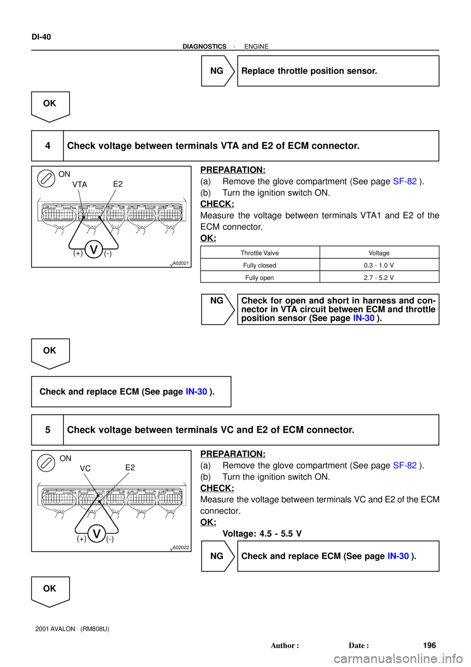
NG Replace throttle position sensor.
OK
4 Check voltage between terminals VTA and E2 of ECM connector.
PREPARATION:
(a) Remove the glove compartment (See page SF-82).
(b) Turn the ignition switch ON.
CHECK:
Measure the voltage between terminals VTA1 and E2 of the
ECM connector.
OK:
Throttle ValveVoltage
Fully closed0.3 - 1.0 V
Fully open2.7 - 5.2 V
NG Check for open and short in harness and con-
nector in VTA circuit between ECM and throttle
position sensor (See page IN-30).
OK
Check and replace ECM (See page IN-30).
5 Check voltage between terminals VC and E2 of ECM connector.
PREPARATION:
(a) Remove the glove compartment (See page SF-82).
(b) Turn the ignition switch ON.
CHECK:
Measure the voltage between terminals VC and E2 of the ECM
connector.
OK:
Voltage: 4.5 - 5.5 V
NG Check and replace ECM (See page IN-30).
OK
Page 925 of 1897
- DIAGNOSTICSENGINE
DI-41
197 Author�: Date�:
2001 AVALON (RM808U)
Check for open in harness and connector in
VC circuit between ECM and throttle position
sensor (See page IN-30).
Page 929 of 1897

1 Are there any other codes (besides DTC P0125) being output?
YES Go to relevant DTC chart (See page DI-14).
NO
2 Connect the OBD I")
- DIAGNOSTICSENGINE
DI-45
201 Author�: Date�:
2001 AVALON (RM808U)
1 Are there any other codes (besides DTC P0125) being output?
YES Go to relevant DTC chart (See page DI-14).
NO
2 Connect the OBD II scan tool or TOYOTA hand-held tester, and read value for
voltage output of A/F sensor (bank 1, 2 sensor 1).
PREPARATION:
(a) Connect the OBD II scan tool or TOYOTA hand-held tester to the DLC3.
(b) Warm up the A/F sensor with the engine speed at 2,500 rpm for approx. 90 sec.
CHECK:
Read the voltage value of the A/F sensor on the screen of OBDII scan tool or TOYOTA hand-held tester
when you perform all the following conditions.
HINT:
The voltage of the AFR+ or AFL+ terminal of the ECM is fixed at 3.3 V and the voltage of the AFR- or AFL-
terminal is fixed at 3.0 V. Therefore, it is impossible to check the A/F sensor output voltage at the terminals
(AFR+, AFL+/AFR-, AFL-) of the ECM.
OK:
ConditionA/F Sensor Voltage Value
Engine idling
Engine racing� Not remains at 3.30 V (0.660 V*)
�Not remains at38V(076V*) or moreDriving at engine speed 1,500 rpm or more and vehicle
speed 40 km/h (25 mph) or more, and operate throttle valve
open and close� Not remains at 3.8 V (0.76 V*) or more
� Not remains at 2.8 V (0.56 V*) or less
*: When you use OBD II scan tool (excluding TOYOTA hand-held tester)
HINT:
�During fuel enrichment, there is a case that the output voltage of the A/F sensor is below 2.8 V (0.56
V*), it is normal.
�During fuel cut, there is a case that the output voltage of the A/F sensor is above 3.8 V (0.76 V*), it
is normal.
�If the output voltage of the A/F sensor remains at 3.30 V (0.660 V*) even after performing all the above
conditions, the A/F sensor circuit may be open.
�If the output voltage of the A/F sensor remains at 3.8 V (0.76 V*) or more, or 2.8 V (0.56 V*) or less
even after performing all the above conditions, the A/F sensor circuit may be short.
*: When you use the OBD II scan tool (excluding TOYOTA hand-held tester).
OK Go to step 9.
NG