Page 780 of 1897
 (c) Stall speed high in R position
�Line pressure too low
�Direct clutch slipping
�1st & reverse brake slipping
�O/D")
- DIAGNOSTICSAUTOMATIC TRANSAXLE
DI-169
325 Author�: Date�:
2001 AVALON (RM808U) (c) Stall speed high in R position
�Line pressure too low
�Direct clutch slipping
�1st & reverse brake slipping
�O/D clutch slipping
(d) Stall speed high in D and R positions
�Line pressure too low
�Improper fluid level
�O/D one-way clutch not operating properly
(b) Measure the time lag.
When the shift lever is shifted while the engine is idling, there will be a certain time lapse or lag before
the shock can be felt. This is used for checking the conditions of the O/D direct clutch, forward clutch,
and 1st & reverse brake.
NOTICE:
�Do the test at normal operating fluid temperature 50 - 80 °C (122 - 176 °F).
�Be sure to allow 1 minute interval between tests.
�Take 3 measurements and take the average value.
(1) Connect an OBD II scan tool or TOYOTA hand-held tester to DLC3.
(2) Fully apply the parking brake.
(3) Start the engine and check idle speed.
Idle speed: 700 ± 50 rpm (In N position and air conditioner OFF)
(4) Shift the shift lever from N to D position. Using a stop watch, measure the time from when the
lever is shifted until the shock is felt.
Time lag: N " D Less than 1.2 seconds
In the same manner, measure the time lag for N " R.
Time lag: N " R Less than 1.5 seconds
Evaluation (If N " D time or N " R time lag is longer than the specified):
ProblemPossible cause
N " D time lag is longer
�Line pressure too low
�Forward clutch worn
�O/D one-way clutch not operating
N " R time lag is longer
�Line pressure too low
�Direct clutch worn
�1st & reverse brake worn
�O/D one-way clutch not operating properly
Page 781 of 1897

7. HYDRAULIC TEST
Measure the line pressure.
NOTICE:
�Do the test at normal operation fluid temperature 50 - 80 °C (")
DI-170
- DIAGNOSTICSAUTOMATIC TRANSAXLE
326 Author�: Date�:
2001 AVALON (RM808U)
7. HYDRAULIC TEST
Measure the line pressure.
NOTICE:
�Do the test at normal operation fluid temperature 50 - 80 °C (122 - 176 °F).
�The line pressure test should always be carried out in pairs. One technician should observe
the conditions of wheels or wheel stoppers outside the vehicle while the other is doing the test.
�Be careful to prevent SST's hose from interfering with the exhaust pipe.
(1) Warm up the ATF.
(2) Remove the test plug on the transaxle case front left side and connect SST (See page AX-33
for the location to connect SST).
SST 09992-00095 (09992-00231, 09992-00271)
(3) Fully apply the parking brake and chock the 4 wheels.
(4) Connect an OBD II scan tool or TOYOTA hand-held tester to DLC3.
(5) Start the engine and check idling speed.
(6) Keep your left foot pressing firmly on the brake pedal and shift into D position.
(7) Measure the line pressure when the engine is idling.
(8) Depress the accelerator pedal all the way down. Quickly read the highest line pressure when
engine speed reaches stall speed.
(9) In the same manner, do the test in R position.
Specified line pressure:
ConditionD position kPa (kgf/cm2, psi)R position kPa (kgf/cm2, psi)
Idling401 - 461 (4.1 - 4.7, 58 - 66)804 - 882 (8.2 - 9.0, 117 - 128)
Stall1,138 - 1,236 (11.6 - 12.6, 165 - 179)1,716 - 1,854 (17.5 - 18.9, 249 - 269)
If the measured pressure is not up to the specified value, recheck the throttle cable adjustment and retest.
Evaluation:
ProblemPossible cause
If the measured values at all positions are higher
�Throttle cable out of adjustment
�Throttle valve defective
�Regulator valve defective
If the measured values at all positions are lower
�Throttle cable out of adjustment
�Throttle valve defective
�Regulator valve defective
�Oil pump defective
�O/D direct clutch defective
If pressure is low in the D position only�D position circuit fluid leakage
�Forward clutch defective
If pressure is low in the R position only
�R position circuit fluid leakage
�Direct clutch defective
�1st & reverse brake defective
Page 783 of 1897

PROBLEM SYMPTOMS TABLE
If a normal code is displayed during the diagnostic trouble code check but the troubl")
DI02I-07
- DIAGNOSTICSAUTOMATIC TRANSAXLE
DI-175
331 Author�: Date�:
2001 AVALON (RM808U)
PROBLEM SYMPTOMS TABLE
If a normal code is displayed during the diagnostic trouble code check but the trouble still occurs, check the
circuits for each symptom in the order given in the charts on the following pages and proceed to the page
given for troubleshooting.
The Matrix Chart is divided into 3 chapters.
Chapter 1: Electronic circuit matrix chart
Chapter 2: On-vehicle repair matrix chart
Chapter 3: Off-vehicle repair matrix chart
If the instruction ºProceed to next circuit inspection shown in matrix chartº is given in the flow chart for each
circuit, proceed to the circuit with the next highest number in the table to continue the check.
If the trouble still occurs even though there are no abnormalities in any of the other circuits, then check and
replace the ECM.
Chapter 1: Electronic circuit matrix chart
SymptomSuspect AreaSee page
No up-shift (A particular gear, from 1st to 3rd gear, is not up-
shifted)ECMIN-30
No up-shift (3rd " O/D)
1. O/D main switch & O/D OFF indicator light circuit
2. O/D cancel signal circuit
3. ECMDI-206
DI-203
IN-30
No down-shift (O/D " 3rd)ECMIN-30
No down-shift (A particular gear, from 3rd to 1st gear, is not
down-shifted)ECMIN-30
No lock-up or No lock-up offECMIN-30
Shift point too high or too lowECMIN-30
Up-shift to 2nd while in L positionECMIN-30
Up-shift to 3rd while in 2 positionECMIN-30
Up-shift to O/D from 3rd while O/D main switch is OFF1. O/D main switch & O/D OFF indicator light circuit
2. ECMDI-206
IN-30
Up-shift to O/D from 3rd while engine is coldECMIN-30
Harsh engagement (N " D)ECMIN-30
Harsh engagement (Any driving position)ECMIN-30
Poor accelerationECMIN-30
Engine stalls when starting off or stoppingECMIN-30
No kick-downECMIN-30
Page 832 of 1897
I13655
W-B88
4F 4E
W-B1
2 D8
Wireless Door
Control Receiver
L-WL-W 9
IK221Body ECU
B4 RDA RDA
E
PRG
+B
P-L1
1
4D
4E
P-L5320
G-R G-R7
B4 PRG
B
BJ6
J/C
II7
1D
FL
MAIN DOME
9
1J
W-L
2
2G 2C1
B
1
1
F7 F6
BBattery J/B No. 4
J/B No. 4
IK2
Driver Side J/B
DCC Engine Room J/B
FL Block W-B
- DIAGNOSTICSBODY CONTROL SYSTEM
DI-651
807 Author�: Date�:
2001 AVALON (RM808U)
Wireless door lock tuner circuit
CIRCUIT DESCRIPTION
The signal from the transmitter will be input to the body ECU through RDA line. RDA line is diagnosed by
the Body ECU, so check DTC also in case of the failure of the wireless function.
WIRING DIAGRAM
DI6LV-01
Page 874 of 1897
AB0119
I00143
I00174
ON
O/D
(-) (+)
DI-582
- DIAGNOSTICSCRUISE CONTROL SYSTEM
738 Author�: Date�:
2001 AVALON (RM808U)
INSPECTION PROCEDURE
1 Check operation of overdrive.
PREPARATION:
Test drive after engine warms up.
CHECK:
Check that overdrive ON e OFF occurs by operation of OD switch ON-OFF.
NG Check and repair electronically controlled
transmission (See page DI-158).
OK
2 Check voltage between terminal OD of harness side connector of cruise control
ECU and body ground.
PREPARATION:
(a) Remove the ECU with connector still connected.
(b) Turn ignition switch ON.
(c) Disconnect the ECU connector.
CHECK:
Measure voltage between terminal OD of harness side connec-
tor of ECU and body ground.
OK:
Voltage: 10 - 14 V
NG Go to step 5.
OK
Page 875 of 1897
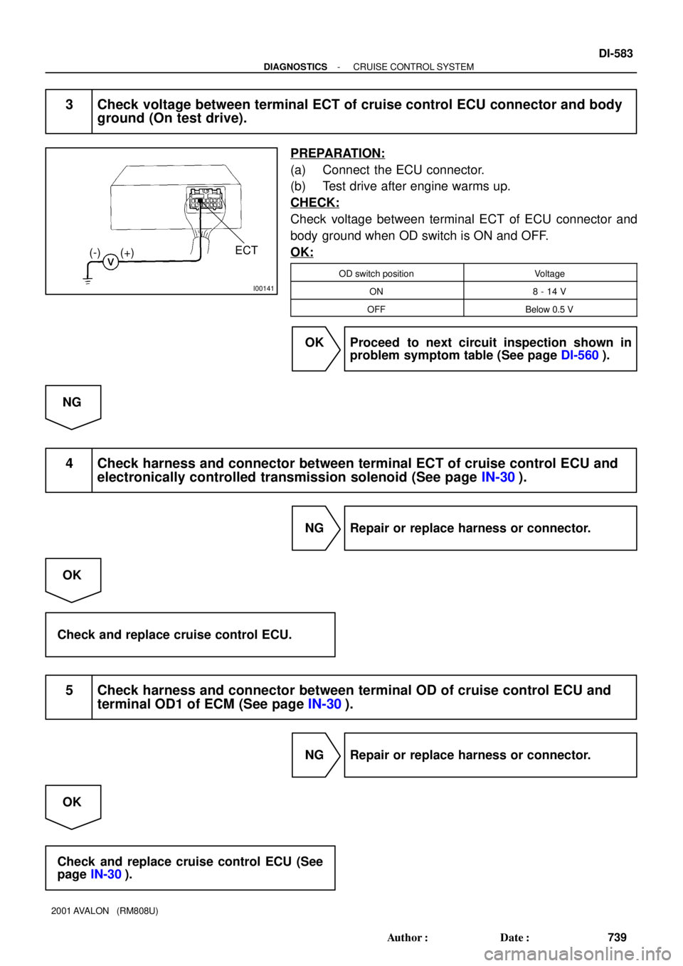
I00141
ECT
(-) (+)
- DIAGNOSTICSCRUISE CONTROL SYSTEM
DI-583
739 Author�: Date�:
2001 AVALON (RM808U)
3 Check voltage between terminal ECT of cruise control ECU connector and body
ground (On test drive).
PREPARATION:
(a) Connect the ECU connector.
(b) Test drive after engine warms up.
CHECK:
Check voltage between terminal ECT of ECU connector and
body ground when OD switch is ON and OFF.
OK:
OD switch positionVoltage
ON8 - 14 V
OFFBelow 0.5 V
OK Proceed to next circuit inspection shown in
problem symptom table (See page DI-560).
NG
4 Check harness and connector between terminal ECT of cruise control ECU and
electronically controlled transmission solenoid (See page IN-30).
NG Repair or replace harness or connector.
OK
Check and replace cruise control ECU.
5 Check harness and connector between terminal OD of cruise control ECU and
terminal OD1 of ECM (See page IN-30).
NG Repair or replace harness or connector.
OK
Check and replace cruise control ECU (See
page IN-30).
Page 877 of 1897
Input SignalIndicator Light
Blinking Pattern
Turn PNP switch
OFF (Shift to posi-
tions except D )LightON
OFFSW ON
SW OFF
- DIAGNOSTICSCRUISE CONTROL SYSTEM
DI-585
741 Author�: Date�:
2001 AVALON (RM808U)
INSPECTION PROCEDURE
1 Check starter operation.
CHECK:
Check that the starter operates normally and that the engine starts.
NG Proceed to engine troubleshooting.
OK
2 Input signal check.
PREPARATION:
See input signal check on page DI-551.
CHECK:
Check the indicator light when shifting into positions except D.
OK:
The indicator light goes off when shifting into posi-
tions except D.
OK Proceed to next circuit inspection shown in
problem symptom table (See page DI-560).
NG
Page 890 of 1897

(a)(b)
No.Operation MethodCRUISE MAIN Indicator Light
Blinking PatternDiagnosis
1 Push SET/COAST switch ON
2Push RES/ACC switch ON
3Push CANCEL switch ON
Turn stop light switch ON
Depress b")
I13679
(a)
(a)(b)
No.Operation MethodCRUISE MAIN Indicator Light
Blinking PatternDiagnosis
1 Push SET/COAST switch ON
2Push RES/ACC switch ON
3Push CANCEL switch ON
Turn stop light switch ON
Depress brake pedal
Turn PNP switch OFF
(Shift to except D position)
4Drive at about 40 km/h
(25 mph)or higher
Drive at about 40 km/h
(25 mph) or below
LightON
OFF
LightON
OFF
LightON
OFFSwitch ON
Switch OFF
LightON
OFFSwitch OFF
Switch ONSET/COAST switch circuit
is normal
RES/ACC switch circuit
is normal
CANCEL switch circuit
is normal
Stop light switch circuit
is normal
PNP switch circuit is
normal
Vehicle Speed Sensor is
normal
LightON
OFF LightON
OFF
1sec.
0.25 sec.0.25 sec.
Turn clutch switch OFF
(Depress clutch pedal)Clutch switch circuit
is normal
- DIAGNOSTICSCRUISE CONTROL SYSTEM
DI-555
711 Author�: Date�:
2001 AVALON (RM808U)
5. INPUT SIGNAL CHECK
HINT:
(1) For check No.1 ~ No.3:
Turn ignition switch ON.
(2) For check No.4:
�Jack up the vehicle.
�Start the engine.
�Shift to D position.
(a) Push the control switch to SET/COAST or RES/ACC posi-
tion and hold it down or up.
(b) Push the main switch ON.
(c) Check that the CRUISE MAIN indicator light blinks twice
or 3 times repeatedly after 3 seconds.
(d) Push the SET/COAST or RES/ACC switch OFF.
(e) Operate each switch as listed in the table below.
(f) Read the blinking pattern of the CRUISE MAIN indicator
light.
(g) After performing the check, turn the main switch OFF.
HINT:
When 2 or more signals are input to the ECU, the lowest num-
bered code will be displayed 1st.