Page 576 of 1897
 SWITCH
CO-29
1222 Author�: Date�:
2001 AVALON (RM808U)
ENGINE COOLANT")
CO037-03
S04602No.1 ECT Switch
P01924
Ohmmeter
B04397
No.2 ECT
Switch
P06722
Ohmmeter
- COOLINGENGINE COOLANT TEMPERATURE (ECT) SWITCH
CO-29
1222 Author�: Date�:
2001 AVALON (RM808U)
ENGINE COOLANT
TEMPERATURE (ECT) SWITCH
INSPECTION
1. DRAIN ENGINE COOLANT
2. INSPECT NO.1 ECT SWITCH
(a) Remove the No.1 ECT switch.
(b) Inspect the No.1 ECT switch.
(1) Using an ohmmeter, check that there is continuity
between the terminals when the coolant tempera-
ture is above 98°C (208°F).
If there is no continuity, replace the switch.
(2) Check that there is no continuity, between the termi-
nals when the coolant temperature is below 88°C
(190°F).
If there is continuity, replace the switch.
(c) Reinstall the No.1 ECT switch.
3. INSPECT NO.2 ECT SWITCH
(a) Remove the No.2 ECT switch.
(b) Inspect the No.2 ECT switch.
(1) Using an ohmmeter, check that there is continuity
between terminals when the coolant temperature is
above 93°C (199°F).
If there is no continuity, replace the switch.
(2) Check that there is no continuity between the termi-
nals when the coolant temperature is below 83°C
(181°F).
If there is continuity, replace the switch.
(c) Reinstall the No.2 ECT switch.
Page 577 of 1897
CO-30
- COOLINGENGINE COOLANT TEMPERATURE (ECT) SWITCH
1223 Author�: Date�:
2001 AVALON (RM808U)
4. REFILL ENGINE COOLANT
5. START ENGINE AND CHECK FOR COOLANT LEAKS
Page 583 of 1897

ON-VEHICLE INSPECTION
1. REMOVE RADIATOR C")
CO09I-02
Z00570
Radiator Cap Tester
30° or More
Radiator Cap
P13014
Radiator Cap
Tester CO-14
- COOLINGRADIATOR
1207 Author�: Date�:
2001 AVALON (RM808U)
ON-VEHICLE INSPECTION
1. REMOVE RADIATOR CAP
CAUTION:
To avoid the danger of being burned, do not remove the ra-
diator cap while the engine and radiator are still hot, as fluid
and steam can be blow out under pressure.
2. INSPECT RADIATOR CAP
NOTICE:
�If the radiator cap has contaminations, always rinse
it with water.
�When performing steps (a) and (b) below, keep the ra-
diator cap tester at an angle of over 30° above the hor-
izontal.
�Before using a radiator cap tester, wet the relief valve
and pressure valve with engine coolant or water.
(a) Using a radiator cap tester, slowly pump the tester and
check that air is coming from the vacuum valve.
Pump speed: 1 push/(3 seconds or more)
NOTICE:
Push the pump at a constant speed.
If air is not coming from the vacuum valve, replace the radiator
cap.
(b) Pump the tester and measure the relief valve opening
pressure.
Pump speed: 1 push within 1 second
NOTICE:
This pump speed is for the first pump only (in order to close
the vacuum valve). After this, the pump speed can be re-
duced.
Standard opening pressure:
83 - 113 kPa (0.85 - 1.15 kgf/cm
2, 12.1 - 16.4 psi)
Minimum opening pressure:
69 kPa (0.7 kgf/cm
2, 10.0 psi)
HINT:
Use the tester's maximum reading as the opening pressure.
If the opening pressure is less than minimum, replace the radia-
tor cap.
3. INSPECT COOLING SYSTEM FOR LEAKS
(a) Fill the radiator with coolant, and attach a radiator cap tes-
ter.
(b) Warm up the engine.
(c) Pump it to 127 kPa (1.3 kgf/cm
2, 18.5 psi), and check that
the pressure does not drop.
If the pressure drops, check the hoses, radiator or water pump
for leaks. If no external leaks are found, check the heater core,
cylinder block and cylinder head.
4. REINSTALL RADIATOR CAP
Page 587 of 1897

REMOVAL
HINT:
At the time of installation, please refer to the following items.
�Start the engine, and check for coo")
CO0WT-01
B09040
- COOLINGRADIATOR
CO-17
1210 Author�: Date�:
2001 AVALON (RM808U)
REMOVAL
HINT:
At the time of installation, please refer to the following items.
�Start the engine, and check for coolant and A/T fluid
leaks.
�Check the A/T fluid level (See page DI-160).
1. REMOVE BATTERY AND BATTERY TRAY
2. REMOVE ENGINE UNDER COVER
3. DRAIN ENGINE COOLANT
4. DISCONNECT NO.3 ENGINE ROOM RELAY BLOCK
FROM RADIATOR
5. DISCONNECT NO.1 COOLING FAN CONNECTOR
6. DISCONNECT WIRE CLAMPS FROM NO.1 FAN
SHROUD
7. DISCONNECT NO.2 COOLING FAN CONNECTOR
8. DISCONNECT NO.1 ECT SWITCH WIRE CONNECTOR
9. DISCONNECT WIRE CLAMPS FROM NO.2 FAN
SHROUD
10. DISCONNECT UPPER RADIATOR HOSE FROM RA-
DIATOR
11. DISCONNECT LOWER RADIATOR HOSE FROM RA-
DIATOR
12. DISCONNECT A/T OIL COOLER HOSES FROM RA-
DIATOR
13. REMOVE RADIATOR AND COOLING FANS AS-
SEMBLY
(a) Remove the 2 bolts and 2 upper supports.
Torque: 12.8 N´m (130 kgf´cm, 9 ft´lbf)
(b) Lift out the radiator, and remove the radiator and cooling
fans assembly.
(c) Remove the 2 lower supports.
14. REMOVE NO.1 ECT SWITCH
15. REMOVE NO.1 COOLING FAN FROM RADIATOR
Remove the 2 bolts and cooling fan.
Torque: 5.0 N´m (50 kgf´cm, 44 in.´lbf)
16. REMOVE NO.2 COOLING FAN FROM RADIATOR
Remove the 2 bolts and cooling fan.
Torque: 5.0 N´m (50 kgf´cm, 44 in.´lbf)
Page 590 of 1897

INSTALLATION
1. PLACE THERMOSTAT IN WATER PUMP
(a) Install a new gasket on to the th")
CO02T-03
B04153Stud BoltJiggle Valve
15°15°
CO-12
- COOLINGTHERMOSTAT
1205 Author�: Date�:
2001 AVALON (RM808U)
INSTALLATION
1. PLACE THERMOSTAT IN WATER PUMP
(a) Install a new gasket on to the thermostat.
(b) Align the thermostat jiggle valve with the upper stud bolt,
and insert the thermostat in the water inlet housing.
HINT:
The jiggle valve may be set within 15° of either side of the pre-
scribed position.
2. INSTALL WATER INLET
Install the water inlet with the 3 nuts.
Torque: 8 N´m (80 kgf´cm, 69 in.´lbf)
3. INSTALL WATER INLET PIPE
(a) Install a new O-ring to the water inlet pipe.
(b) Apply soapy water to the O-ring.
(c) Connect the water inlet pipe to the water inlet.
(d) Install the bolt holding the water inlet pipe to the LH cylin-
der head.
Torque: 19.5 N´m (200 kgf´cm, 14 ft´lbf)
4. INSTALL ENGINE WIRE PROTECTOR
5. CONNECT NO.2 ECT SWITCH CONNECTOR
6. CONNECT HEATER HOSES
7. REINSTALL AIR CLEANER HOSE WITH RESONATOR
8. INSTALL V-BANK COVER
(a) Using 5 mm hexagon wrench, install the V-bank cover
with the 3 cap nuts.
(b) Press down the V-bank cover fastener.
9. FILL WITH ENGINE COOLANT
10. START ENGINE AND CHECK FOR LEAKS
11. RECHECK ENGINE COOLANT LEVEL
Page 596 of 1897
CO02P-03
P12942
CO-8
- COOLINGWATER PUMP
1201 Author�: Date�:
2001 AVALON (RM808U)
INSTALLATION
1. INSTALL WATER PUMP
Install a new gasket and the water pump with the 4 bolts and 2
nuts.
Torque: 8 N´m (80 kgf´cm, 69 in.´lbf)
NOTICE:
Do not get oil on the gasket.
2. INSTALL NO.3 TIMING BELT COVER
(See page EM-59)
3. INSTALL NO.2 IDLER PULLEY (See page EM-21)
4. INSTALL CAMSHAFT TIMING PULLEYS
(See page EM-21)
5. INSTALL TIMING BELT (See page EM-21)
6. FILL WITH ENGINE COOLANT
7. START ENGINE AND CHECK FOR LEAKS
8. RECHECK ENGINE COOLANT LEVEL
Page 601 of 1897
- DIAGNOSTICSANTI-LOCK BRAKE SYSTEM WITH ELECTRONIC
BRAKE FORCE DISTRIBUTION (EBD)DI-239
395 Author�: Date�:
2001 AVALON (RM808U)
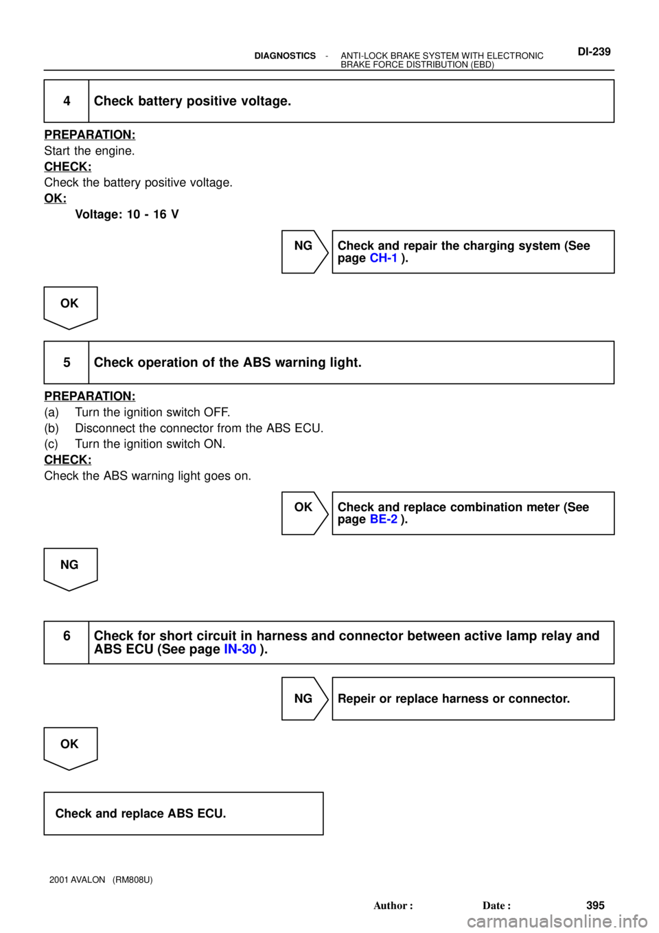
4 Check battery positive voltage.
PREPARATION:
Start the engine.
CHECK:
Check the battery positive voltage.
OK:
Voltage: 10 - 16 V
NG Check and repair the charging system (See
page CH-1).
OK
5 Check operation of the ABS warning light.
PREPARATION:
(a) Turn the ignition switch OFF.
(b) Disconnect the connector from the ABS ECU.
(c) Turn the ignition switch ON.
CHECK:
Check the ABS warning light goes on.
OK Check and replace combination meter (See
page BE-2).
NG
6 Check for short circuit in harness and connector between active lamp relay and
ABS ECU (See page IN-30).
NG Repeir or replace harness or connector.
OK
Check and replace ABS ECU.
Page 606 of 1897
DI6NC-01
F09803
ABS Actuator and ECU
+B
BAT
GND1
GND2 W-B
FL MAINFL Block
ALT
B-L
BatteryA717
A718
A719
A716 L
L
W-B
EE5 5
12 B
10 2F
42F 12H
12G
W-B
ED 1
F8 1
F6
BABS Engine Room R/B No. 5
Engine Room J/B
- DIAGNOSTICSANTI-LOCK BRAKE SYSTEM WITH ELECTRONIC
BRAKE FORCE DISTRIBUTION (EBD)DI-219
375 Author�: Date�:
2001 AVALON (RM808U)
CIRCUIT INSPECTION
DTC 11 ABS Solenoid Relay Circuit
CIRCUIT DESCRIPTION
This relay supplies power to each ABS solenoid. After the ignition switch is turned ON, if the initial check is
OK, the relay goes on.
DTC No.DTC Detecting ConditionTrouble Area
11
When any of the following 1. through 3. is detected:
1. 3 or more solenoids are shown faulty in response and
simultaneously solenoid supply voltage is detected
faulty.
2. Solenoid relay will not be switched OFF.
3. Solenoid relay is frozen in spite of its high valve relay
supply voltage.
�ABS solenoid relay
�ABS solenoid relay circuit
WIRING DIAGRAM