Page 610 of 1897
F09803
ABS Actuator and ECU
+B
BAT
GND1
GND2 W-B
FL MAINFL Block
ALT
B-L
BatteryA717
A718
A719
A716 L
L
W-B
EE5 5
12 B
10 2F
42F 12H
12G
W-B
ED 1
F8 1
F6
BABS Engine Room R/B No. 5
Engine Room J/B
- DIAGNOSTICSANTI-LOCK BRAKE SYSTEM WITH ELECTRONIC
BRAKE FORCE DISTRIBUTION (EBD)DI-223
379 Author�: Date�:
2001 AVALON (RM808U)
DTC 21 - 24 ABS Solenoid Circuit
CIRCUIT DESCRIPTION
This solenoid goes on when signals are received from the ECU, and controls the pressure acting on the
wheel cylinders thus controlling the braking force.
DTC No.DTC Detecting ConditionTrouble Area
21, 22, 23, 24Solenoid signal does not match the check result.�Brake actuator
�Each solenoid circuit
WIRING DIAGRAM
DI6NE-01
Page 634 of 1897
DI-213
369 Author�: Date�:
2001 AVALON (RM808U)
(d)")
BR3890
F02201
DLC1
Ts E
1
Tc
BR3904
0.13 sec. 0.12 sec.
ON
OFF
- DIAGNOSTICSANTI-LOCK BRAKE SYSTEM WITH ELECTRONIC
BRAKE FORCE DISTRIBUTION (EBD)DI-213
369 Author�: Date�:
2001 AVALON (RM808U)
(d) Clear the DTC.
(1) Using SST, connect terminals Tc and E
1 of DLC1.
SST 09843-18020
(2) Turn the ignition switch ON.
(3) Clear the DTC stored in ECU by depressing the
brake pedal 8 times or more within 5 seconds.
(4) Check that the warning light shows the normal
code.
(5) Remove the SST from the terminals of DLC1.
SST 09843-18020
HINT:
Cancellation cannot be done by removing the battery cable or
ECU-IG fuse.
2. SPEED SENSOR SIGNAL CHECK (TEST MODE)
(a) Check the sensor signal.
(1) Using SST, connect terminals Ts and E
1 of DLC1.
SST 09843-18020
(2) Start the engine.
(3) Check that the ABS warning light blinks.
HINT:
If the ABS warning light does not blink, inspect the ABS warning
light circuit (See page DI-243).
(4) Drive vehicle straight forward.
(5) Drive vehicle at a speed faster than 45 km/h (28
mph) for several seconds.
HINT:
If the brake is applied during the check, the check routine must
be started again.
(6) Stop the vehicle.
(7) Using SST, connect terminals Tc and E
1 of DLC1.
SST 09843-18020
(8) Read the number of blinks of the ABS warning light.
HINT:
�See the list of DTC shown on the next page.
�If every sensor is normal, a normal code is output (A cycle
of 0.25 sec. ON and 0.25 sec. OFF is repeated).
�If 2 or more malfunction codes are identified at the same
time, the lowest numbered code will be displayed 1st.
Page 641 of 1897
- DIAGNOSTICSABS WITH EBD & BA & TRAC & VSC SYSTEM
DI-323
479 Author�: Date�:
2001 AVALON (RM808U)
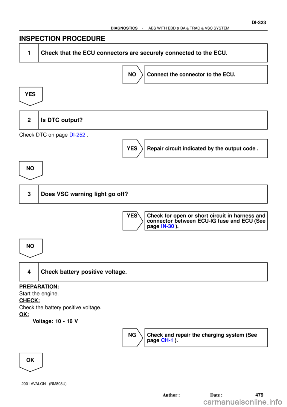
INSPECTION PROCEDURE
1 Check that the ECU connectors are securely connected to the ECU.
NO Connect the connector to the ECU.
YES
2 Is DTC output?
Check DTC on page DI-252.
YES Repair circuit indicated by the output code .
NO
3 Does VSC warning light go off?
YES Check for open or short circuit in harness and
connector between ECU-IG fuse and ECU (See
page IN-30).
NO
4 Check battery positive voltage.
PREPARATION:
Start the engine.
CHECK:
Check the battery positive voltage.
OK:
Voltage: 10 - 16 V
NG Check and repair the charging system (See
page CH-1).
OK
Page 644 of 1897
DI-320
- DIAGNOSTICSABS WITH EBD & BA & TRAC & VSC SYSTEM
476 Author�: Date�:
2001 AVALON (RM808U)
INSPECTION PROCEDURE
1 Check that the ECU connectors are securely connected to the ECU.
NO Connect the connector to the ECU.
YES
2 Is DTC output?
Check DTC on page DI-252.
YES Repair circuit indicated by the output code .
NO
3 Does ABS warning light go off?
YES Check for open or short circuit in harness and
connector between ECU-IG fuse and ECU (See
page IN-30).
NO
4 Check battery positive voltage.
PREPARATION:
Start the engine.
CHECK:
Check the battery positive voltage.
OK:
Voltage: 10 - 16 V
NG Check and repair the charging system (See
page CH-1).
OK
Page 660 of 1897
F07899
Engine Room R/B No. 8
LOCK1
F00044
1
2
3 4
(+) (-) Continuity1 2
3 4
1
2
3 4 Open
Continuity
DI-278
- DIAGNOSTICSABS WITH EBD & BA & TRAC & VSC SYSTEM
434 Author�: Date�:
2001 AVALON (RM808U)
3 Check voltage between terminal 1 of engine room R/B No. 8 (for ABS motor
relay) and body ground.
PREPARATION:
Remove ABS motor relay from engine room R/B No. 8.
CHECK:
Measure the voltage between terminal 1 of engine room R/B
No. 8 (for ABS motor relay) and body ground.
OK:
Voltage: 10 - 14 V
NG Check and repair harness or connector.
OK
4 Check ABS motor relay.
CHECK:
Check continuity between following terminals of motor relay.
OK:
Terminals 3 and 4Continuity
(Reference value 62 W)
Terminals 1 and 2Open
CHECK:
(a) Apply battery positive voltage between terminals 3 and 4.
(b) Check continuity between terminals.
OK:
Terminals 1 and 2Continuity
NG Replace ABS motor relay.
OK
Page 661 of 1897

5 Check continuity between t")
F07900
Engine Room R/B No. 8 ABS Motor Relay
2
ECUBrake Actuator
13 27
- DIAGNOSTICSABS WITH EBD & BA & TRAC & VSC SYSTEM
DI-279
435 Author�: Date�:
2001 AVALON (RM808U)
5 Check continuity between terminal BM (2) of engine room R/B No. 8 (for ABS mo-
tor relay) and terminal MT (27) of ABS & BA & TRAC & VSC ECU.
PREPARATION:
Disconnect the connector from the ABS & BA & TRAC & VSC
ECU.
CHECK:
(a) Check continuity between terminal BM (2) of engine room
R/B No. 8 and terminal GND (28) of ABS & BA & TRAC
& VSC ECU.
(b) Check continuity between terminal BM (2) of engine room
R/B No. 8 and terminal MT (27) of ABS & BA & TRAC &
VSC ECU.
OK:
Continuity
NG Repair or replace harness or brake actuator.
OK
6 Check for open and short circuit in harness and connector between ABS motor
relay and ABS & BA & TRAC &VSC ECU (See page IN-30).
NG Repair or replace harness or connector.
OK
If the same code is still output after the DTC is deleted, check the contact condition of each con-
nection. If the connections are normal, the ECU may be defective.
Page 664 of 1897
F07891
LOCK
1
2
Engine R/B No. 8
DI-282
- DIAGNOSTICSABS WITH EBD & BA & TRAC & VSC SYSTEM
438 Author�: Date�:
2001 AVALON (RM808U)
INSPECTION PROCEDURE
1 Check voltage between terminals 1 and 2 of engine room R/B No. 8 (for ABS so-
lenoid relay).
PREPARATION:
Remove the ABS solenoid relay from engine room R/B No. 8.
CHECK:
Measure the voltage between terminals 1 and 2 of engine room
R/B No. 8 (for ABS solenoid relay).
OK:
Voltage: 10 - 14 V
NG Check and repair harness or connector.
OK
Page 666 of 1897

3")
F07892
ECU ABS
Solenoid
Relay
Brake
Actuator3 Engine Room R/B No. 8
5 25
49 52
6 2650 533 4
54
55
DI-284
- DIAGNOSTICSABS WITH EBD & BA & TRAC & VSC SYSTEM
440 Author�: Date�:
2001 AVALON (RM808U)
3 Check continuity between terminal 3 of engine room R/B No. 8 (for ABS solenoid
relay) and each solenoid terminal of ABS & BA & TRAC & VSC ECU.
PREPARATION:
Disconnect the connector from the ABS & BA & TRAC & VSC
ECU.
CHECK:
Check continuity between terminal 3 of engine room R/B No. 8
and each terminal, 3, 4, 5, 6, 25, 26, 49, 50, 52, 53, 54 and 55
of ECU harness side connector.
OK:
Continuity
HINT:
Resistance of each solenoid coil.
SFLH (5), SRRH (6), SFRH (26), SMC1 (49), SMC2 (50), SRLH
(53): 8 - 9.1 W
SFLR (3), SRRR (4), SRLR (25), SRC2 (52), SRC1 (54), SFRR
(55): 4.0 - 4.6 W
NG Repair or replace harness or brake actuator.
OK
4 Check for open and short circuit in harness and connector between ABS sole-
noid relay and ABS & BA & TRAC & VSC ECU (See page IN-30).
NG Repair or replace harness or connector.
OK
If the same code is still output after the DTC is deleted, check the contact condition of each con-
nection. If the connections are normal, the ECU may be defective.