Page 895 of 1897
A02040
ON
E1+B
(-) (+)
A02344
ON
IGSW
(-) (+)
- DIAGNOSTICSENGINE
DI-149
305 Author�: Date�:
2001 AVALON (RM808U)
INSPECTION PROCEDURE
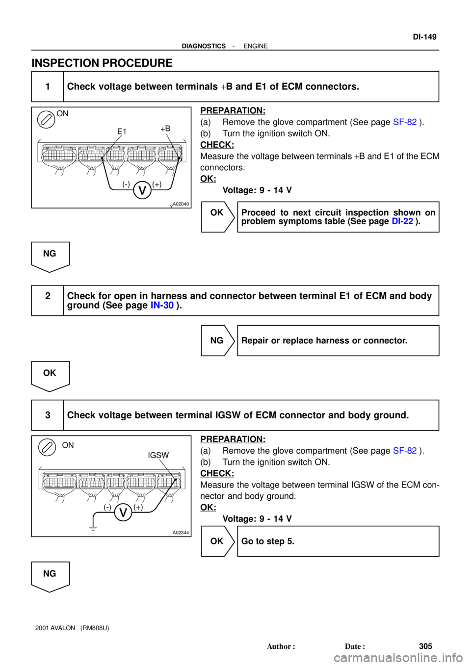
1 Check voltage between terminals +B and E1 of ECM connectors.
PREPARATION:
(a) Remove the glove compartment (See page SF-82).
(b) Turn the ignition switch ON.
CHECK:
Measure the voltage between terminals +B and E1 of the ECM
connectors.
OK:
Voltage: 9 - 14 V
OK Proceed to next circuit inspection shown on
problem symptoms table (See page DI-22).
NG
2 Check for open in harness and connector between terminal E1 of ECM and body
ground (See page IN-30).
NG Repair or replace harness or connector.
OK
3 Check voltage between terminal IGSW of ECM connector and body ground.
PREPARATION:
(a) Remove the glove compartment (See page SF-82).
(b) Turn the ignition switch ON.
CHECK:
Measure the voltage between terminal IGSW of the ECM con-
nector and body ground.
OK:
Voltage: 9 - 14 V
OK Go to step 5.
NG
Page 896 of 1897
A02345
ON
MREL
(-) (+)
DI-150
- DIAGNOSTICSENGINE
306 Author�: Date�:
2001 AVALON (RM808U)
4 Check AM2 fuse (See page DI-1 17, step 10).
NG Check for short in all harness and components
connected to AM2 fuse.
OK
5 Check ignition switch (See page BE-16).
NG Replace ignition switch.
OK
Check and repair harness and connector be-
tween battery and ignition switch, and igni-
tion switch and ECM.
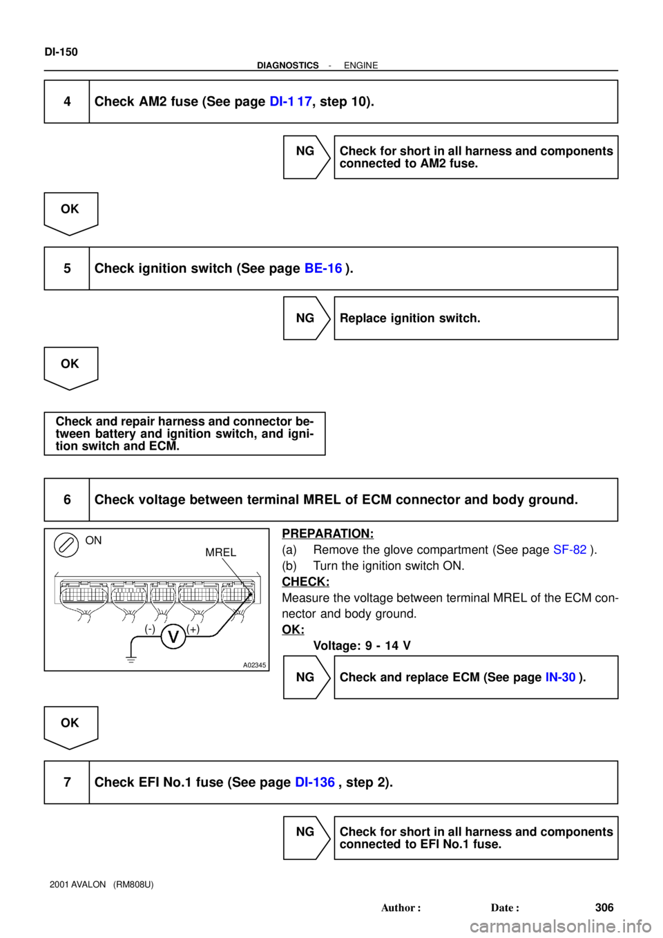
6 Check voltage between terminal MREL of ECM connector and body ground.
PREPARATION:
(a) Remove the glove compartment (See page SF-82).
(b) Turn the ignition switch ON.
CHECK:
Measure the voltage between terminal MREL of the ECM con-
nector and body ground.
OK:
Voltage: 9 - 14 V
NG Check and replace ECM (See page IN-30).
OK
7 Check EFI No.1 fuse (See page DI-136, step 2).
NG Check for short in all harness and components
connected to EFI No.1 fuse.
Page 897 of 1897
A11423
Engine Room J/B
EFI No.2
Fuse
- DIAGNOSTICSENGINE
DI-151
307 Author�: Date�:
2001 AVALON (RM808U)
OK
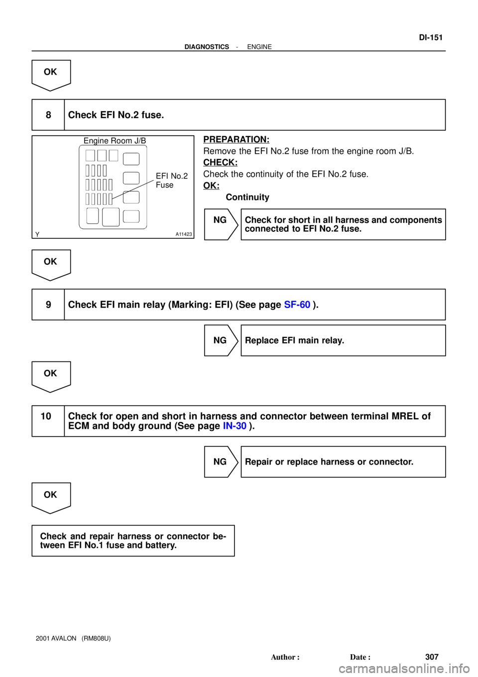
8 Check EFI No.2 fuse.
PREPARATION:
Remove the EFI No.2 fuse from the engine room J/B.
CHECK:
Check the continuity of the EFI No.2 fuse.
OK:
Continuity
NG Check for short in all harness and components
connected to EFI No.2 fuse.
OK
9 Check EFI main relay (Marking: EFI) (See page SF-60).
NG Replace EFI main relay.
OK
10 Check for open and short in harness and connector between terminal MREL of
ECM and body ground (See page IN-30).
NG Repair or replace harness or connector.
OK
Check and repair harness or connector be-
tween EFI No.1 fuse and battery.
Page 899 of 1897
A11672
From
Terminal
MREL of
ECM From
Battery1 5
2 B-R3
C/OPN Relay Driver Side R/B No.6
6
66 6 B-R 1
IF1 W-R
W-B
2C
2F13
EFI
No.1 AM2
EFI Relay 5
1B
EDEngine Room J/B
43
22B
1 2G
46 7
2C 2
BK 7 4
IF1ECM
E01
ID2E8
Fuel
Pump
AL-B
W-BJ11
J/CFC
G-B3
5 41
L-B B-O IG SwitchW-B
W-R
L-O
BE6653A02330
A02405
ON
- DIAGNOSTICSENGINE
DI-153
309 Author�: Date�:
2001 AVALON (RM808U)
WIRING DIAGRAM
INSPECTION PROCEDURE
TOYOTA hand-held tester:
1 Connect TOYOTA hand-held tester, and check operation of fuel pump.
PREPARATION:1
(a) Connect the TOYOTA hand-held tester to the DLC3.
(b) Turn the ignition switch ON and push the TOYOTA hand-
held tester main switch ON.
(c) Use the ACTIVE TEST mode to operate the fuel pump.
CHECK:
Check that the pulsation damper screw rises up when the fuel
pump is operated by the TOYOTA hand-held tester.
OK:
The pulsation damper screw rises up.
OK Check for starter signal circuit
(See page DI-142).
NG
Page 900 of 1897
A02064
ON
FC
(+) (-)
DI-154
- DIAGNOSTICSENGINE
310 Author�: Date�:
2001 AVALON (RM808U)
2 Check for ECM power source circuit (See page DI-148).
NG Repair or replace.
OK
3 Check circuit opening relay (Marking: C/OPN) (See page SF-63).
NG Replace circuit opening relay.
OK
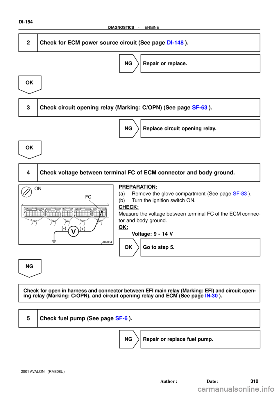
4 Check voltage between terminal FC of ECM connector and body ground.
PREPARATION:
(a) Remove the glove compartment (See page SF-83).
(b) Turn the ignition switch ON.
CHECK:
Measure the voltage between terminal FC of the ECM connec-
tor and body ground.
OK:
Voltage: 9 - 14 V
OK Go to step 5.
NG
Check for open in harness and connector between EFI main relay (Marking: EFI) and circuit open-
ing relay (Marking: C/OPN), and circuit opening relay and ECM (See page IN-30).
5 Check fuel pump (See page SF-6).
NG Repair or replace fuel pump.
Page 901 of 1897
A02042
ON
FC
- DIAGNOSTICSENGINE
DI-155
311 Author�: Date�:
2001 AVALON (RM808U)
OK
6 Check for open in harness and connector between circuit opening relay (Mark-
ing: C/OPN) and fuel pump, and fuel pump and body ground
(See page IN-30).
NG Repair or replace harness or connector.
OK
Check and replace ECM (See page IN-30).
OBD II scan tool (excluding TOYOTA hand-held tester):
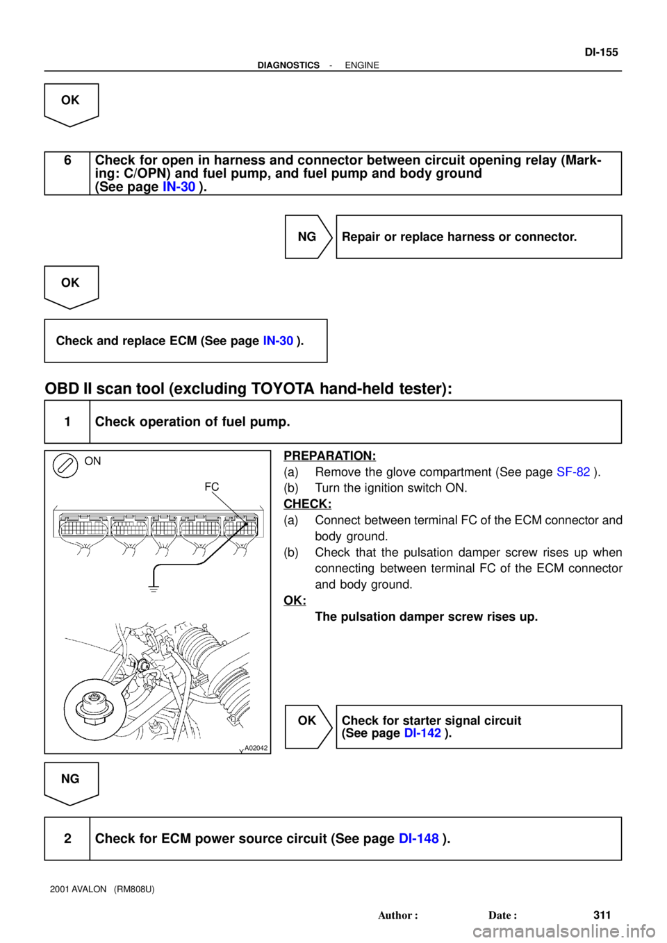
1 Check operation of fuel pump.
PREPARATION:
(a) Remove the glove compartment (See page SF-82).
(b) Turn the ignition switch ON.
CHECK:
(a) Connect between terminal FC of the ECM connector and
body ground.
(b) Check that the pulsation damper screw rises up when
connecting between terminal FC of the ECM connector
and body ground.
OK:
The pulsation damper screw rises up.
OK Check for starter signal circuit
(See page DI-142).
NG
2 Check for ECM power source circuit (See page DI-148).
Page 902 of 1897
A02064
ON
FC
(+) (-)
DI-156
- DIAGNOSTICSENGINE
312 Author�: Date�:
2001 AVALON (RM808U)
NG Repair or replace.
OK
3 Check circuit opening relay (Marking: C/OPN) (See page SF-63).
NG Replace circuit opening relay.
OK
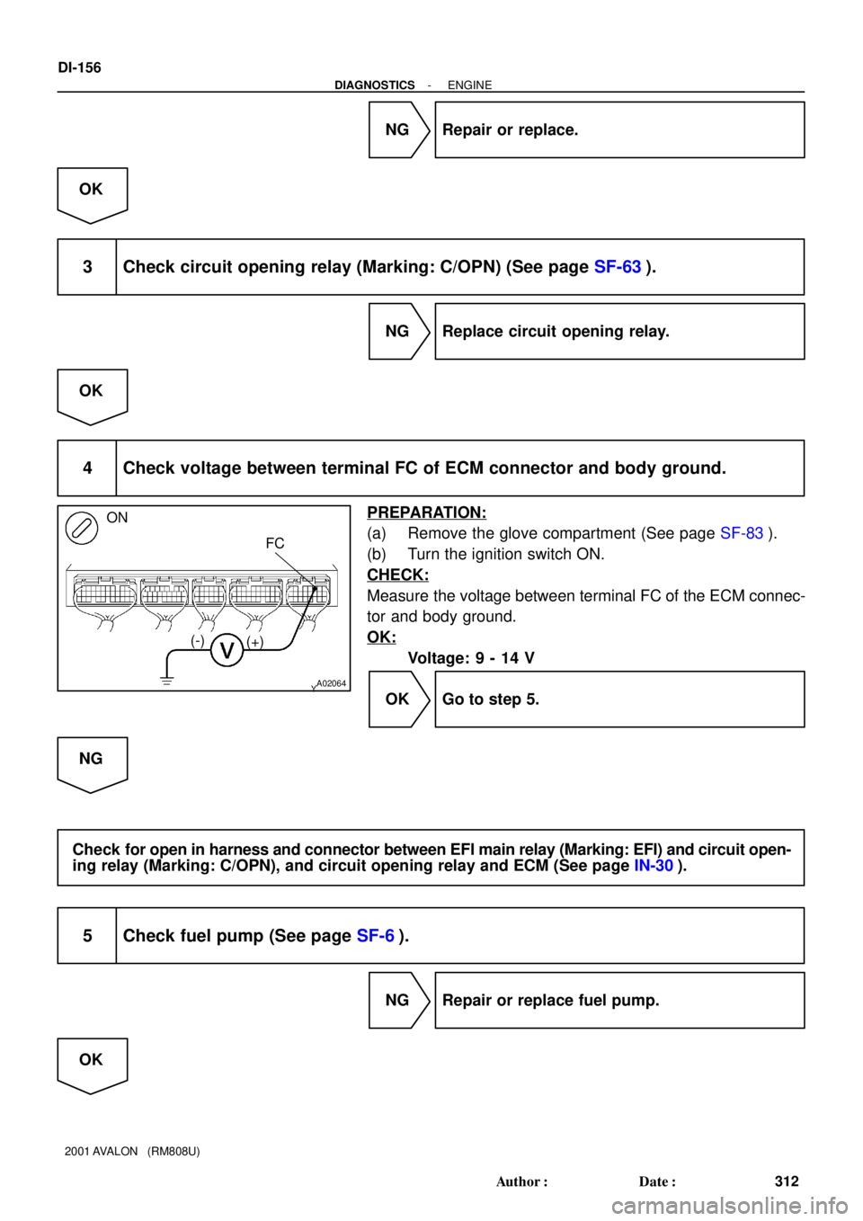
4 Check voltage between terminal FC of ECM connector and body ground.
PREPARATION:
(a) Remove the glove compartment (See page SF-83).
(b) Turn the ignition switch ON.
CHECK:
Measure the voltage between terminal FC of the ECM connec-
tor and body ground.
OK:
Voltage: 9 - 14 V
OK Go to step 5.
NG
Check for open in harness and connector between EFI main relay (Marking: EFI) and circuit open-
ing relay (Marking: C/OPN), and circuit opening relay and ECM (See page IN-30).
5 Check fuel pump (See page SF-6).
NG Repair or replace fuel pump.
OK
Page 903 of 1897
- DIAGNOSTICSENGINE
DI-157
313 Author�: Date�:
2001 AVALON (RM808U)
6 Check for open in harness and connector between circuit opening relay (Mark-
ing: C/OPN) and fuel pump, and fuel pump and body ground
(See page IN-30).
NG Repair or replace harness or connector.
OK
Check and replace ECM (See page IN-30).