Page 193 of 3051
SAT261K
SPORT Indicator Lamp Does Not Come On=NLAT0295SYMPTOM:
SPORT indicator lamp does not come on for about 2 seconds
when turning ignition switch to ªONº.
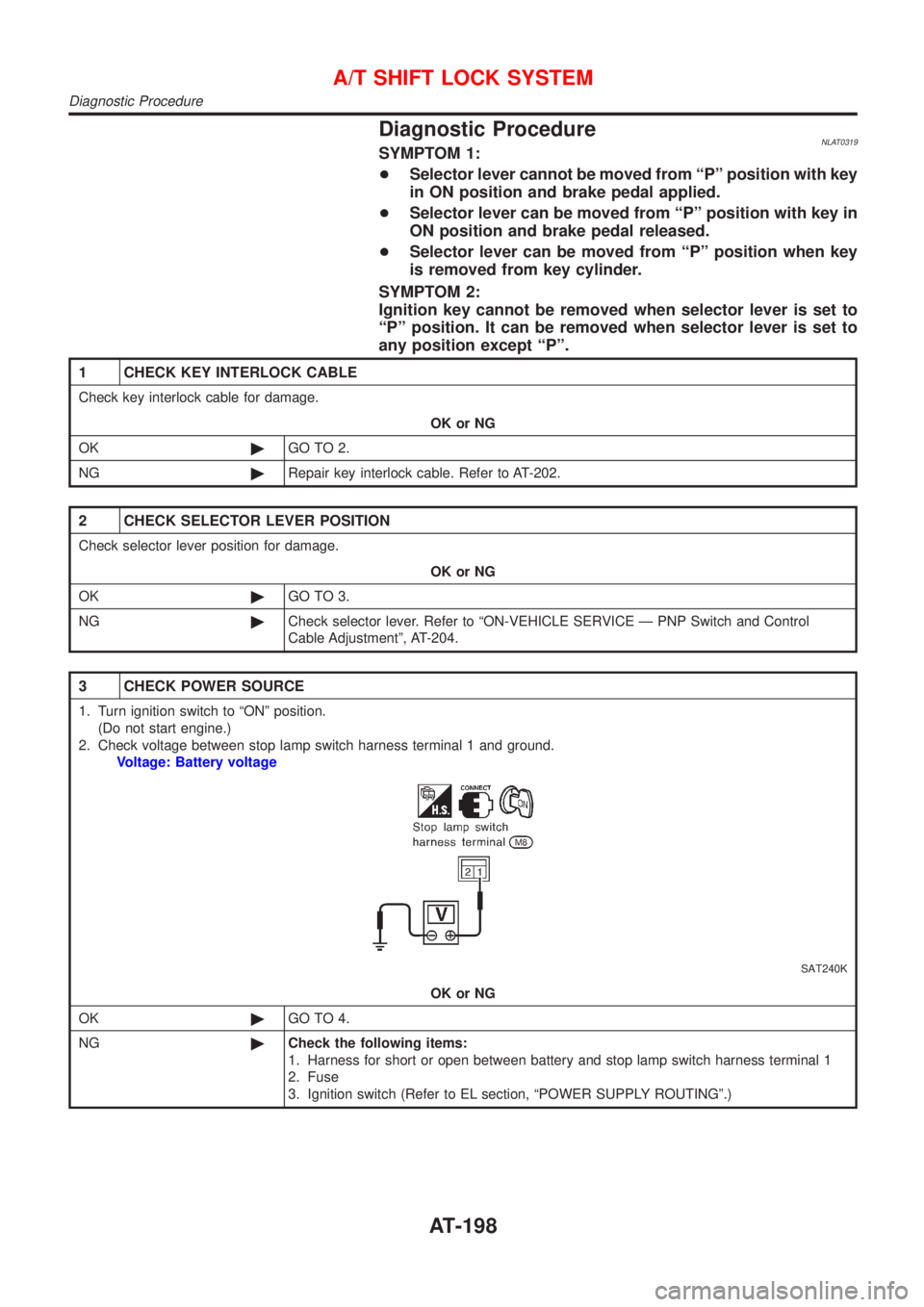
1 CHECK TCM POWER SOURCE
SAT262K
1. Turn ignition switch to ªOFFº position.
2. Check voltage between TCM terminal 28 and ground.
Voltage: Battery voltage
OK or NG
OK©GO TO 2.
NG©Check the following items:
+Harness for short or open between battery terminal and TCM terminal 28 (Main har-
ness).
+Refer to ªWiring Diagram Ð AT Ð MAINº, AT-62.
+Ignition switch and fuse Refer to EL section, ªPOWER SUPPLY ROUTINGº.
TROUBLE DIAGNOSES FOR SYMPTOMS
SPORT Indicator Lamp Does Not Come On
AT-192
Page 199 of 3051

Diagnostic ProcedureNLAT0319SYMPTOM 1:
+Selector lever cannot be moved from ªPº position with key
in ON position and brake pedal applied.
+Selector lever can be moved from ªPº position with key in
ON position and brake pedal released.
+Selector lever can be moved from ªPº position when key
is removed from key cylinder.
SYMPTOM 2:
Ignition key cannot be removed when selector lever is set to
ªPº position. It can be removed when selector lever is set to
any position except ªPº.
1 CHECK KEY INTERLOCK CABLE
Check key interlock cable for damage.
OK or NG
OK©GO TO 2.
NG©Repair key interlock cable. Refer to AT-202.
2 CHECK SELECTOR LEVER POSITION
Check selector lever position for damage.
OK or NG
OK©GO TO 3.
NG©Check selector lever. Refer to ªON-VEHICLE SERVICE Ð PNP Switch and Control
Cable Adjustmentº, AT-204.
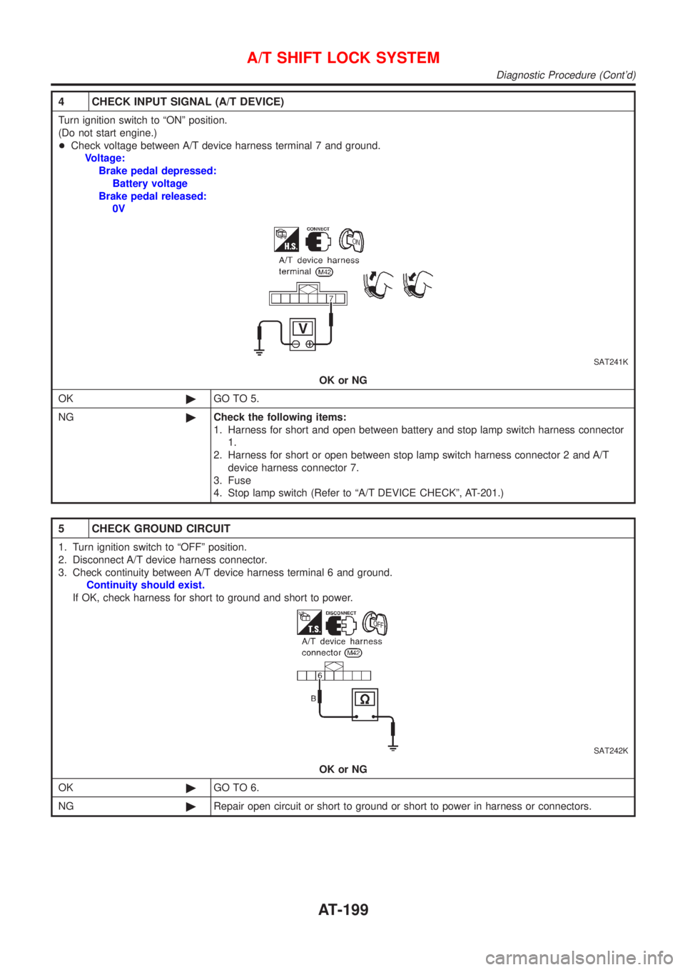
3 CHECK POWER SOURCE
1. Turn ignition switch to ªONº position.
(Do not start engine.)
2. Check voltage between stop lamp switch harness terminal 1 and ground.
Voltage: Battery voltage
SAT240K
OK or NG
OK©GO TO 4.
NG©Check the following items:
1. Harness for short or open between battery and stop lamp switch harness terminal 1
2. Fuse
3. Ignition switch (Refer to EL section, ªPOWER SUPPLY ROUTINGº.)
A/T SHIFT LOCK SYSTEM
Diagnostic Procedure
AT-198
Page 200 of 3051

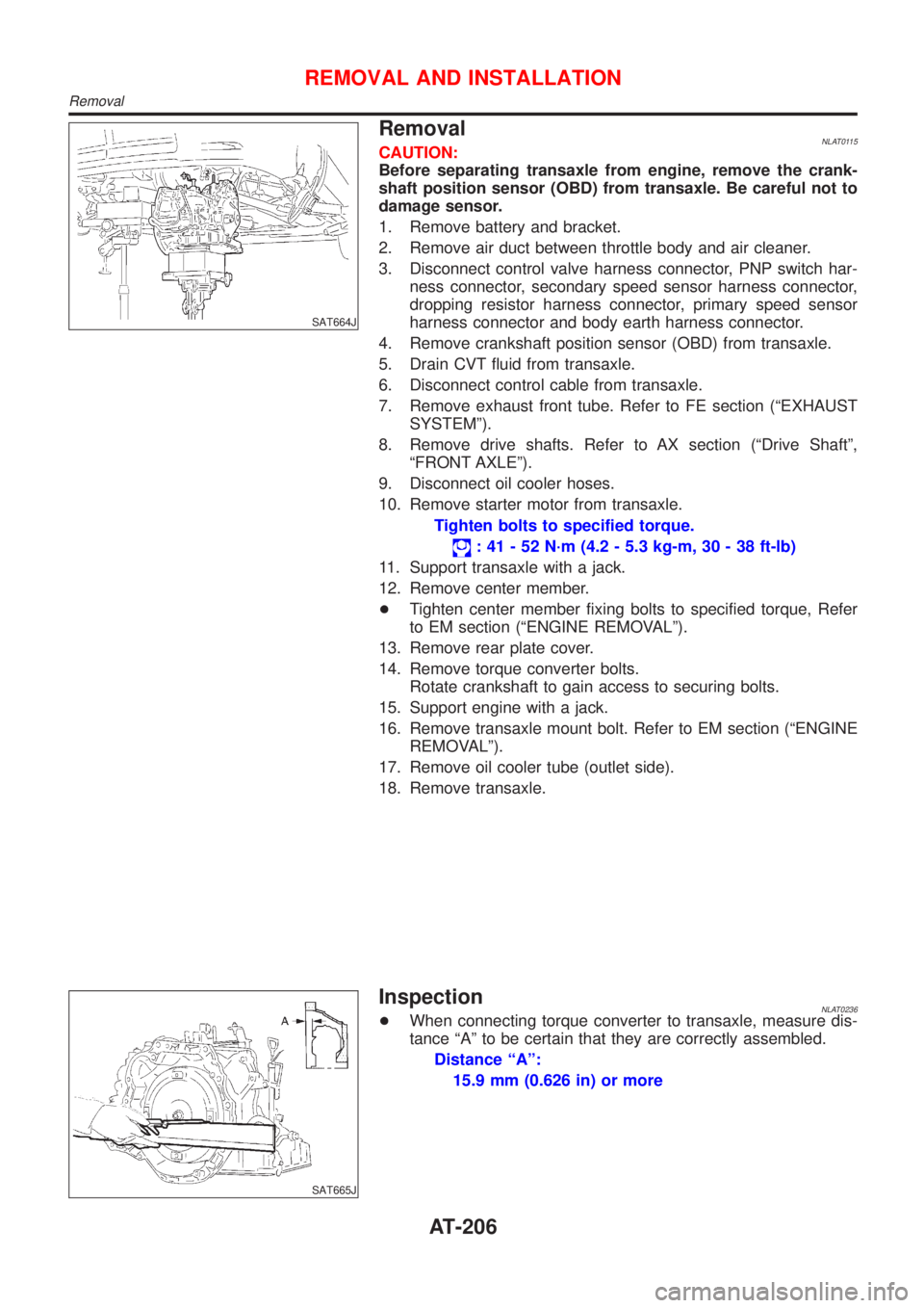
4 CHECK INPUT SIGNAL (A/T DEVICE)
Turn ignition switch to ªONº position.
(Do not start engine.)
+Check voltage between A/T device harness terminal 7 and ground.
Voltage:
Brake pedal depressed:
Battery voltage
Brake pedal released:
0V
SAT241K
OK or NG
OK©GO TO 5.
NG©Check the following items:
1. Harness for short and open between battery and stop lamp switch harness connector
1.
2. Harness for short or open between stop lamp switch harness connector 2 and A/T
device harness connector 7.
3. Fuse
4. Stop lamp switch (Refer to ªA/T DEVICE CHECKº, AT-201.)
5 CHECK GROUND CIRCUIT
1. Turn ignition switch to ªOFFº position.
2. Disconnect A/T device harness connector.
3. Check continuity between A/T device harness terminal 6 and ground.
Continuity should exist.
If OK, check harness for short to ground and short to power.
SAT242K
OK or NG
OK©GO TO 6.
NG©Repair open circuit or short to ground or short to power in harness or connectors.
A/T SHIFT LOCK SYSTEM
Diagnostic Procedure (Cont'd)
AT-199
Page 207 of 3051

SAT664J
RemovalNLAT0115CAUTION:
Before separating transaxle from engine, remove the crank-
shaft position sensor (OBD) from transaxle. Be careful not to
damage sensor.
1. Remove battery and bracket.
2. Remove air duct between throttle body and air cleaner.
3. Disconnect control valve harness connector, PNP switch har-
ness connector, secondary speed sensor harness connector,
dropping resistor harness connector, primary speed sensor
harness connector and body earth harness connector.
4. Remove crankshaft position sensor (OBD) from transaxle.
5. Drain CVT fluid from transaxle.
6. Disconnect control cable from transaxle.
7. Remove exhaust front tube. Refer to FE section (ªEXHAUST
SYSTEMº).
8. Remove drive shafts. Refer to AX section (ªDrive Shaftº,
ªFRONT AXLEº).
9. Disconnect oil cooler hoses.
10. Remove starter motor from transaxle.
Tighten bolts to specified torque.
: 41 - 52 N´m (4.2 - 5.3 kg-m, 30 - 38 ft-lb)
11. Support transaxle with a jack.
12. Remove center member.
+Tighten center member fixing bolts to specified torque, Refer
to EM section (ªENGINE REMOVALº).
13. Remove rear plate cover.
14. Remove torque converter bolts.
Rotate crankshaft to gain access to securing bolts.
15. Support engine with a jack.
16. Remove transaxle mount bolt. Refer to EM section (ªENGINE
REMOVALº).
17. Remove oil cooler tube (outlet side).
18. Remove transaxle.
SAT665J
InspectionNLAT0236+When connecting torque converter to transaxle, measure dis-
tance ªAº to be certain that they are correctly assembled.
Distance ªAº:
15.9 mm (0.626 in) or more
REMOVAL AND INSTALLATION
Removal
AT-206
Page 245 of 3051

pressure such that vehicle stopping time equals 3 to 5 sec-
onds.
3. To cool the brake system, drive the vehicle at 50 km/h (31
MPH) for 1 minute without stopping.
4. Repeat steps 1 to 3, 10 times or more to complete the burnish-
ing procedure.
NBR357
Bleeding Brake SystemNLBR0009CAUTION:
+Carefully monitor brake fluid level at master cylinder dur-
ing bleeding operation.
+Fill reservoir with new brake fluid“DOT 4”. Make sure it is
full at all times while bleeding air out of system.
+Place a container under master cylinder to avoid spillage
of brake fluid.
+For models with ABS, turn ignition switch OFF and dis-
connect ABS actuator connectors or battery ground cable.
SBR419C
+Bleed air in the following order.
Right rear brake→Left front brake→Left rear brake→Right
front brake
1. Connect a transparent vinyl tube to air bleeder valve.
2. Fully depress brake pedal several times.
3. With brake pedal depressed, open air bleeder valve to release
air.
4. Close air bleeder valve.
5. Release brake pedal slowly.
6. Repeat steps 2. through 5. until clear brake fluid comes out of
air bleeder valve.
ON-VEHICLE SERVICE
Brake Burnishing Procedure (Cont’d)
BR-8
Page 295 of 3051

CONSULT-IINLBR0092CONSULT-II APPLICATION TO ABSNLBR0092S01
ITEMSELF-DIAGNOSTIC
RESULTSDATA MONITOR ACTIVE TEST
Front right wheel sensor X X—
Front left wheel sensor X X—
Rear right wheel sensor X X—
Rear left wheel sensor X X—
Stop lamp switch—X—
Front right inlet solenoid valve X X X
Front right outlet solenoid valve X X X
Front left inlet solenoid valve X X X
Front left outlet solenoid valve X X X
Rear right inlet solenoid valve X X X
Rear right outlet solenoid valve X X X
Rear left inlet solenoid valve X X X
Rear left outlet solenoid valve X X X
Actuator solenoid valve relay X X—
Actuator motor relay
(ABS MOTOR is shown on the ACTIVE TEST
screen.)XXX
ABS warning lamp—X—
Battery voltage X X—
Control unit X——
X: Applicable
—: Not applicable
ECU (ABS CONTROL UNIT) PART NUMBER MODENLBR0092S02Ignore the ECU part number displayed in the ECU PART NUMBER MODE. Refer to parts catalog to order
the ABS actuator and electric unit.
NBR371
CONSULT-II Inspection ProcedureNLBR0093SELF-DIAGNOSIS PROCEDURENLBR0093S011. Turn ignition switch OFF.
2. Connect CONSULT-II to data link connector.
3. Start engine.
4. Drive vehicle over 30 km/h (19 MPH) for at least one minute.
ON BOARD DIAGNOSTIC SYSTEM DESCRIPTIONABS
CONSULT-II
BR-58
Page 298 of 3051
![NISSAN ALMERA TINO 2001 Service Repair Manual Diagnostic item Diagnostic item is detected when ...Reference
Page
RR RH OUT ABS SOL
[SHORT]+Circuit for rear right outlet solenoid valve is shorted.
(An abnormally high output voltage is entered.)BR- NISSAN ALMERA TINO 2001 Service Repair Manual Diagnostic item Diagnostic item is detected when ...Reference
Page
RR RH OUT ABS SOL
[SHORT]+Circuit for rear right outlet solenoid valve is shorted.
(An abnormally high output voltage is entered.)BR-](/manual-img/5/57352/w960_57352-297.png)
Diagnostic item Diagnostic item is detected when ...Reference
Page
RR RH OUT ABS SOL
[SHORT]+Circuit for rear right outlet solenoid valve is shorted.
(An abnormally high output voltage is entered.)BR-74
RR LH OUT ABS SOL
[SHORT]+Circuit for rear left outlet solenoid valve is shorted.
(An abnormally high output voltage is entered.)BR-74
ABS ACTUATOR RELAY
[ABNORMAL]+Actuator solenoid valve relay is ON, even control unit sends off signal.
+Actuator solenoid valve relay is OFF, even control unit sends on signal.BR-74
ABS MOTOR RELAY
[ABNORMAL]+Circuit for actuator motor is open or shorted.
+Actuator motor relay is stuck.BR-77
BATTERY VOLT
[ABNORMAL]+Power source voltage supplied to ABS control unit is abnormally low. BR-79
CONTROL UNIT+Function of calculation in ABS control unit has failed. BR-81
*1: Be sure to confirm the ABS warning lamp illuminates when the ignition switch is turned ON after repairing the shorted sensor circuit,
but the lamp goes out when driving the vehicle over 30 km/h (19 MPH) for one minute in accordance with SELF-DIAGNOSIS
PROCEDURE.
PBR455D
DATA MONITOR PROCEDURENLBR0093S031. Turn ignition switch OFF.
2. Connect CONSULT-II to data link connector.
3. Turn ignition switch ON.
4. Touch“START”on CONSULT-II screen.
C2SSE01
5. Touch“ABS”.
C2SDM01
6. Touch“DATA MONITOR”.
7. Touch“SETTING”on“SELECT MONITOR ITEM”screen.
8. Touch“LONG TIME”on“SET RECORDING COND”screen.
9. Touch“START”on“SELECT MONITOR ITEM”.
ON BOARD DIAGNOSTIC SYSTEM DESCRIPTIONABS
CONSULT-II Inspection Procedure (Cont’d)
BR-61
Page 300 of 3051

DATA MONITOR MODENLBR0093S05
MONITOR ITEM CONDITION SPECIFICATION
FR RH SENSOR
FR LH SENSOR
RR RH SENSOR
RR LH SENSORDrive vehicle.
(Each wheel is rotating.)Displays computed vehicle speed from wheel sensor signal.
Almost the same speed as speedometer.
STOP LAMP SWTurn ignition switch ON and
depress brake pedal.Depress the pedal: ON
Release the pedal: OFF
FR RH IN SOL
FR RH OUT SOL
FR LH IN SOL
FR LH OUT SOL
RR IN SOL
RR OUT SOL
RL IN SOL
RL OUT SOLIgnition switch is turned ON or
engine is running.Operating conditions for each solenoid valve are indicated.
ABS is not operating: OFF
ACTUATOR RELAY
Ignition switch is turned ON or
engine is running.Displays ON/OFF condition of ABS actuator relay.
When turning ignition switch ON, ABS actuator relay is oper-
ated.
MOTOR RELAYABS is not operating: OFF
ABS is operating: ON
WARNING LAMPWarning lamp is turned on: ON
Warning lamp is turned off: OFF
BATTERY VOLT Power supply voltage for control unit
ACTIVE TEST MODENLBR0093S06
TEST ITEM CONDITION JUDGEMENT
FR RH SOLENOID
FR LH SOLENOID
RR RH SOLENOID
RR LH SOLENOID
Ignition switch is turned ON.Brake fluid pressure control operation
IN SOL OUT SOL
UP (Increase): OFF OFF
KEEP (Hold): ON OFF
DOWN (Decrease): ON ON
ABS MOTORABS actuator motor
ON: Motor runs
OFF: Motor stops
NOTE:
Active test will automatically stop ten seconds after the test starts. (TEST IS STOPPED monitor shows ON.)
ON BOARD DIAGNOSTIC SYSTEM DESCRIPTIONABS
CONSULT-II Inspection Procedure (Cont’d)
BR-63