Page 2974 of 3051

System DescriptionNLSC0004M/T MODELSNLSC0004S01Power is supplied at all times
+through 40A fusible link (letterB, located in the fuse and fusible link box)
+to ignition switch terminal 1.
With the ignition switch in START position, power is supplied
+from ignition switch terminal 5
+to starter motor harness connector terminal 1.
The starter motor plunger closes and provides a closed circuit between the battery and starter motor. The
starter motor is grounded to the engine block. With power and ground supplied, cranking occurs and the engine
starts.
A/T MODELSNLSC0004S02Power is supplied at all times
+through 40A fusible link (letterB, located in the fuse and fusible link box)
+to ignition switch terminal 1.
With the ignition switch in the START position, power is supplied
+from ignition switch terminal 5
+to park/neutral position relay terminal 5.
With the ignition switch ON or START position, power is supplied
+through 10A fuse [No. 20, located in the fuse block (J/B)]
+to park/neutral position (PNP) relay terminal 1.
With the selector lever in the P or N position, ground is supplied
+to park/neutral position relay terminal 2 through the park/neutral position switch
+from body grounds, F9 and F10.
Then park/neutral position relay is energized and power is supplied
+from park/neutral position relay terminal 3
+to starter motor harness connector terminal 1.
The starter motor plunger closes and provides a closed circuit between the battery and starter motor. The
starter motor is grounded to the engine block. With power and ground supplied, cranking occurs and the engine
starts.
STARTING SYSTEM
System Description
SC-13
Page 2977 of 3051
Trouble DiagnosesNLSC0018If any abnormality is found, immediately disconnect battery negative terminal.
SEL761W
STARTING SYSTEM
Trouble Diagnoses
SC-16
Page 2981 of 3051

NEL644
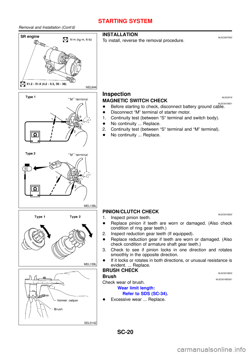
INSTALLATIONNLSC0007S02To install, reverse the removal procedure.
MEL138L
InspectionNLSC0019MAGNETIC SWITCH CHECKNLSC0019S01+Before starting to check, disconnect battery ground cable.
+Disconnect“M”terminal of starter motor.
1. Continuity test (between“S”terminal and switch body).
+No continuity ... Replace.
2. Continuity test (between“S”terminal and“M”terminal).
+No continuity ... Replace.
MEL139L
PINION/CLUTCH CHECKNLSC0019S021. Inspect pinion teeth.
+Replace pinion if teeth are worn or damaged. (Also check
condition of ring gear teeth.)
2. Inspect reduction gear teeth (If equipped).
+Replace reduction gear if teeth are worn or damaged. (Also
check condition of armature shaft gear teeth.)
3. Check to see if pinion locks in one direction and rotates
smoothly in the opposite direction.
+If it locks or rotates in both directions, or unusual resistance is
evident. ... Replace.
SEL014Z
BRUSH CHECKNLSC0019S03BrushNLSC0019S0301Check wear of brush.
Wear limit length:
Refer to SDS (SC-34).
+Excessive wear ... Replace.
STARTING SYSTEM
Removal and Installation (Cont’d)
SC-20
Page 2985 of 3051

System DescriptionNLSC0009The alternator provides DC voltage to operate the vehicle’s electrical system and to keep the battery charged.
The voltage output is controlled by the IC regulator.
Power is supplied at all times to alternator terminal 4 (S) through:
+10A fuse (No. 33, located in the fuse and fusible link box).
Terminal B supplies power to charge the battery and operate the vehicle’s electrical system. Output voltage
is controlled by the IC regulator at terminal 4 (S) detecting the input voltage. The charging circuit is protected
by the 80A (QG engine models except for Northen Europe and cold spec.) or 100A (SR, YD engine models
and QG engine models for Northen Europe and cold spec.) fusible link.
The alternator is grounded to the engine block.
With the ignition switch in the ON or START position, power is supplied
+through 10A fuse [No. 30, located in the fuse block (J/B)]
+to combination meter terminal 9
Ground is supplied to terminal 22 of the combination meter through terminal 3 (L) of the alternator. With power
and ground supplied, the charge warning lamp will illuminate. When the alternator is providing sufficient volt-
age with the engine running, the ground is opened and the charge warning lamp will go off.
If the charge warning lamp illuminates with the engine running, a fault is indicated.
CHARGING SYSTEM
System Description
SC-24
Page 2988 of 3051
Trouble DiagnosesNLSC0011Before conducting an alternator test, make sure that the battery is fully charged. A 30-volt voltmeter and suit-
able test probes are necessary for the test. The alternator can be checked easily by referring to the Inspec-
tion Table.
+Before starting, inspect the fusible link.
+Use fully charged battery.
WITH IC REGULATORNLSC0011S01
SEL338V
NOTE:
+If the inspection result is OK even though the charging system is malfunctioning, check the B terminal
connection. (Check the tightening torque.)
+When field circuit is open, check condition of rotor coil, rotor slip ring and brush. If necessary, replace faulty
parts with new ones.
MALFUNCTION INDICATORNLSC0011S02The IC regulator warning function activates to illuminate“CHARGE”warning lamp, if any of the following
symptoms occur while alternator is operating:
+Excessive voltage is produced.
+No voltage is produced.
CHARGING SYSTEM
Trouble Diagnoses
SC-27
Page 2995 of 3051

BatteryNLSC0014
Applied model QG engine YD22 engine
TypeYUASA type code YUASA type code
025 027 065 075 079 067 096
Capacity V-AH 12 - 52 12-55 12-50 12-42 12-60 12-64
StarterNLSC0015
Type0 001 116 006 D7E31 S114-800B S1114-871 M8T75371
BOSCH make VALEO make HITACHI make MITSUBISHI make
Non-reduction Non-reduction Reduction Reduction Reduction
Applied model QG engine SR engine YD22 engine
System voltage V12
No-loadTerminal voltage V 11.5 11.0 11.0 11.0 11.0
Current A Less than 48 45 Less than 90 Less than 90 Less than 145
Revolution rpm More than 5,800 12,000 More than 2,700 More than 2,300 More than 3,400
Minimum diameter of commutator mm
(in)33.5 (1.319) 28.2 (1,110) 28.0 (1.102) 31.4 (1.236)
Minimum length of brush mm (in) 3.5 (0.138) 6.15 (0.242) 10.5 (0.413) 11.0 (0.433)
Brush spring tension N (kg, lb)5.2 (0.53, 1.17) at
7.5 mm (0.295 in)
brush length16.2 - 19.8
(1.65 - 2.02,
3.46 - 4.45)12.7 - 17.7
(1.3 - 1.8,
2.9 - 4.0)26.5 - 36.3
(2.7 - 3.7,
6.0 - 8.2)
Clearance between bearing metal and
armature shaft mm (in)—0.05 (0.002) Less than 0.2 (0.008)—
Clearance“!”between pinion front edge
and pinion stopper mm (in)0.0 - 3.9
(0 - 0.154)Max. 1 (0.039) 0.3 - 2.5 (0.012 - 0.098)—
Movement“!”in height of pinion assem-
bly mm (in)—Max. 12.2 (0.480)—0.5 - 2.0
(0.020 - 0.079)
AlternatorNLSC0016
TypeLR180-762 LR190-747 LR1100-724 A2TB3891
HITACHI make MITSUBISHI make
Applied model QG engine SR engine YD engine SR engine
Nominal rating V-A 12-80 12-90 12-100 12-90
Ground polarityNegative
Minimum revolutions under no-load (When
13.5V is applied) rpmLess than 1,000 Less than 1,300
Hot output current (When 13.5V is applied)
A/rpmMore than 23/1,300
More than 65/2,500
More than 87/5,000More than 34/1,300
More than 83/2,500
More than 91/5,000More than 22/1,300
More than 64/2,500
More than 85/5,000
Regulated output voltage V 14.1 - 14.7
Minimum length of brush mm (in) 6.0 (0.236) 5.0 (0.197)
Brush spring pressure N (g, oz) 1.0 - 3.43 (102 - 350, 3.60 - 12.34)4.8 - 5.0
(490 - 610, 17.28 -
21.51)
Slip ring minimum diameter mm (in) 6.0 (1.024) 22.1 (0.870)
Rotor coil resistance at 20°C (68°F)Ω2.67 2.31 1.8 - 2.1
SERVICE DATA AND SPECIFICATIONS (SDS)
Battery
SC-34