Page 99 of 3051
SAT684JA
Component InspectionNLAT0057TORQUE CONVERTER CLUTCH SOLENOID VALVENLAT0057S01+For removal, refer to AT-206.
Resistance CheckNLAT0057S0101+Check resistance between two terminals.
Solenoid valve Terminal No.Resistance
(Approx.)
Torque converter
clutch solenoid
valve9Ground of TCC
solenoid valve10-20W
SAT685JA
Operation CheckNLAT0057S0102+Check solenoid valve by listening for its operating sound while
applying battery voltage to the terminal and ground of TCC
solenoid valve.
DTC P0740 TORQUE CONVERTER CLUTCH
SOLENOID VALVE
EURO-OBD
Component Inspection
AT-98
Page 104 of 3051
SAT686JA
Component Inspection=NLAT0063LINE PRESSURE SOLENOID VALVENLAT0063S01+For removal, refer to AT-206.
Resistance CheckNLAT0063S0101+Check resistance between two terminals.
Solenoid valve Terminal No.Resistance
(Approx.)
Line pressure
solenoid valve8Ground of line
pressure solenoid
valve2.5-5W
SAT687JA
Operation CheckNLAT0063S0102+Check solenoid valve by listening for its operating sound while
applying battery voltage to the terminal and ground of line
pressure solenoid valve.
SAT232K
DROPPING RESISTORNLAT0063S02+Check resistance between two terminals.
Resistance:
11.2 - 12.8W
DTC P0745 LINE PRESSURE SOLENOID VALVEEURO-OBD
Component Inspection
AT-103
Page 105 of 3051

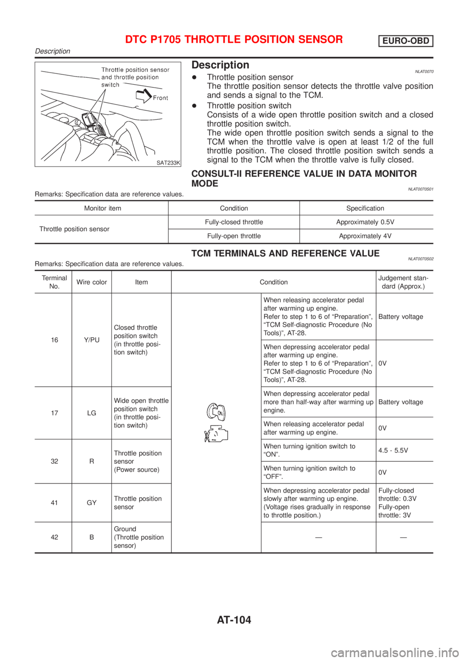
SAT233K
DescriptionNLAT0070+Throttle position sensor
The throttle position sensor detects the throttle valve position
and sends a signal to the TCM.
+Throttle position switch
Consists of a wide open throttle position switch and a closed
throttle position switch.
The wide open throttle position switch sends a signal to the
TCM when the throttle valve is open at least 1/2 of the full
throttle position. The closed throttle position switch sends a
signal to the TCM when the throttle valve is fully closed.
CONSULT-II REFERENCE VALUE IN DATA MONITOR
MODE
NLAT0070S01Remarks: Specification data are reference values.
Monitor item Condition Specification
Throttle position sensorFully-closed throttle Approximately 0.5V
Fully-open throttle Approximately 4V
TCM TERMINALS AND REFERENCE VALUENLAT0070S02Remarks: Specification data are reference values.
Terminal
No.Wire color Item ConditionJudgement stan-
dard (Approx.)
16 Y/PUClosed throttle
position switch
(in throttle posi-
tion switch)
When releasing accelerator pedal
after warming up engine.
Refer to step 1 to 6 of ªPreparationº,
ªTCM Self-diagnostic Procedure (No
Tools)º, AT-28.Battery voltage
When depressing accelerator pedal
after warming up engine.
Refer to step 1 to 6 of ªPreparationº,
ªTCM Self-diagnostic Procedure (No
Tools)º, AT-28.0V
17 LGWide open throttle
position switch
(in throttle posi-
tion switch)When depressing accelerator pedal
more than half-way after warming up
engine.Battery voltage
When releasing accelerator pedal
after warming up engine.0V
32 RThrottle position
sensor
(Power source)When turning ignition switch to
ªONº.4.5 - 5.5V
When turning ignition switch to
ªOFFº.0V
41 GYThrottle position
sensorWhen depressing accelerator pedal
slowly after warming up engine.
(Voltage rises gradually in response
to throttle position.)Fully-closed
throttle: 0.3V
Fully-open
throttle: 3V
42 BGround
(Throttle position
sensor)ÐÐ
DTC P1705 THROTTLE POSITION SENSOREURO-OBD
Description
AT-104
Page 138 of 3051

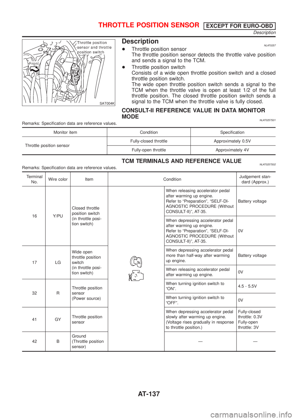
SAT004K
DescriptionNLAT0257+Throttle position sensor
The throttle position sensor detects the throttle valve position
and sends a signal to the TCM.
+Throttle position switch
Consists of a wide open throttle position switch and a closed
throttle position switch.
The wide open throttle position switch sends a signal to the
TCM when the throttle valve is open at least 1/2 of the full
throttle position. The closed throttle position switch sends a
signal to the TCM when the throttle valve is fully closed.
CONSULT-II REFERENCE VALUE IN DATA MONITOR
MODE
NLAT0257S01Remarks: Specification data are reference values.
Monitor item Condition Specification
Throttle position sensorFully-closed throttle Approximately 0.5V
Fully-open throttle Approximately 4V
TCM TERMINALS AND REFERENCE VALUENLAT0257S02Remarks: Specification data are reference values.
Terminal
No.Wire color Item ConditionJudgement stan-
dard (Approx.)
16 Y/PUClosed throttle
position switch
(in throttle posi-
tion switch)
When releasing accelerator pedal
after warming up engine.
Refer to ªPreparationº, ªSELF-DI-
AGNOSTIC PROCEDURE (Without
CONSULT-II)º, AT-35.Battery voltage
When depressing accelerator pedal
after warming up engine.
Refer to ªPreparationº, ªSELF-DI-
AGNOSTIC PROCEDURE (Without
CONSULT-II)º, AT-35.0V
17 LGWide open
throttle position
switch
(in throttle posi-
tion switch)When depressing accelerator pedal
more than half-way after warming
up engine.Battery voltage
When releasing accelerator pedal
after warming up engine.0V
32 RThrottle position
sensor
(Power source)When turning ignition switch to
ªONº.4.5 - 5.5V
When turning ignition switch to
ªOFFº.0V
41 GYThrottle position
sensorWhen depressing accelerator pedal
slowly after warming up engine.
(Voltage rises gradually in response
to throttle position.)Fully-closed
throttle: 0.3V
Fully-open
throttle: 3V
42 BGround
(Throttle position
sensor)ÐÐ
THROTTLE POSITION SENSOREXCEPT FOR EURO-OBD
Description
AT-137
Page 164 of 3051
SAT686JA
Component Inspection=NLAT0276LINE PRESSURE SOLENOID VALVENLAT0276S01+For removal, refer to AT-206.
Resistance CheckNLAT0276S0101+Check resistance between two terminals.
Solenoid valve Terminal No.Resistance
(Approx.)
Line pressure
solenoid valve8 Ground 2.5 - 5W
SAT687JA
Operation CheckNLAT0276S0102+Check solenoid valve by listening for its operating sound while
applying battery voltage to the terminal and ground.
SAT232K
DROPPING RESISTORNLAT0276S02+Check resistance between two terminals.
Resistance:
11.2 - 12.8W
LINE PRESSURE
SOLENOID VALVE
EXCEPT FOR EURO-OBD
Component Inspection
AT-163
Page 170 of 3051
SAT684JA
Component InspectionNLAT0280TORQUE CONVERTER CLUTCH SOLENOID VALVENLAT0280S01+For removal, refer to AT-206.
Resistance CheckNLAT0280S0101+Check resistance between two terminals.
Solenoid valve Terminal No.Resistance
(Approx.)
Torque converter
clutch solenoid
valve9 Ground 10 - 20W
SAT685JA
Operation CheckNLAT0280S0102+Check solenoid valve by listening for its operating sound while
applying battery voltage to the terminal and ground.
TORQUE CONVERTER CLUTCH
SOLENOID VALVE
EXCEPT FOR EURO-OBD
Component Inspection
AT-169
Page 186 of 3051

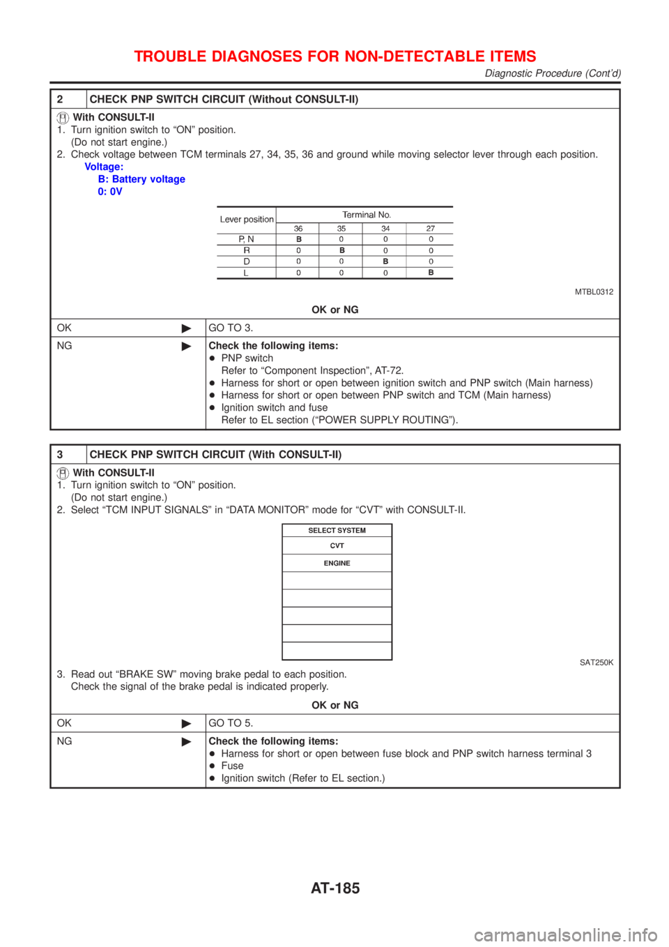
2 CHECK PNP SWITCH CIRCUIT (Without CONSULT-II)
With CONSULT-II
1. Turn ignition switch to ªONº position.
(Do not start engine.)
2. Check voltage between TCM terminals 27, 34, 35, 36 and ground while moving selector lever through each position.
Voltage:
B: Battery voltage
0: 0V
MTBL0312
OK or NG
OK©GO TO 3.
NG©Check the following items:
+PNP switch
Refer to ªComponent Inspectionº, AT-72.
+Harness for short or open between ignition switch and PNP switch (Main harness)
+Harness for short or open between PNP switch and TCM (Main harness)
+Ignition switch and fuse
Refer to EL section (ªPOWER SUPPLY ROUTINGº).
3 CHECK PNP SWITCH CIRCUIT (With CONSULT-II)
With CONSULT-II
1. Turn ignition switch to ªONº position.
(Do not start engine.)
2. Select ªTCM INPUT SIGNALSº in ªDATA MONITORº mode for ªCVTº with CONSULT-II.
SAT250K
3. Read out ªBRAKE SWº moving brake pedal to each position.
Check the signal of the brake pedal is indicated properly.
OK or NG
OK©GO TO 5.
NG©Check the following items:
+Harness for short or open between fuse block and PNP switch harness terminal 3
+Fuse
+Ignition switch (Refer to EL section.)
TROUBLE DIAGNOSES FOR NON-DETECTABLE ITEMS
Diagnostic Procedure (Cont'd)
AT-185
Page 187 of 3051

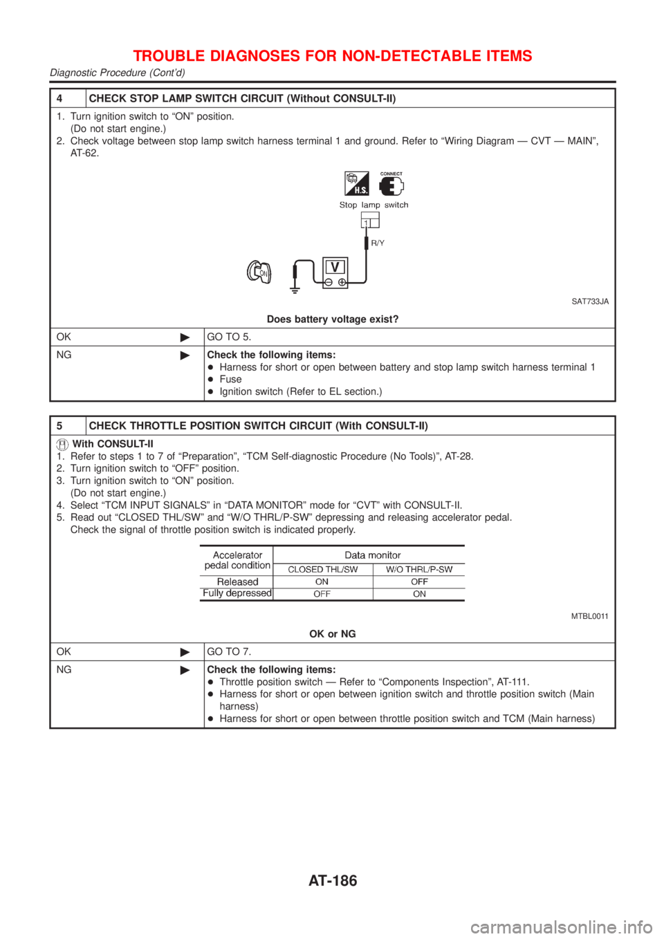
4 CHECK STOP LAMP SWITCH CIRCUIT (Without CONSULT-II)
1. Turn ignition switch to ªONº position.
(Do not start engine.)
2. Check voltage between stop lamp switch harness terminal 1 and ground. Refer to ªWiring Diagram Ð CVT Ð MAINº,
AT-62.
SAT733JA
Does battery voltage exist?
OK©GO TO 5.
NG©Check the following items:
+Harness for short or open between battery and stop lamp switch harness terminal 1
+Fuse
+Ignition switch (Refer to EL section.)
5 CHECK THROTTLE POSITION SWITCH CIRCUIT (With CONSULT-II)
With CONSULT-II
1. Refer to steps 1 to 7 of ªPreparationº, ªTCM Self-diagnostic Procedure (No Tools)º, AT-28.
2. Turn ignition switch to ªOFFº position.
3. Turn ignition switch to ªONº position.
(Do not start engine.)
4. Select ªTCM INPUT SIGNALSº in ªDATA MONITORº mode for ªCVTº with CONSULT-II.
5. Read out ªCLOSED THL/SWº and ªW/O THRL/P-SWº depressing and releasing accelerator pedal.
Check the signal of throttle position switch is indicated properly.
MTBL0011
OK or NG
OK©GO TO 7.
NG©Check the following items:
+Throttle position switch Ð Refer to ªComponents Inspectionº, AT-111.
+Harness for short or open between ignition switch and throttle position switch (Main
harness)
+Harness for short or open between throttle position switch and TCM (Main harness)
TROUBLE DIAGNOSES FOR NON-DETECTABLE ITEMS
Diagnostic Procedure (Cont'd)
AT-186