2001 NISSAN ALMERA TINO battery
[x] Cancel search: batteryPage 353 of 3051
Removal and InstallationNLBT0012CAUTION:
+Disconnect ground terminal from battery in advance.
+Disconnect air bag system line in advance.
+Never tamper with or force air bag lid open, as this may adversely affect air bag performance.
+Be careful not to scratch pad and other parts.
INSTRUMENT PANEL ASSEMBLY
Removal and Installation
BT-22
Page 377 of 3051
Removal and InstallationNLBT0018+When removing or installing the seat trim, carefully handle it to keep dirt out and avoid damage.
CAUTION:
+Before removing the front seat, turn the ignition switch off, disconnect both battery cables and wait
at least 3 minutes (models with side airbag).
+Do not drop, tilt, or bump the side air bag module installed in the seat. Always handle it with care.
+Disconnect the side air bag harness connector and heated seat harness connector from under the
seat before removing the seat.
+Disconnect the side air bag harness connector before removing the seat back. Refer to RS-27,
ªFront Side Air Bag Moduleº for details.
FRONT SEAT
Removal and Installation
BT-46
Page 439 of 3051
On Board Diagnosis Logic.....................................1219
DTC Confirmation Procedure ................................1219
Wiring Diagram ......................................................1221
Diagnostic Procedure ............................................1223
DTC P1251 P4.SPILL/V CIRC..................................1225
Description .............................................................1225
CONSULT-II Reference Value in Data Monitor
Mode ......................................................................1225
ECM Terminals and Reference Value ...................1226
On Board Diagnosis Logic.....................................1226
DTC Confirmation Procedure ................................1226
Wiring Diagram ......................................................1228
Diagnostic Procedure ............................................1230
DTC P1337 P2.DTC PULSE SIG..............................1232
Description .............................................................1232
CONSULT-II Reference Value in Data Monitor
Mode ......................................................................1232
ECM Terminals and Reference Value ...................1233
On Board Diagnosis Logic.....................................1233
DTC Confirmation Procedure ................................1233
Wiring Diagram ......................................................1235
Diagnostic Procedure ............................................1237
DTC P1341 P1.CAM POS SEN................................1239
Description .............................................................1239
CONSULT-II Reference Value in Data Monitor
Mode ......................................................................1239
ECM Terminals and Reference Value ...................1240
On Board Diagnosis Logic.....................................1240
DTC Confirmation Procedure ................................1240
Wiring Diagram ......................................................1242
Diagnostic Procedure ............................................1244
DTC P1600 P3.PUMP COMM LINE..........................1246
Description .............................................................1246
CONSULT-II Reference Value in Data Monitor
Mode ......................................................................1246
ECM Terminals and Reference Value ...................1247
On Board Diagnosis Logic.....................................1247
DTC Confirmation Procedure ................................1247
Wiring Diagram ......................................................1249
Diagnostic Procedure ............................................1251
DTC P1603 ECM 12, DTC P1607 ECM 2.................1253
Description .............................................................1253
On Board Diagnosis Logic.....................................1253
DTC Confirmation Procedure ................................1253
Diagnostic Procedure ............................................1254
DTC P1620 ECM RLY...............................................1255
ECM Terminals and Reference Value ...................1255
On Board Diagnosis Logic.....................................1255
DTC Confirmation Procedure ................................1255
Wiring Diagram ......................................................1256
Diagnostic Procedure ............................................1258DTC P1621 ECM 15..................................................1260
Description .............................................................1260
On Board Diagnosis Logic.....................................1260
DTC Confirmation Procedure ................................1260
Diagnostic Procedure ............................................1261
DTC P1660 BATTERY VOLTAGE............................1262
On Board Diagnosis Logic.....................................1262
DTC Confirmation Procedure ................................1262
Diagnostic Procedure ............................................1262
DTC P1690 P5.PUMP C/MODULE...........................1264
Description .............................................................1264
CONSULT-II Reference Value in Data Monitor
Mode ......................................................................1264
ECM Terminals and Reference Value ...................1265
On Board Diagnosis Logic.....................................1265
DTC Confirmation Procedure ................................1265
Diagnostic Procedure ............................................1266
GLOW CONTROL SYSTEM.....................................1267
Description .............................................................1267
ECM Terminals and Reference Value ...................1268
Wiring Diagram ......................................................1269
Diagnostic Procedure ............................................1271
EGR VOLUME CONTROL SYSTEM........................1277
Description .............................................................1277
CONSULT-II Reference Value in Data Monitor
Mode ......................................................................1278
ECM Terminals and Reference Value ...................1278
Wiring Diagram ......................................................1279
Diagnostic Procedure ............................................1281
SWIRL CONTROL VALVE CONTROL SOLENOID
VALVE........................................................................1285
Description .............................................................1285
CONSULT-II Reference Value in Data Monitor
Mode ......................................................................1286
ECM Terminals and Reference Value ...................1286
Wiring Diagram ......................................................1287
Diagnostic Procedure ............................................1289
START SIGNAL.........................................................1293
Wiring Diagram ......................................................1293
Diagnostic Procedure ............................................1295
PARK/NEUTRAL POSITION (PNP) SWITCH
(WHERE FITTED)......................................................1297
Description .............................................................1297
CONSULT-II Reference Value in Data Monitor
Mode ......................................................................1297
ECM Terminals and Reference Value ...................1297
Wiring Diagram ......................................................1298
Diagnostic Procedure ............................................1299
AIR CONDITIONER CONTROL................................1301
Wiring Diagram ......................................................1301
MI & DATA LINK CONNECTORS............................1303
Wiring Diagram ......................................................1303
CONTENTS(Cont'd)
EC-14
Page 446 of 3051
Precautions for Supplemental Restraint System
(SRS) ªAIR BAGº and ªSEAT BELT
PRE-TENSIONERº
NLEC1262The Supplemental Restraint System ªAIR BAGº and ªSEAT BELT PRE-TENSIONERº, used along with a seat
belt, help to reduce the risk or severity of injury to the driver and front passenger in a frontal collision. The
Supplemental Restraint System consists of air bag modules (located in the center of the steering wheel and
on the instrument panel on the passenger side), seat belt pre-tensioners, a diagnosis sensor unit, warning
lamp, wiring harness and spiral cable.
In addition to the supplemental air bag modules for a frontal collision, the supplemental side air bag used along
with the seat belt helps to reduce the risk or severity of injury to the driver and front passenger in a side col-
lision. The supplemental side air bag consists of air bag modules (located in the outer side of front seats),
satellite sensor, diagnosis sensor unit (one of components of supplemental air bags for a frontal collision),
wiring harness, warning lamp (one of components of supplemental air bags for a frontal collision). Information
necessary to service the system safely is included in theRS sectionof this Service Manual.
WARNING:
+To avoid rendering the SRS inoperative, which could increase the risk of personal injury or death
in the event of a collision which would result in air bag inflation, all maintenance must be performed
by an authorized NISSAN dealer.
+Improper maintenance, including incorrect removal and installation of the SRS, can lead to per-
sonal injury caused by unintentional activation of the system.
+Do not use electrical test equipment on any circuit related to the SRS unless instructed to in this
Service Manual. SRS wiring harnesses can be identified with yellow harness connector (and with
yellow harness protector or yellow insulation tape before the harness connectors).
Precautions for On Board Diagnostic (OBD)
System of Engine
NLEC0003The ECM has an on board diagnostic system. It will light up the malfunction indicator (MI) to warn the driver
of a malfunction causing emission deterioration.
CAUTION:
+Be sure to turn the ignition switch ªOFFº and disconnect the negative battery terminal before any
repair or inspection work. The open/short circuit of related switches, sensors, solenoid valves, etc.
will cause the MI to light up.
+Be sure to connect and lock the connectors securely after work. A loose (unlocked) connector will
cause the MI to light up due to the open circuit. (Be sure the connector is free from water, grease,
dirt, bent terminals, etc.)
+Certain systems and components, especially those related to OBD, may use a new style slide-
locking type harness connector.
For description and how to disconnect, refer to EL section, ªDescriptionº, ªHARNESS CONNEC-
TORº.
+Be sure to route and secure the harnesses properly after work. The interference of the harness with
a bracket, etc. may cause the MI to light up due to the short circuit.
+Be sure to connect rubber tubes properly after work. A misconnected or disconnected rubber tube
may cause the MI to light up due to the malfunction of fuel injection system, etc.
+Be sure to erase the unnecessary malfunction information (repairs completed) from the ECM before
returning the vehicle to the customer.
PRECAUTIONSQG18DE
Precautions for Supplemental Restraint System (SRS) ªAIR BAGº and ªSEAT BELT PRE-TENSIONERº
EC-21
Page 447 of 3051
SEF706Y
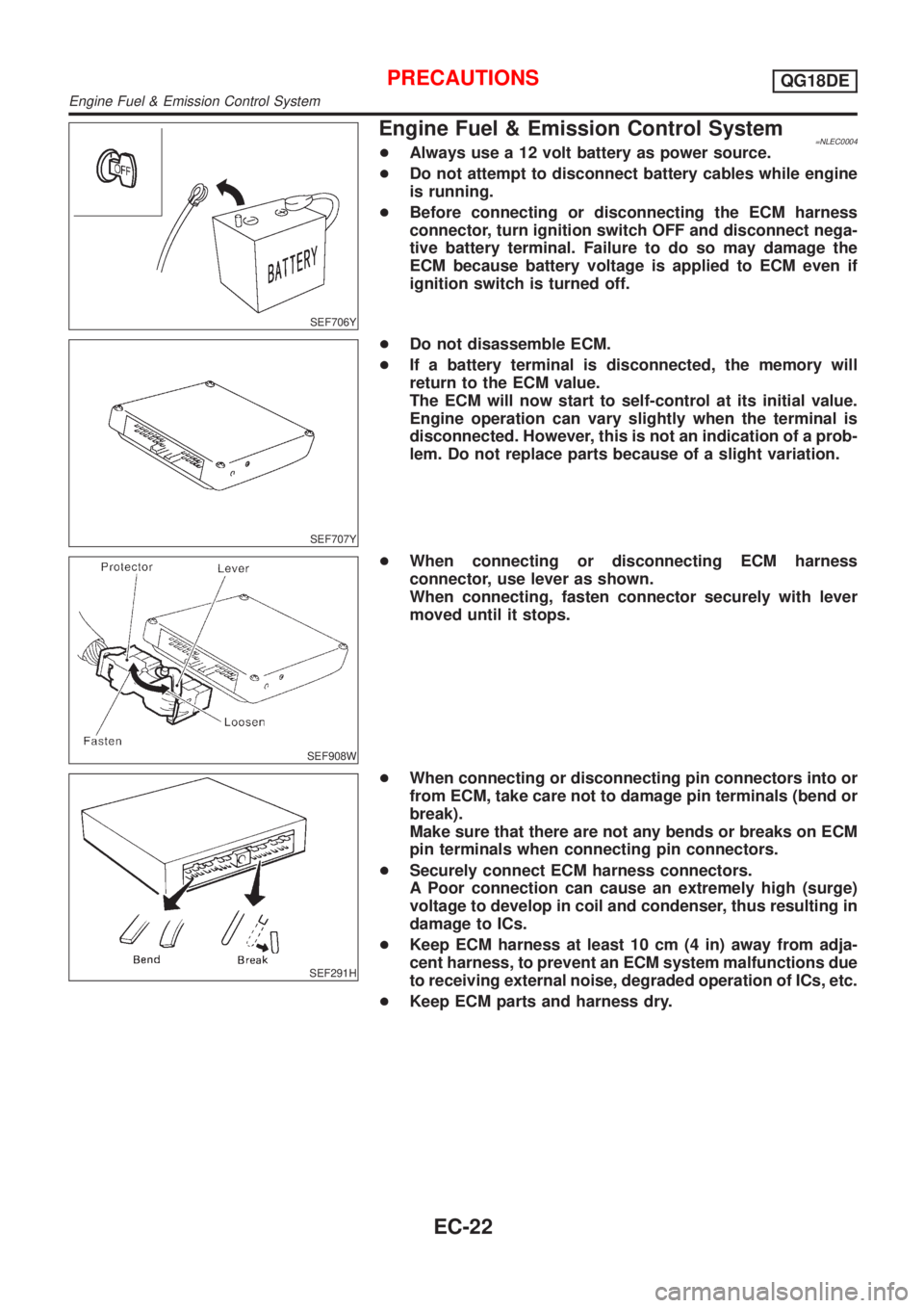
Engine Fuel & Emission Control System=NLEC0004+Always use a 12 volt battery as power source.
+Do not attempt to disconnect battery cables while engine
is running.
+Before connecting or disconnecting the ECM harness
connector, turn ignition switch OFF and disconnect nega-
tive battery terminal. Failure to do so may damage the
ECM because battery voltage is applied to ECM even if
ignition switch is turned off.
SEF707Y
+Do not disassemble ECM.
+If a battery terminal is disconnected, the memory will
return to the ECM value.
The ECM will now start to self-control at its initial value.
Engine operation can vary slightly when the terminal is
disconnected. However, this is not an indication of a prob-
lem. Do not replace parts because of a slight variation.
SEF908W
+When connecting or disconnecting ECM harness
connector, use lever as shown.
When connecting, fasten connector securely with lever
moved until it stops.
SEF291H
+When connecting or disconnecting pin connectors into or
from ECM, take care not to damage pin terminals (bend or
break).
Make sure that there are not any bends or breaks on ECM
pin terminals when connecting pin connectors.
+Securely connect ECM harness connectors.
A Poor connection can cause an extremely high (surge)
voltage to develop in coil and condenser, thus resulting in
damage to ICs.
+Keep ECM harness at least 10 cm (4 in) away from adja-
cent harness, to prevent an ECM system malfunctions due
to receiving external noise, degraded operation of ICs, etc.
+Keep ECM parts and harness dry.
PRECAUTIONSQG18DE
Engine Fuel & Emission Control System
EC-22
Page 459 of 3051
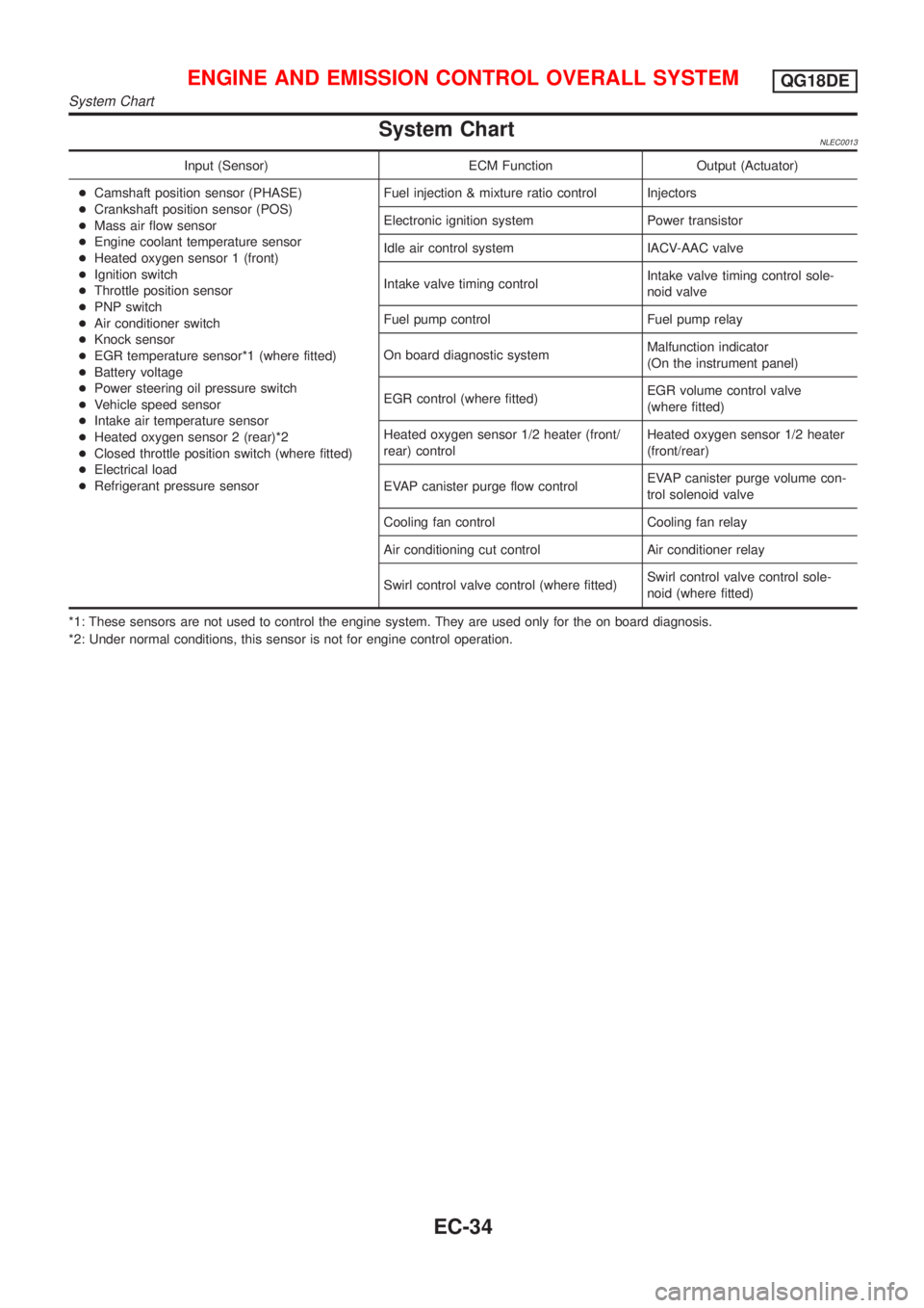
System ChartNLEC0013
Input (Sensor) ECM Function Output (Actuator)
+Camshaft position sensor (PHASE)
+Crankshaft position sensor (POS)
+Mass air flow sensor
+Engine coolant temperature sensor
+Heated oxygen sensor 1 (front)
+Ignition switch
+Throttle position sensor
+PNP switch
+Air conditioner switch
+Knock sensor
+EGR temperature sensor*1 (where fitted)
+Battery voltage
+Power steering oil pressure switch
+Vehicle speed sensor
+Intake air temperature sensor
+Heated oxygen sensor 2 (rear)*2
+Closed throttle position switch (where fitted)
+Electrical load
+Refrigerant pressure sensorFuel injection & mixture ratio control Injectors
Electronic ignition system Power transistor
Idle air control system IACV-AAC valve
Intake valve timing controlIntake valve timing control sole-
noid valve
Fuel pump control Fuel pump relay
On board diagnostic systemMalfunction indicator
(On the instrument panel)
EGR control (where fitted)EGR volume control valve
(where fitted)
Heated oxygen sensor 1/2 heater (front/
rear) controlHeated oxygen sensor 1/2 heater
(front/rear)
EVAP canister purge flow controlEVAP canister purge volume con-
trol solenoid valve
Cooling fan control Cooling fan relay
Air conditioning cut control Air conditioner relay
Swirl control valve control (where fitted)Swirl control valve control sole-
noid (where fitted)
*1: These sensors are not used to control the engine system. They are used only for the on board diagnosis.
*2: Under normal conditions, this sensor is not for engine control operation.
ENGINE AND EMISSION CONTROL OVERALL SYSTEMQG18DE
System Chart
EC-34
Page 460 of 3051
Multiport Fuel Injection (MFI) System
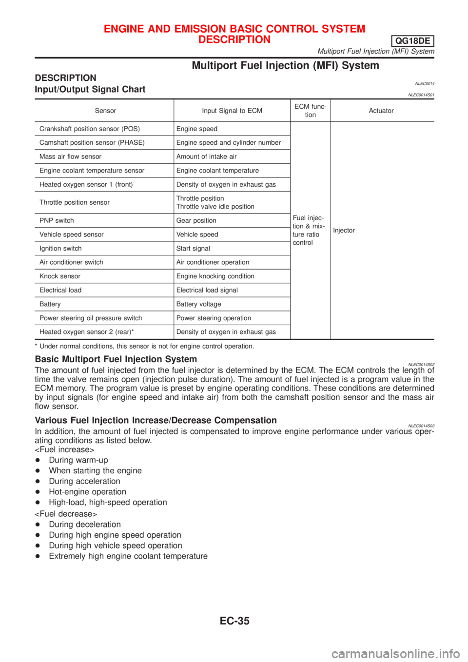
DESCRIPTIONNLEC0014Input/Output Signal ChartNLEC0014S01
Sensor Input Signal to ECMECM func-
tionActuator
Crankshaft position sensor (POS) Engine speed
Fuel injec-
tion & mix-
ture ratio
controlInjector Camshaft position sensor (PHASE) Engine speed and cylinder number
Mass air flow sensor Amount of intake air
Engine coolant temperature sensor Engine coolant temperature
Heated oxygen sensor 1 (front) Density of oxygen in exhaust gas
Throttle position sensorThrottle position
Throttle valve idle position
PNP switch Gear position
Vehicle speed sensor Vehicle speed
Ignition switch Start signal
Air conditioner switch Air conditioner operation
Knock sensor Engine knocking condition
Electrical load Electrical load signal
Battery Battery voltage
Power steering oil pressure switch Power steering operation
Heated oxygen sensor 2 (rear)* Density of oxygen in exhaust gas
* Under normal conditions, this sensor is not for engine control operation.
Basic Multiport Fuel Injection SystemNLEC0014S02The amount of fuel injected from the fuel injector is determined by the ECM. The ECM controls the length of
time the valve remains open (injection pulse duration). The amount of fuel injected is a program value in the
ECM memory. The program value is preset by engine operating conditions. These conditions are determined
by input signals (for engine speed and intake air) from both the camshaft position sensor and the mass air
flow sensor.
Various Fuel Injection Increase/Decrease CompensationNLEC0014S03In addition, the amount of fuel injected is compensated to improve engine performance under various oper-
ating conditions as listed below.
+During warm-up
+When starting the engine
+During acceleration
+Hot-engine operation
+High-load, high-speed operation
+During deceleration
+During high engine speed operation
+During high vehicle speed operation
+Extremely high engine coolant temperature
ENGINE AND EMISSION BASIC CONTROL SYSTEM
DESCRIPTION
QG18DE
Multiport Fuel Injection (MFI) System
EC-35
Page 462 of 3051
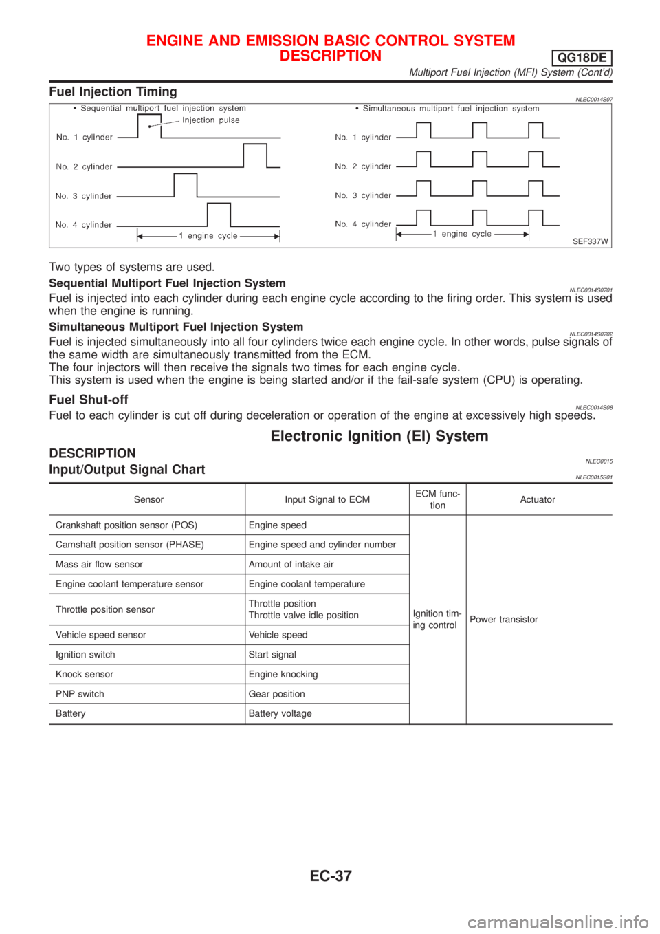
Fuel Injection TimingNLEC0014S07
SEF337W
Two types of systems are used.
Sequential Multiport Fuel Injection System
NLEC0014S0701Fuel is injected into each cylinder during each engine cycle according to the firing order. This system is used
when the engine is running.
Simultaneous Multiport Fuel Injection System
NLEC0014S0702Fuel is injected simultaneously into all four cylinders twice each engine cycle. In other words, pulse signals of
the same width are simultaneously transmitted from the ECM.
The four injectors will then receive the signals two times for each engine cycle.
This system is used when the engine is being started and/or if the fail-safe system (CPU) is operating.
Fuel Shut-offNLEC0014S08Fuel to each cylinder is cut off during deceleration or operation of the engine at excessively high speeds.
Electronic Ignition (EI) System
DESCRIPTIONNLEC0015Input/Output Signal ChartNLEC0015S01
Sensor Input Signal to ECMECM func-
tionActuator
Crankshaft position sensor (POS) Engine speed
Ignition tim-
ing controlPower transistor Camshaft position sensor (PHASE) Engine speed and cylinder number
Mass air flow sensor Amount of intake air
Engine coolant temperature sensor Engine coolant temperature
Throttle position sensorThrottle position
Throttle valve idle position
Vehicle speed sensor Vehicle speed
Ignition switch Start signal
Knock sensor Engine knocking
PNP switch Gear position
Battery Battery voltage
ENGINE AND EMISSION BASIC CONTROL SYSTEM
DESCRIPTION
QG18DE
Multiport Fuel Injection (MFI) System (Cont'd)
EC-37