2001 NISSAN ALMERA TINO service
[x] Cancel search: servicePage 2692 of 3051
SHA708EA
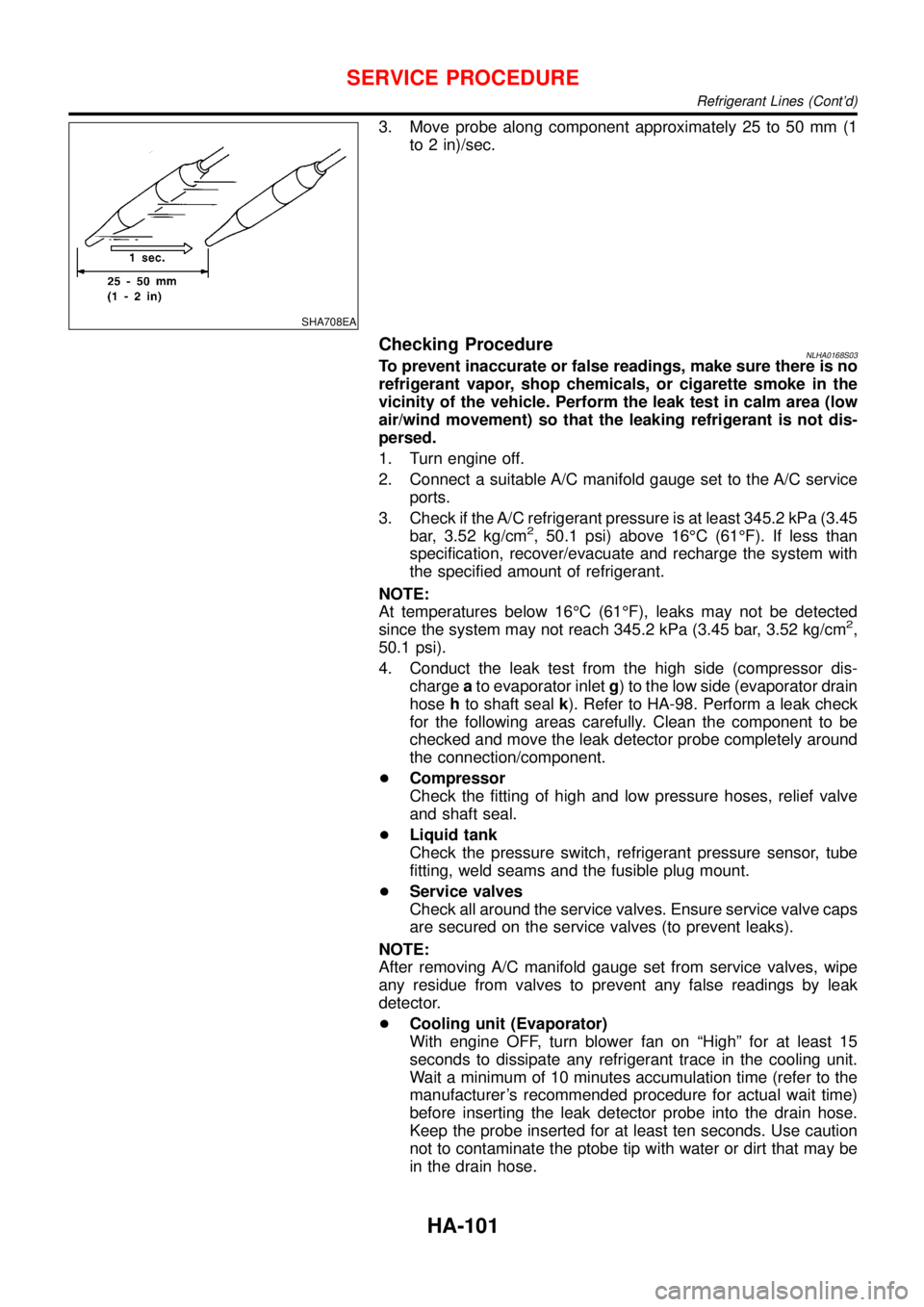
3. Move probe along component approximately 25 to 50 mm (1
to 2 in)/sec.
Checking ProcedureNLHA0168S03To prevent inaccurate or false readings, make sure there is no
refrigerant vapor, shop chemicals, or cigarette smoke in the
vicinity of the vehicle. Perform the leak test in calm area (low
air/wind movement) so that the leaking refrigerant is not dis-
persed.
1. Turn engine off.
2. Connect a suitable A/C manifold gauge set to the A/C service
ports.
3. Check if the A/C refrigerant pressure is at least 345.2 kPa (3.45
bar, 3.52 kg/cm
2, 50.1 psi) above 16°C (61°F). If less than
specification, recover/evacuate and recharge the system with
the specified amount of refrigerant.
NOTE:
At temperatures below 16°C (61°F), leaks may not be detected
since the system may not reach 345.2 kPa (3.45 bar, 3.52 kg/cm
2,
50.1 psi).
4. Conduct the leak test from the high side (compressor dis-
chargeato evaporator inletg) to the low side (evaporator drain
hosehto shaft sealk). Refer to HA-98. Perform a leak check
for the following areas carefully. Clean the component to be
checked and move the leak detector probe completely around
the connection/component.
+Compressor
Check the fitting of high and low pressure hoses, relief valve
and shaft seal.
+Liquid tank
Check the pressure switch, refrigerant pressure sensor, tube
fitting, weld seams and the fusible plug mount.
+Service valves
Check all around the service valves. Ensure service valve caps
are secured on the service valves (to prevent leaks).
NOTE:
After removing A/C manifold gauge set from service valves, wipe
any residue from valves to prevent any false readings by leak
detector.
+Cooling unit (Evaporator)
With engine OFF, turn blower fan on“High”for at least 15
seconds to dissipate any refrigerant trace in the cooling unit.
Wait a minimum of 10 minutes accumulation time (refer to the
manufacturer’s recommended procedure for actual wait time)
before inserting the leak detector probe into the drain hose.
Keep the probe inserted for at least ten seconds. Use caution
not to contaminate the ptobe tip with water or dirt that may be
in the drain hose.
SERVICE PROCEDURE
Refrigerant Lines (Cont’d)
HA-101
Page 2693 of 3051
5. If a leak detector detects a leak, verify at least once by blow-
ing compressed air into area of suspected leak, then repeat
check as outlined above.
6. Do not stop when one leak is found. Continue to check for
additional leaks at all system components.
If no leaks are found, perform steps7-10.
7. Start engine.
8. Set the heater A/C control as follows:
1) A/C switch ON.
2) Face mode
3) Recirculation position
4) Max cold temperature
5) Fan speed high
9. Run engine at 1,500 rpm for at least 2 minutes.
10. Turn engine off and perform leak check again following steps
4 through 6 above.
SHA839E
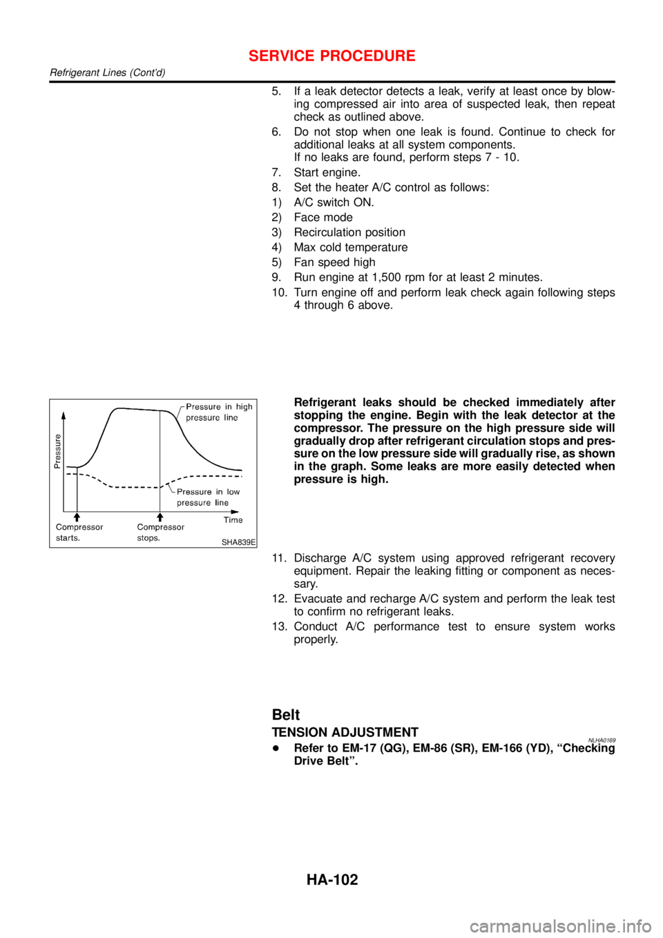
Refrigerant leaks should be checked immediately after
stopping the engine. Begin with the leak detector at the
compressor. The pressure on the high pressure side will
gradually drop after refrigerant circulation stops and pres-
sure on the low pressure side will gradually rise, as shown
in the graph. Some leaks are more easily detected when
pressure is high.
11. Discharge A/C system using approved refrigerant recovery
equipment. Repair the leaking fitting or component as neces-
sary.
12. Evacuate and recharge A/C system and perform the leak test
to confirm no refrigerant leaks.
13. Conduct A/C performance test to ensure system works
properly.
Belt
TENSION ADJUSTMENTNLHA0169+Refer to EM-17 (QG), EM-86 (SR), EM-166 (YD),“Checking
Drive Belt”.
SERVICE PROCEDURE
Refrigerant Lines (Cont’d)
HA-102
Page 2697 of 3051
A
A/C HFC134a (R134a) system precaution . HA-2
A/C HFC134a (R134a) system service
procedure .............................................. HA-85
A/C HFC134a (R134a) system service
tools ....................................................... HA-10
A/C HFC134a system service equip-
ment precaution ....................................... HA-6
A/C air flow ............................................... HA-19
A/C component layout .............................. HA-17
A/C compressor clutch removal and
installation .............................................. HA-90
A/C compressor precaution ........................ HA-5
A/C compressor special service tool .......... HA-9
A/C control linkage adjustment
(manual A/C) ......................................... HA-48
A/C control operation (manual A/C) .......... HA-18
A/C diagnostic work flow (manual
A/C) ...................................................... HA-40
A/C harness layout (manual A/C) ............. HA-21
A/C lubricant (R134a) ............................... HA-87
A/C operational check ............................... HA-41
A/C performance chart .............................. HA-78
A/C performance test diagnoses .............. HA-76
A/C relay ................................................... HA-73
A/C service data specification ................ HA-104
A/C switch ................................................. HA-74
A/C, M - Wiring diagram ........................... HA-27
A/CCUT - Wiring diagram ..................... EC-1301
A/T - Wiring diagram - AT - BA/FTS ........ AT-172
A/T - Wiring diagram - AT - ENG SS ........ AT-91,
177
A/T - Wiring diagram - AT - FTS ................ AT-75
A/T - Wiring diagram - AT - LPSV ... AT-101, 159
A/T - Wiring diagram - AT - MAIN ............. AT-62
A/T - Wiring diagram - AT - PNP/SW ........ AT-68
A/T - Wiring diagram - AT - SSV/A .......... AT-147
A/T - Wiring diagram - AT - TCV ....... AT-96, 166
A/T - Wiring diagram - AT - TPS ..... AT-106, 139
A/T - Wiring diagram - AT - VSS/AT .. AT-86, 128
A/T - Wiring diagram - AT -
VSSMTR .............................................. AT-134
A/T control ............................................. EC-1012
A/T diagnosis communication line .......... EC-928
A/T shift lock system - Wiring
diagram ................................................ AT-196
A/T shift lock system ................................ AT-195
A/T trouble diagnoses .......................... AT-41, 46
AAC/V - Wiring diagram . EC-345, 468, 865, 997
ABS (anti-lock brake system) ................... BR-42
ABS - Wiring diagram ............................... BR-48
ABS sensor rotor ....................................... AX-23
APS - Wiring diagram ........................... EC-1155
AT/C - Wiring diagram .......................... EC-1013
ATDIAG - Wiring diagram ....................... EC-929
Accelerator control system .................... FE-3, 14
Accelerator position sensor ................... EC-1155
Air bag disposal ........................................ RS-30Air bag precautions .................................. GI-3
Air bag ....................................................... RS-16
Air bleeding (hydraulic clutch) ................... CL-10
Air bleeding for brake system ..................... BR-8
Air conditioner cut control ....... EC-38, 572, 1081
Air flow meter - See Mass air flow
sensor ................................ EC-154, 679, 1143
Air mix door control linkage
adjustment ............................................. HA-50
Air spoiler, rear .......................................... BT-38
Alternator ................................................... SC-28
Angular tightening application ...... EM-5, 76, 158
Antenna - See Power antenna ................ EL-233
Anti-lock brake system - Wiring
diagram .................................................. BR-48
Audio and A/C control removal and
installation - See Instrument panel ........ BT-22
Audio ........................................................ EL-208
Automatic transaxle number ...................... GI-40
Auxiliary air control (AAC) valve .... EC-343, 466,
863, 995
B
Back-up lamp switch (M/T) ....................... MT-16
Back-up lamp ............................................. EL-93
Ball joint (front) .......................................... SU-13
Basic inspection ...................... EC-99, 623,1111
Battery ......................................................... SC-3
Baulk ring (M/T) .................................. MT-25, 63
Blower motor ............................................. HA-61
Blower resistor .......................................... HA-61
Board-on lift ................................................ GI-42
Body alignment .......................................... BT-65
Brake booster ............................................ BR-16
Brake fluid change ...................................... BR-7
Brake fluid level and line check .................. BR-7
Brake hydraulic line .................................... BR-9
Brake pedal ............................................... BR-11
Bulb specifications ................................... EL-524
Bumper, front .............................................. BT-7
Bumper, rear .............................................. BT-10
C
CHARGE - Wiring diagram ....................... SC-25
CHIME - Wiring diagram ......................... EL-166
CIGAR - Wiring diagram ......................... EL-195
CKPS - Wiring diagram . EC-297, 440, 821, 911,
970, 1166
CMPS - Wiring diagram .................. EC-304, 828
CONSULT for ABS .................................... BR-58
CONSULT for engine .............. EC-82, 607, 1102
COOL/F - Wiring diagram ..... EC-376, 885, 1201
Camshaft inspection ................. EM-36, 114, 204
Camshaft position sensor (CMPS) . EC-302, 825
Camshaft position sensor (PHASE) ........ EC-302
ALPHABETICAL INDEX
IDX-2
Page 2698 of 3051
Canister - See EVAP canister .......... EC-39, 573
Charging system ....................................... SC-24
Cigarette lighter ....................................... EL-195
Circuit breaker ........................................... EL-32
Closed throttle position switch ....... EC-352, 872
Clutch cover .............................................. CL-22
Clutch disc ................................................. CL-22
Clutch master cylinder ............................... CL-11
Clutch operating cylinder ........................... CL-14
Clutch pedal .............................................. CL-10
Clutch release bearing ........................ CL-17, 20
Clutch release mechanism .................. CL-17, 20
Clutch withdrawal lever ....................... CL-17, 20
Coil spring (front) ...................................... SU-10
Coil spring (rear) ....................................... SU-23
Collision diagnosis .................................... RS-66
Combination lamp, rear, removal and
installation .............................................. BT-38
Combination meter removal and instal-
lation - See Instrument panel ................ BT-22
Combination meter .................................. EL-130
Combination switch ................................... EL-64
Compression pressure ........................... EM-164
Compressor clutch removal and
installation .............................................. HA-90
Compressor precaution ............................... HA-5
Compressor special service tool ................. HA-9
Connecting rod bearing clearance .. EM-58, 140,
232
Connecting rod bushing clearance .. EM-59, 141,
234
Connecting rod ......................... EM-55, 136, 227
Console box - See Instrument panel ......... BT-22
Control lever (M/T) .................................... MT-23
Converter housing installation ................. AT-207
Coolant mixture ratio ................................ MA-22
Cooling circuit (engine) ................. LC-12, 32, 53
Cooling fan control system ........................ LC-59
Cooling fan control ............... EC-373, 882, 1201
Cooling fan motor ........................... EC-385, 899
Cooling fan relay ............................. EC-384, 898
Coupling sleeve (M/T) ........................ MT-25, 63
Crank angle sensor built into distribu-
tor - See Camshaft position
sensor .................................................. EC-825
Crankcase emission control system -
See Positive crankcase ventilation ...... EC-42,
576, 1082
Crankcase ventilation system - See
Positive crankcase ventilation ...... EC-42, 576,
1082
Crankshaft position sensor (OBD) . EC-295, 439,
819, 969
Crankshaft position sensor (POS) .. EC-295, 439
Crankshaft position sensor (TDC) ......... EC-1166
Crankshaft ................................ EM-57, 138, 229
Cylinder block ........................... EM-52, 133, 221
Cylinder head ........................... EM-33, 108, 200D
DEF - Wiring diagram .............................. EL-199
DTC work support ............................. EC-91, 615
Data link connector for Consult ....... EC-43, 577,
1102
Daytime light system ................................. EL-73
Detonation sensor - See Knock
sensor .......................................... EC-291, 815
Diagnosis sensor unit ............................... RS-21
Diagnostic trouble code (DTC) for
OBD system ................... EC-16, 70, 550, 595,
1064, 1096
Diagnostic trouble code (DTC) inspec-
tion priority chart ......................... EC-122, 646
Differential gear (FF M/T) ............. MT-25, 63, 77
Dimensions ................................................. GI-41
Dome light - See Interior lamp ................ EL-116
Door glass ................................................. BT-14
Door lock ................................................... BT-18
Door mirror ................................................ BT-63
Door trim .................................................... BT-32
Door, front .................................................. BT-13
Door, rear ................................................... BT-13
Drive plate runout ..................... EM-60, 142, 235
Drive shaft (front) ...................................... AX-10
Dropping resistor (A/T) .................... AT-103, 163
Dual pressure switch ................................ HA-12
E
ECCS-D control module ... EC-1129, 1177, 1185,
1253, 1255, 1260, 1262
ECM input/output signal ........ EC-133, 657, 1129
ECTS - Wiring diagram ......... EC-171, 696, 1150
EGR control valve ................................... EC-400
EGR temperature sensor ................ EC-386, 915
EGR volume control valve ............ EC-319, 1277
EGR/TS - Wiring diagram ............... EC-389, 918
EGRC/V - Wiring diagram ....................... EC-322
EGRC1 - Wiring diagram ....... EC-314, 397, 449,
838, 925, 978, 1279
EVAP canister purge volume control
solenoid valve ............................... EC-40, 574
EVAP canister purge volume control
valve ............................ EC-332, 458, 852, 986
EVAP canister ................................... EC-40, 574
Electric sunroof ........................................ EL-238
Electrical diagnoses ................................... GI-21
Electrical ignition system .................. EC-37, 571
Electrical load signal circuit .......... EC-535, 1050
Electrical unit ........................................... EL-530
Electrical units location ............................ EL-442
Electronic fuel injection pump .... EC-1087, 1187,
1194, 1218, 1225, 1232, 1239, 1246, 1264
Engine compartment ................................. BT-66
Engine control circuit diagram ......... EC-30, 564,
1074
ALPHABETICAL INDEX
IDX-3
Page 2699 of 3051
Engine control component parts
location ................................ EC-26, 560, 1071
Engine control module (ECM) ........ EC-358, 880
Engine control system diagram and
chart .................................... EC-32, 566, 1076
Engine coolant temperature sensor
(ECTS) .............................. EC-169, 694, 1150
Engine fail-safe system .................. EC-123, 647
Engine oil precautions .................................. GI-7
Engine outer component parts ........... EM-12, 82
Engine removal ........................ EM-49, 130, 218
Engine room - See Engine
compartment .......................................... BT-66
Engine serial number ................................. GI-39
Evaporative emission (EVAP)
system ........................................... EC-39, 573
Exhaust gas recirculation (EGR)
valve ........... EC-310, 393, 446, 834, 921, 975
Exhaust system ................................... FE-11, 23
Exterior ...................................................... BT-38
F
F/PUMP - Wiring diagram ............. EC-518, 1034
FR02 - Wiring diagram .. EC-187, 207, 216, 415,
712, 732, 741, 945
FR02/H - Wiring diagram ............... EC-223, 422,
748, 952
FUEL - Wiring diagram ... EC-271, 279, 794, 802
Fan switch ................................................. HA-61
Final drive (FF M/T) ...................... MT-47, 63, 77
Finisher, interior - See Trim ....................... BT-28
Finisher, trunk lid ....................................... BT-31
Floor trim ................................................... BT-28
Fluids ........................................................ MA-20
Flywheel (clutch) ....................................... CL-22
Flywheel runout ........................ EM-60, 142, 235
Fog lamp, front, removal and
installation ................................................ BT-7
Fog lamp, front .......................................... EL-95
Fork rod (M/T) ..................................... MT-26, 64
Freeze frame data .............. EC-61, 71, 585, 596
Front axle .................................................... AX-2
Front bumper ............................................... BT-7
Front combination lamp removal and
installation ................................................ BT-7
Front disc brake ........................................ BR-24
Front door .................................................. BT-13
Front fog lamp removal and
installation ................................................ BT-7
Front fog lamp ........................................... EL-95
Front heated oxygen sensor (HO2S)
heater .......................... EC-221, 421, 746, 951
Front heated oxygen sensor (HO2S) ..... EC-184,
192, 198, 204, 214, 414, 709,
717, 723, 729, 739, 944Front seat belt ............................................. RS-5
Front seat .................................................. BT-46
Front suspension ........................................ SU-2
Front washer ............................................ EL-176
Front wiper ............................................... EL-176
Fuel cut control (at no load & high
engine speed) ..................... EC-39, 573, 1081
Fuel gauge ............................................... EL-130
Fuel injection system ............. EC-269, 277, 792,
800, 1079
Fuel injector .................................. EC-494, 1021
Fuel precautions ........................................... GI-8
Fuel pressure check ......................... EC-43, 577
Fuel pressure regulator .................... EC-44, 578
Fuel pressure release ....................... EC-43, 577
Fuel pump relay ............................ EC-516, 1032
Fuel pump ..................................... EC-516, 1032
Fuel system ........................................... FE-5, 15
Fuel tank vacuum relief valve ........... EC-40, 574
Fuse block ............................................... EL-527
Fuse ........................................................... EL-32
Fusible link ................................................. EL-32G
GLOW - Wiring diagram ....................... EC-1267
Garage jack and safety stand .................... GI-43
Gauges .................................................... EL-130
Gear components (M/T) ..................... MT-25, 63
Generator - See Alternator ....................... SC-28
Generic scan tool (GST) ................... EC-93, 617
Glass .......................................................... BT-14
Glow plug .............................................. EC-1267
Glow relay ............................................. EC-1267
Grease ...................................................... MA-20
Ground distribution .............................. EL-33, 48
H
H/LAMP - Wiring diagram .......................... EL-69
HEATER - Wiring diagram ........................ HA-23
HFC134a (R134a) system
precaution ................................................ HA-2
HFC134a (R134a) system service
procedure .............................................. HA-85
HFC134a (R134a) system service
tools ....................................................... HA-10
HFC134a system service equipment
precaution ................................................ HA-6
HORN - Wiring diagram .......................... EL-193
HSEAT - Wiring diagram ......................... EL-234
Harness connector ...................................... EL-5
Harness layout ......................................... EL-452
Hazard warning lamp .............................. EL-101
Headlamp removal and installation ............. BT-7
Headlamp washer .................................... EL-190
ALPHABETICAL INDEX
IDX-4
Page 2704 of 3051
ENGINE LUBRICATION &
COOLING SYSTEMS
SECTION
LC
CONTENTS
QG
ENGINE LUBRICATION SYSTEM..................................3
Precautions ..................................................................3
LIQUID GASKET APPLICATION PROCEDURE............3
Preparation ..................................................................3
SPECIAL SERVICE TOOLS........................................3
Lubrication Circuit ........................................................4
Oil Pressure Check......................................................5
Oil Pump ......................................................................5
REMOVAL AND INSTALLATION.................................5
DISASSEMBLY AND ASSEMBLY................................6
INSPECTION.............................................................7
REGULATOR VALVE INSPECTION............................7
Changing Engine Oil....................................................8
Changing Oil Filter .......................................................9
Service Data and Specifications (SDS).....................10
OIL PRESSURE CHECK..........................................10
OIL PUMP INSPECTION..........................................10
REGULATOR VALVE INSPECTION..........................10
OIL CAPACITY........................................................10
ENGINE COOLING SYSTEM........................................ 11
Precautions ................................................................ 11
LIQUID GASKET APPLICATION PROCEDURE.......... 11
Preparation ................................................................ 11
SPECIAL SERVICE TOOLS...................................... 11
Cooling Circuit ...........................................................12
System Check............................................................12
CHECKING COOLING SYSTEM HOSES...................12
CHECKING RADIATOR............................................13
CHECKING RADIATOR CAP....................................13
CHECKING COOLING SYSTEM FOR LEAKS............13
Water Pump ...............................................................14
REMOVAL AND INSTALLATION...............................14
INSPECTION...........................................................14
Thermostat .................................................................15
REMOVAL AND INSTALLATION...............................15
INSPECTION...........................................................16
Radiator .....................................................................17
COMPONENTS.......................................................17
Cooling Fan ...............................................................18
COMPONENTS.......................................................18
CONTROL SYSTEM................................................19
Changing Engine Coolant..........................................19
- DRAINING ENGINE COOLANT -............................19
- REFILLING ENGINE COOLANT -...........................20
- FLUSHING COOLING SYSTEM -............................20
Overheating Cause Analysis .....................................21
Service Data and Specifications (SDS).....................22
THERMOSTAT........................................................22
RADIATOR..............................................................22
COOLANT CAPACITY..............................................22
SR
ENGINE LUBRICATION SYSTEM................................23
Precautions ................................................................23
LIQUID GASKET APPLICATION PROCEDURE..........23
Preparation ................................................................23
SPECIAL SERVICE TOOLS......................................23
Lubrication Circuit ......................................................24
Oil Pressure Check....................................................25
Oil Pump ....................................................................25
REMOVAL AND INSTALLATION...............................25
DISASSEMBLY AND ASSEMBLY..............................26
INSPECTION...........................................................26
REGULATOR VALVE INSPECTION..........................27
Changing Engine Oil..................................................28
Changing Engine Oil Filter ........................................28
Oil Filter .....................................................................29
Oil Cooler ...................................................................29
REMOVAL AND INSTALLATION...............................29
INSPECTION...........................................................30
Service Data and Specifications (SDS).....................30
OIL PRESSURE CHECK..........................................30
REGULATOR VALVE INSPECTION..........................30
OIL PUMP INSPECTION..........................................30
OIL CAPACITY........................................................30
ENGINE COOLING SYSTEM........................................31
Precautions ................................................................31
LIQUID GASKET APPLICATION PROCEDURE..........31
Preparation ................................................................31
Page 2705 of 3051
SPECIAL SERVICE TOOL........................................31
Cooling Circuit ...........................................................32
System Check............................................................32
CHECKING COOLING SYSTEM HOSES...................32
CHECKING COOLING SYSTEM FOR LEAKS............32
CHECKING RADIATOR............................................33
CHECKING RADIATOR CAP....................................33
Water Pump ...............................................................33
REMOVAL AND INSTALLATION...............................33
INSPECTION...........................................................34
Thermostat .................................................................35
REMOVAL AND INSTALLATION...............................35
INSPECTION...........................................................36
Water Outlet ...............................................................36
INSPECTION...........................................................36
INSTALLATION........................................................36
Radiator .....................................................................37
COMPONENTS.......................................................37
Cooling Fan Control System .....................................37
Changing Engine Coolant..........................................38
- DRAINING ENGINE COOLANT -............................38
- REFILLING ENGINE COOLANT -...........................38
- FLUSHING COOLING SYSTEM -............................39
Overheating Cause Analysis .....................................40
Service Data and Specifications (SDS).....................41
THERMOSTAT........................................................41
RADIATOR..............................................................41
COOLANT CAPACITY..............................................41
YD
ENGINE LUBRICATION SYSTEM................................42
Precautions ................................................................42
LIQUID GASKET APPLICATION PROCEDURE..........42
Preparation ................................................................42
SPECIAL SERVICE TOOLS......................................42
Lubrication Circuit ......................................................43
Oil Pressure Check....................................................44
Oil Pump ....................................................................44
REMOVAL AND INSTALLATION...............................44
DISASSEMBLY AND ASSEMBLY..............................45
OIL PUMP INSPECTION..........................................45
REGULATOR VALVE INSPECTION..........................46
Changing Engine Oil..................................................47
Oil Filter Bracket ........................................................48
REMOVAL AND INSTALLATION...............................48
Changing Oil Filter .....................................................48
REMOVAL...............................................................49
INSTALLATION........................................................49
Oil Cooler ...................................................................50
REMOVAL AND INSTALLATION...............................50
Service Data and Specifications (SDS).....................51
OIL PRESSURE CHECK..........................................51
REGULATOR VALVE INSPECTION..........................51
OIL PUMP INSPECTION..........................................51
ENGINE OIL CAPACITY...........................................51
ENGINE COOLING SYSTEM........................................52
Precautions ................................................................52
LIQUID GASKET APPLICATION PROCEDURE..........52
Preparation ................................................................52
SPECIAL SERVICE TOOLS......................................52
Cooling Circuit ...........................................................53
System Check............................................................54
CHECKING COOLING SYSTEM HOSES...................54
CHECKING RADIATOR............................................54
CHECKING RADIATOR CAP....................................54
CHECKING COOLING SYSTEM FOR LEAKS............55
Water Pump ...............................................................55
REMOVAL AND INSTALLATION...............................55
REMOVAL...............................................................56
INSPECTION...........................................................56
INSTALLATION........................................................56
Thermostat .................................................................57
REMOVAL AND INSTALLATION...............................57
INSPECTION...........................................................58
Radiator .....................................................................58
COMPONENTS.......................................................58
REMOVAL AND INSTALLATION...............................59
Cooling Fan ...............................................................59
COMPONENTS.......................................................59
CONTROL SYSTEM................................................59
Changing Engine Coolant..........................................59
- DRAINING ENGINE COOLANT -............................59
- REFILLING ENGINE COOLANT -...........................60
- FLUSHING COOLING SYSTEM -............................61
Overheating Cause Analysis .....................................62
Service Data and Specifications (SDS).....................63
THERMOSTAT........................................................63
RADIATOR..............................................................63
ENGINE COOLANT CAPACITY................................63
CONTENTS(Cont'd)
LC-2
Page 2706 of 3051
SEM164F
AEM080
Precautions
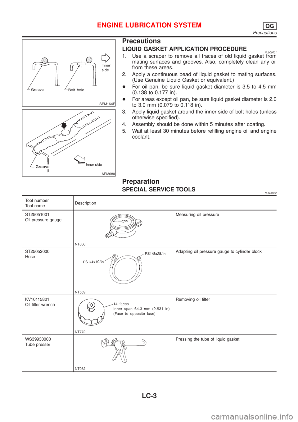
LIQUID GASKET APPLICATION PROCEDURENLLC00011. Use a scraper to remove all traces of old liquid gasket from
mating surfaces and grooves. Also, completely clean any oil
from these areas.
2. Apply a continuous bead of liquid gasket to mating surfaces.
(Use Genuine Liquid Gasket or equivalent.)
+For oil pan, be sure liquid gasket diameter is 3.5 to 4.5 mm
(0.138 to 0.177 in).
+For areas except oil pan, be sure liquid gasket diameter is 2.0
to 3.0 mm (0.079 to 0.118 in).
3. Apply liquid gasket around the inner side of bolt holes (unless
otherwise specified).
4. Assembly should be done within 5 minutes after coating.
5. Wait at least 30 minutes before refilling engine oil and engine
coolant.
Preparation
SPECIAL SERVICE TOOLSNLLC0002
Tool number
Tool nameDescription
ST25051001
Oil pressure gauge
NT050
Measuring oil pressure
ST25052000
Hose
NT559
Adapting oil pressure gauge to cylinder block
KV10115801
Oil filter wrench
NT772
Removing oil filter
WS39930000
Tube presser
NT052
Pressing the tube of liquid gasket
ENGINE LUBRICATION SYSTEMQG
Precautions
LC-3