2001 NISSAN ALMERA TINO battery
[x] Cancel search: batteryPage 2155 of 3051
Anti-theft System=NLEL0519RHD MODELSNLEL0519S01Description
By integrating the Navigation System in the vehicle's interior and linking it to the vehicle's immobilizer system,
the possibility of the Navigation unit being stolen is effectively reduced. Each time the Navigation System is
switched on, the Navigation System will start up communication with the vehicle's immobilizer control unit
(IMMU) and verify an identification code. If communication cannot be established, or the verified code is
incorrect, the Navigation System will lock up showing ªANTI-THEFT FUNCTIONº on the Navigation display.
The 4-digit PIN must be entered when the display shows ªenter your PINº at the time the vehicle is purchased.
The 4±digit PIN is required to input after disconnecting and reconnecting of battery cable or connectors for
Navigation system.
LHD MODELSNLEL0519S02Description
The 4-digit PIN must be entered when the display shows ªenter your PINº at the time the vehicle is purchased.
The 4±digit PIN is required to input after disconnecting and reconnecting of battery cable or connectors for
Navigation system.
NAVIGATION SYSTEM
Anti-theft System
EL-424
Page 2157 of 3051
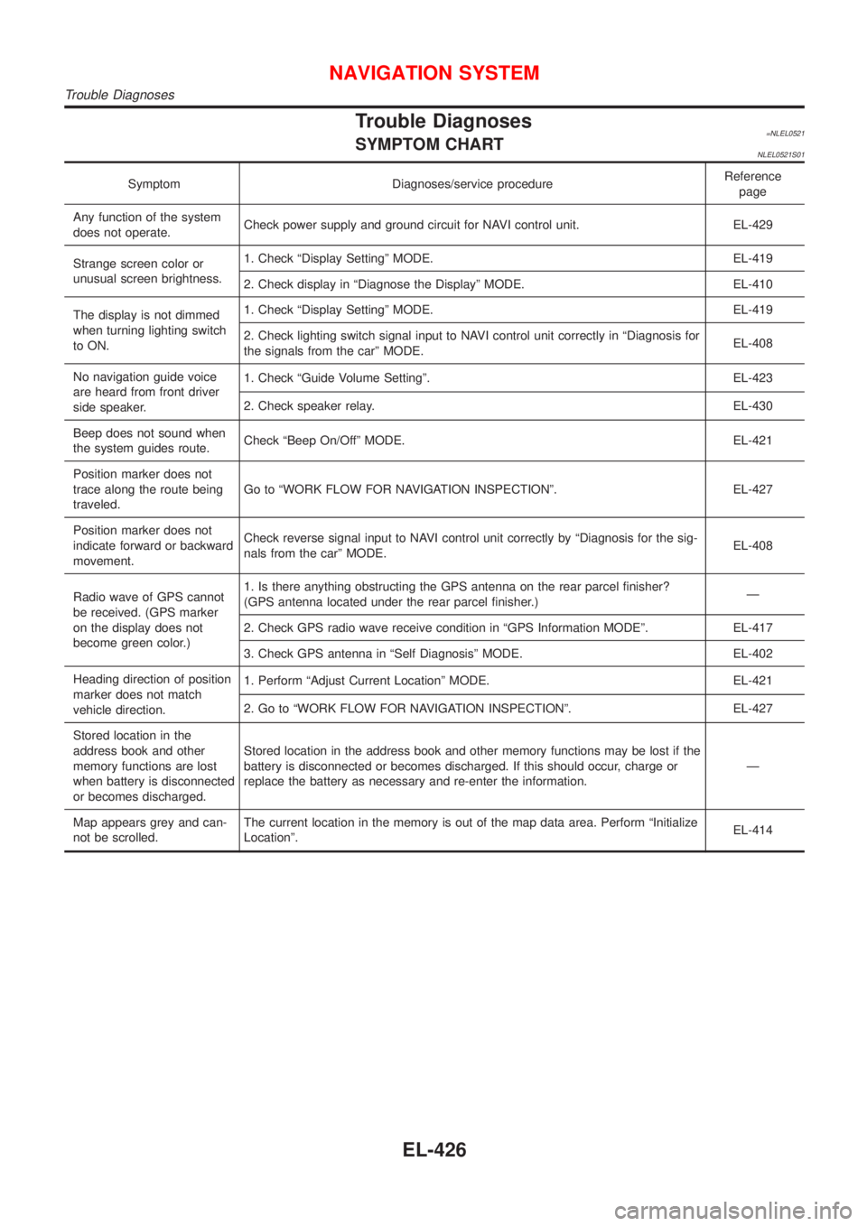
Trouble Diagnoses=NLEL0521SYMPTOM CHARTNLEL0521S01
Symptom Diagnoses/service procedureReference
page
Any function of the system
does not operate.Check power supply and ground circuit for NAVI control unit. EL-429
Strange screen color or
unusual screen brightness.1. Check ªDisplay Settingº MODE. EL-419
2. Check display in ªDiagnose the Displayº MODE. EL-410
The display is not dimmed
when turning lighting switch
to ON.1. Check ªDisplay Settingº MODE. EL-419
2. Check lighting switch signal input to NAVI control unit correctly in ªDiagnosis for
the signals from the carº MODE.EL-408
No navigation guide voice
are heard from front driver
side speaker.1. Check ªGuide Volume Settingº. EL-423
2. Check speaker relay. EL-430
Beep does not sound when
the system guides route.Check ªBeep On/Offº MODE. EL-421
Position marker does not
trace along the route being
traveled.Go to ªWORK FLOW FOR NAVIGATION INSPECTIONº. EL-427
Position marker does not
indicate forward or backward
movement.Check reverse signal input to NAVI control unit correctly by ªDiagnosis for the sig-
nals from the carº MODE.EL-408
Radio wave of GPS cannot
be received. (GPS marker
on the display does not
become green color.)1. Is there anything obstructing the GPS antenna on the rear parcel finisher?
(GPS antenna located under the rear parcel finisher.)Ð
2. Check GPS radio wave receive condition in ªGPS Information MODEº. EL-417
3. Check GPS antenna in ªSelf Diagnosisº MODE. EL-402
Heading direction of position
marker does not match
vehicle direction.1. Perform ªAdjust Current Locationº MODE. EL-421
2. Go to ªWORK FLOW FOR NAVIGATION INSPECTIONº. EL-427
Stored location in the
address book and other
memory functions are lost
when battery is disconnected
or becomes discharged.Stored location in the address book and other memory functions may be lost if the
battery is disconnected or becomes discharged. If this should occur, charge or
replace the battery as necessary and re-enter the information.Ð
Map appears grey and can-
not be scrolled.The current location in the memory is out of the map data area. Perform ªInitialize
Locationº.EL-414
NAVIGATION SYSTEM
Trouble Diagnoses
EL-426
Page 2160 of 3051
NEL705
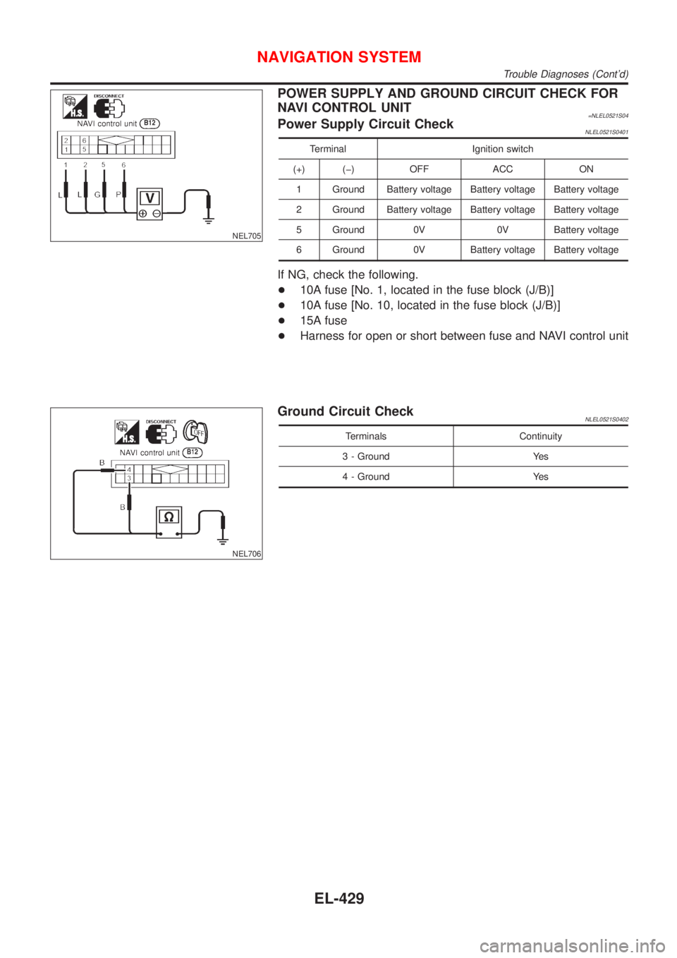
POWER SUPPLY AND GROUND CIRCUIT CHECK FOR
NAVI CONTROL UNIT
=NLEL0521S04Power Supply Circuit CheckNLEL0521S0401
Terminal Ignition switch
(+) (þ) OFF ACC ON
1 Ground Battery voltage Battery voltage Battery voltage
2 Ground Battery voltage Battery voltage Battery voltage
5 Ground 0V 0V Battery voltage
6 Ground 0V Battery voltage Battery voltage
If NG, check the following.
+10A fuse [No. 1, located in the fuse block (J/B)]
+10A fuse [No. 10, located in the fuse block (J/B)]
+15A fuse
+Harness for open or short between fuse and NAVI control unit
NEL706
Ground Circuit CheckNLEL0521S0402
Terminals Continuity
3 - Ground Yes
4 - Ground Yes
NAVIGATION SYSTEM
Trouble Diagnoses (Cont'd)
EL-429
Page 2273 of 3051
NLEM0007
1. Warm up engine.
2. Turn ignition switch OFF.
3. Release fuel pressure.
Refer to EC-43, ªReleasing Fuel Pressureº.
4. Remove ignition coils.
5. Remove spark plugs.
+Clean area around plug with compressed air before removing
the spark plug.
SEM973E
AEM308
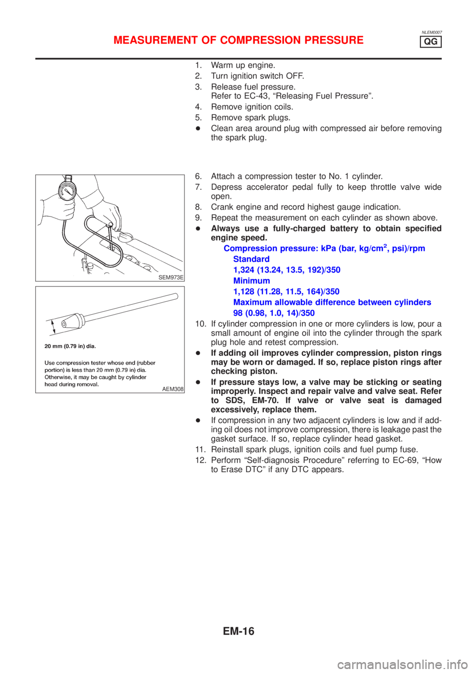
6. Attach a compression tester to No. 1 cylinder.
7. Depress accelerator pedal fully to keep throttle valve wide
open.
8. Crank engine and record highest gauge indication.
9. Repeat the measurement on each cylinder as shown above.
+Always use a fully-charged battery to obtain specified
engine speed.
Compression pressure: kPa (bar, kg/cm
2, psi)/rpm
Standard
1,324 (13.24, 13.5, 192)/350
Minimum
1,128 (11.28, 11.5, 164)/350
Maximum allowable difference between cylinders
98 (0.98, 1.0, 14)/350
10. If cylinder compression in one or more cylinders is low, pour a
small amount of engine oil into the cylinder through the spark
plug hole and retest compression.
+If adding oil improves cylinder compression, piston rings
may be worn or damaged. If so, replace piston rings after
checking piston.
+If pressure stays low, a valve may be sticking or seating
improperly. Inspect and repair valve and valve seat. Refer
to SDS, EM-70. If valve or valve seat is damaged
excessively, replace them.
+If compression in any two adjacent cylinders is low and if add-
ing oil does not improve compression, there is leakage past the
gasket surface. If so, replace cylinder head gasket.
11. Reinstall spark plugs, ignition coils and fuel pump fuse.
12. Perform ªSelf-diagnosis Procedureº referring to EC-69, ªHow
to Erase DTCº if any DTC appears.
MEASUREMENT OF COMPRESSION PRESSUREQG
EM-16
Page 2307 of 3051
WARNING:
+Position vehicle on a flat and solid surface.
+Place chocks at front and back of rear wheels.
+Do not remove engine until exhaust system has com-
pletely cooled off, otherwise, you may burn yourself
and/or fire may break out in fuel line.
+Before disconnecting fuel hose, release pressure.
Refer to EC-43, ªFuel Pressure Releaseº.
+Be sure to lift engine and transaxle in a safe manner.
+For engines not equipped with engine slingers, attach
proper slingers and bolts described in PARTS CATALOG.
CAUTION:
+When lifting engine, be sure to clear surrounding parts.
Use special care near accelerator wire casing, brake lines
and brake master cylinder.
+When lifting the engine, always use engine slingers in a
safe manner.
+When removing drive shaft, be careful not to damage
grease seal of transaxle.
+Before separating engine and transaxle, remove crank-
shaft position sensor (POS) from the cylinder block
assembly.
+Always be extra careful not to damage edge of crankshaft
position sensor (POS), or signal plate teeth.
Engine cannot be removed separately from transaxle. Remove
engine with transaxle as an assembly.
REMOVALNLEM0022S011. Drain coolant from radiator and cylinder block. Refer to LC-18,
ªChanging Engine Coolantº.
2. Remove coolant reservoir tank and bracket.
3. Drain engine oil.
4. Remove battery and battery tray.
5. Remove air cleaner and air duct.
6. Remove drive belts.
7. Remove alternator and air conditioner compressor from
engine.
8. Remove power steering oil pump from engine and position
aside.
Power steering oil pump does not need to be disconnected
from power steering tubes.
ENGINE ASSEMBLYQG
Removal and Installation (Cont'd)
EM-50
Page 2342 of 3051
NLEM0118
1. Warm up engine.
2. Turn ignition switch OFF.
3. Release fuel pressure.
Refer to EC-578, ªFuel Pressure Releaseº.
4. Remove all spark plugs.
5. Disconnect distributor coil connector.
SEM973E
SEM387C
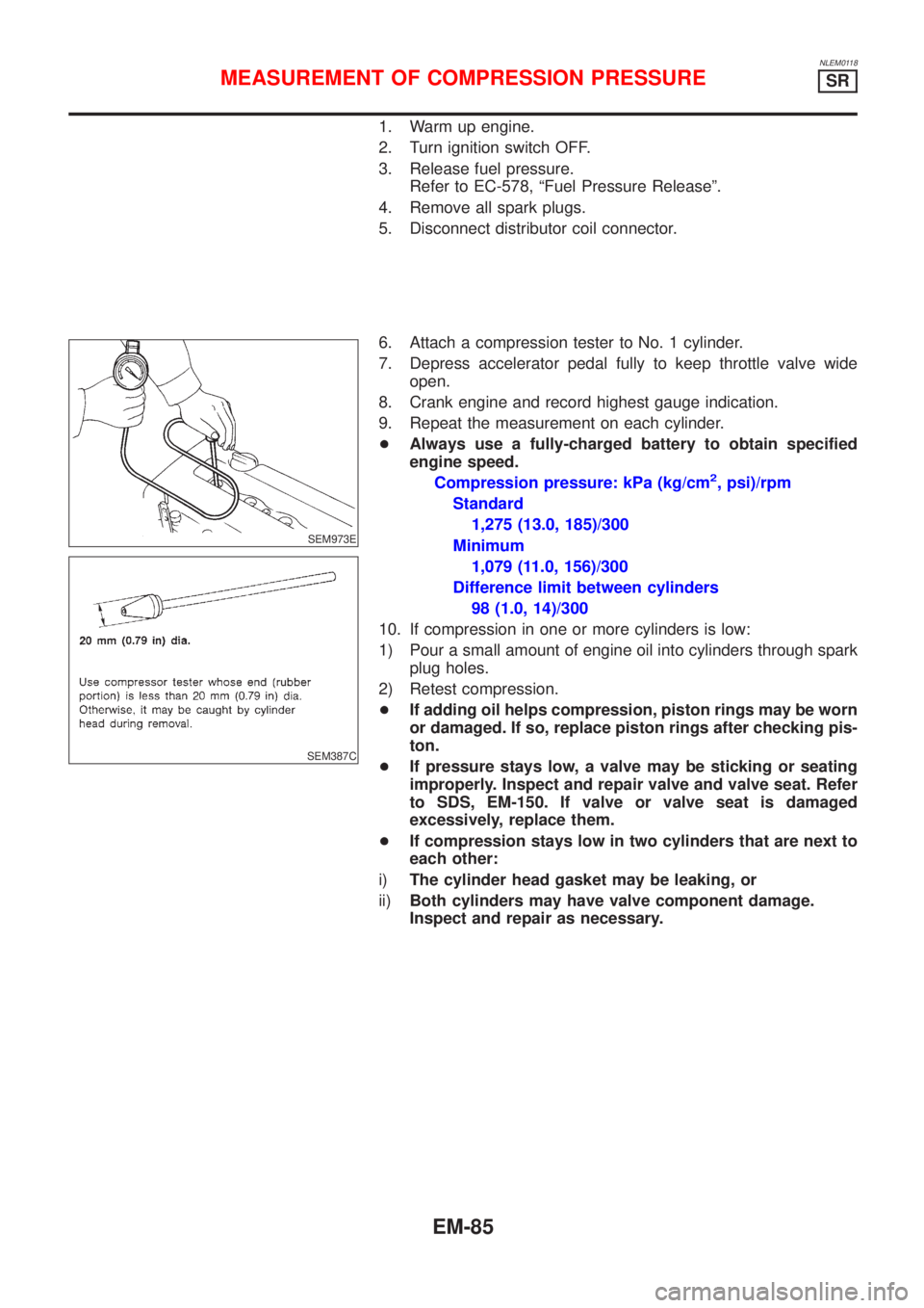
6. Attach a compression tester to No. 1 cylinder.
7. Depress accelerator pedal fully to keep throttle valve wide
open.
8. Crank engine and record highest gauge indication.
9. Repeat the measurement on each cylinder.
+Always use a fully-charged battery to obtain specified
engine speed.
Compression pressure: kPa (kg/cm
2, psi)/rpm
Standard
1,275 (13.0, 185)/300
Minimum
1,079 (11.0, 156)/300
Difference limit between cylinders
98 (1.0, 14)/300
10. If compression in one or more cylinders is low:
1) Pour a small amount of engine oil into cylinders through spark
plug holes.
2) Retest compression.
+If adding oil helps compression, piston rings may be worn
or damaged. If so, replace piston rings after checking pis-
ton.
+If pressure stays low, a valve may be sticking or seating
improperly. Inspect and repair valve and valve seat. Refer
to SDS, EM-150. If valve or valve seat is damaged
excessively, replace them.
+If compression stays low in two cylinders that are next to
each other:
i)The cylinder head gasket may be leaking, or
ii)Both cylinders may have valve component damage.
Inspect and repair as necessary.
MEASUREMENT OF COMPRESSION PRESSURESR
EM-85
Page 2388 of 3051
crankshaft position sensor (OBD) from the assembly.
+Always be extra careful not to damage edge of crankshaft
position sensor (OBD) or ring gear teeth.
SEM174D
REMOVALNLEM0137S011. Remove engine under covers and engine side cover.
2. Drain coolant from both cylinder block and radiator. Refer to
LC-38, ªChanging Engine Coolantº.
3. Drain engine oil.
4. Remove air cleaner assembly and duct.
5. Remove the battery and battery tray.
6. Disconnect the following:
+Vacuum hoses
+Heater hoses
+A/T cooler hoses
+Power steering hoses
+Fuel lines
+Wires
+Harnesses and connectors
+Throttle cable
7. Remove the cooling fans, radiator and reservoir tank.
8. Remove front LH and RH wheels and drive shafts. Refer to
AX-10, ªDrive Shaftº.
9. Remove front exhaust pipe.
10. Remove starter and intake manifold support.
11. Remove the drive belts.
12. Remove power steering oil pump and A/C compressor.
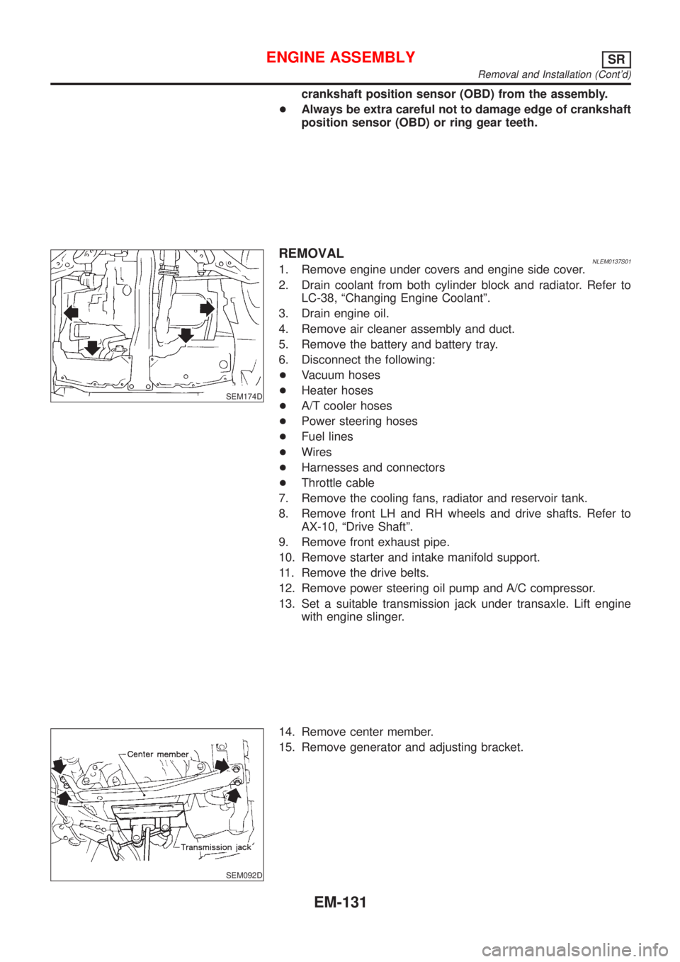
13. Set a suitable transmission jack under transaxle. Lift engine
with engine slinger.
SEM092D
14. Remove center member.
15. Remove generator and adjusting bracket.
ENGINE ASSEMBLYSR
Removal and Installation (Cont'd)
EM-131
Page 2476 of 3051
crankshaft position sensor (TDC sensor) from the assem-
bly.
+Always pay extra attention not to damage edge of crank-
shaft position sensor (TDC sensor) or ring gear teeth.
REMOVALNLEM0069S011. Remove engine undercover, and hood for hoisting.
2. Drain coolant from both cylinder block and radiator. Refer to
LC-59, ªChanging Engine Coolantº.
3. Remove the following parts:
+Battery
+RH and LH front wheels
+RH and LH splash covers (combined with undercover)
+Auxiliary belts
+Alternator
+Alternator brackets
+Radiator and cooling fan
+Engine cover
+Air ducts and air cleaner case
LH side of engine room:
4. Disconnect all harnesses and grounds that are connected to
components on vehicle.
5. Disconnect vacuum hose on vacuum pump side.
6. Disconnect fuel feed and fuel return hoses on engine side.
+Immediately put blind plugs into the openings to prevent
fuel from flowing out.
7. Disconnect heater hose. Plug opening of hose to prevent cool-
ant from flowing out.
RH side of engine room:
8. Remove air conditioner compressor from brackets and move
it toward vehicle side. Secure compressor on vehicle side with
rope.
Vehicle underside:
9. Remove exhaust front tube.
10. Disconnect two hoses from power steering pump and plug to
stop fluid.
11. Remove M/T control rod and support rod.
12. Remove ABS wheel sensor, and temporarily hang brake cali-
per with rope on vehicle side.
13. Remove RH and LH drive shafts.
SEM499G
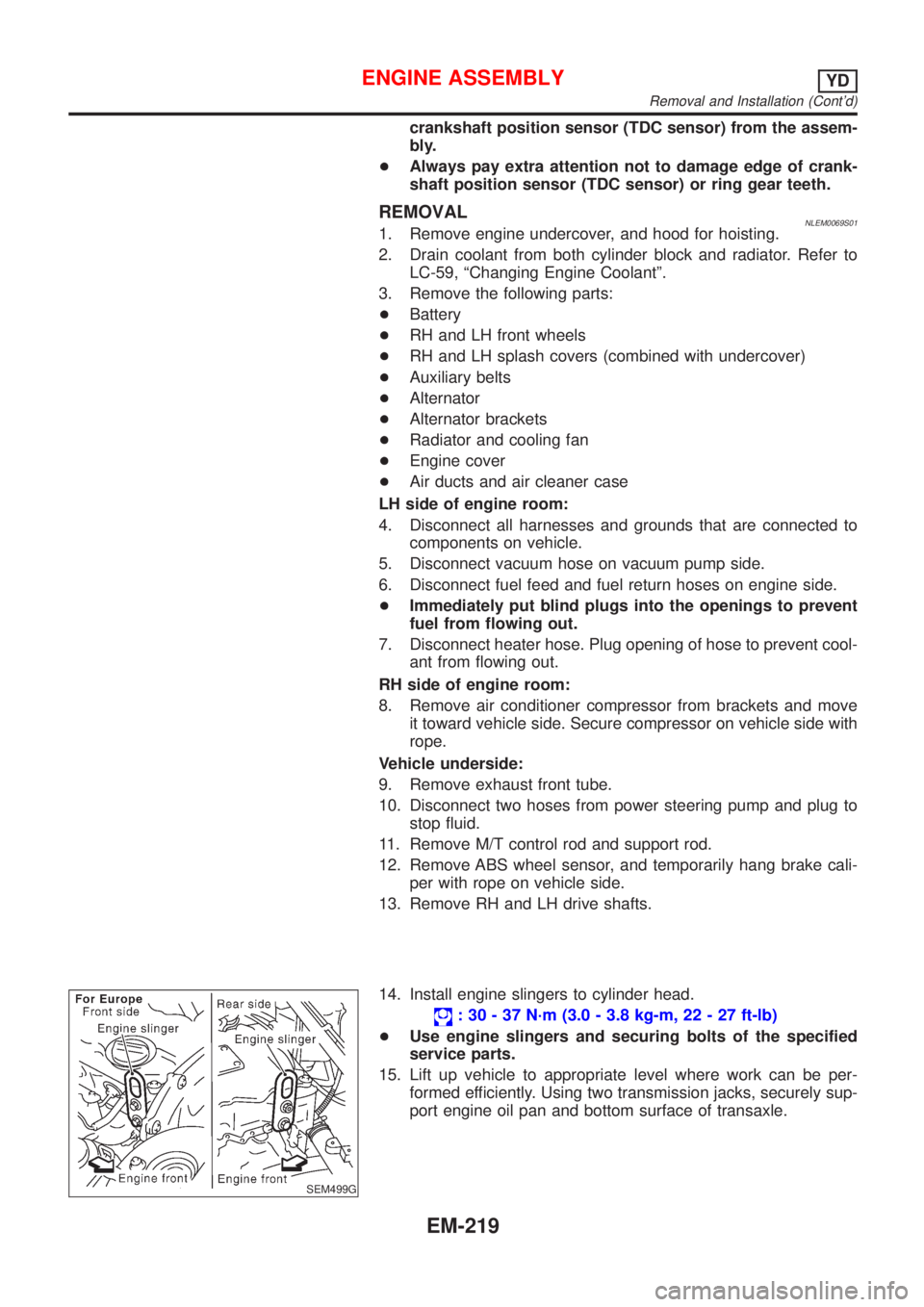
14. Install engine slingers to cylinder head.
: 30 - 37 N´m (3.0 - 3.8 kg-m, 22 - 27 ft-lb)
+Use engine slingers and securing bolts of the specified
service parts.
15. Lift up vehicle to appropriate level where work can be per-
formed efficiently. Using two transmission jacks, securely sup-
port engine oil pan and bottom surface of transaxle.
ENGINE ASSEMBLYYD
Removal and Installation (Cont'd)
EM-219