Page 2515 of 3051
Fuel TankNLFE0006
YFE005
JFE613A
REMOVALNLFE0006S011. Disconnect battery ground cable.
2. Open fuel filler lid and filler cap.
3. Drain fuel from fuel tank.
4. Remove rear seat cushion. Refer to BT-49,“Removal and
Installation”.
5. Remove inspection hole cover under the rear seat.
FUEL SYSTEMQG/SR
Fuel Tank
FE-6
Page 2516 of 3051
SFE639A
SFE640A
6. Disconnect electrical connector.
7. Disconnect the quick connector as follows.
a. Put mating marks on tubes and connectors for correct instal-
lation.
SFE562A
b. Hold the connector while pushing in tabs, and pull out the tube.
CAUTION:
+The tube can be removed when the tabs are completely
depressed. Do not twist it more than necessary.
+Do not use any tools to remove the quick connector.
+Keep the resin tube away from heat. Be especially careful
when welding near the tube.
+Prevent acid liquid such as battery electrolyte etc. from
getting on the resin tube.
+Do not bend or twist the tube during installation and
removal.
SFE650A
8. From rear left area of fuel tank, remove filler hose, vent hose,
and EVAP hose.
CAUTION:
To prevent fuel from flowing out, install a blind cap immedi-
ately after the fuel hose is disconnected.
SFE642A
9. Remove exhaust center tube.
FUEL SYSTEMQG/SR
Fuel Tank (Cont’d)
FE-7
Page 2518 of 3051
Fuel Pump, Fuel Level Sensor Unit and Fuel
Filter
NLFE0007
NFE065
JFE613A
REMOVALNLFE0007S011. Disconnect battery ground cable.
2. Open fuel filler lid and filler cap.
3. Remove rear seat cushion. Refer to BT-49,“Removal and
Installation”.
4. Remove inspection hole cover under the rear seat.
SFE639A
5. Disconnect electrical connector.
6. Disconnect the quick connectors.
+For disconnect of quick connectors, refer to step 7. of“Fuel
Tank Removal”.
FUEL SYSTEMQG/SR
Fuel Pump, Fuel Level Sensor Unit and Fuel Filter
FE-9
Page 2526 of 3051

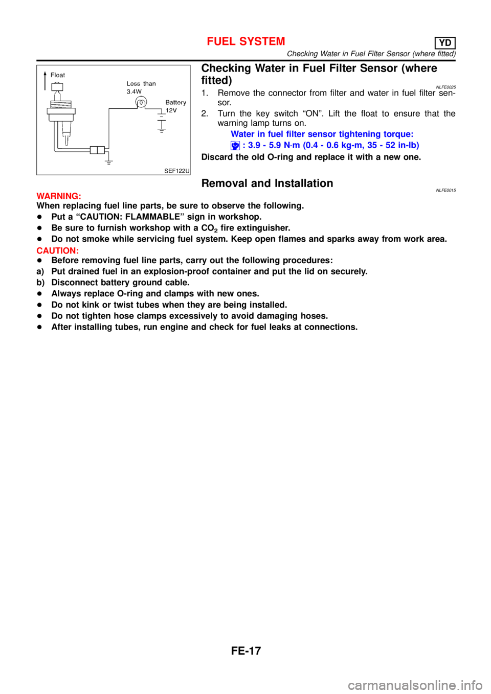
SEF122U
Checking Water in Fuel Filter Sensor (where
fitted)
NLFE00251. Remove the connector from filter and water in fuel filter sen-
sor.
2. Turn the key switch“ON”. Lift the float to ensure that the
warning lamp turns on.
Water in fuel filter sensor tightening torque:
: 3.9 - 5.9 N·m (0.4 - 0.6 kg-m, 35 - 52 in-lb)
Discard the old O-ring and replace it with a new one.
Removal and InstallationNLFE0015WARNING:
When replacing fuel line parts, be sure to observe the following.
+Put a“CAUTION: FLAMMABLE”sign in workshop.
+Be sure to furnish workshop with a CO
2fire extinguisher.
+Do not smoke while servicing fuel system. Keep open flames and sparks away from work area.
CAUTION:
+Before removing fuel line parts, carry out the following procedures:
a) Put drained fuel in an explosion-proof container and put the lid on securely.
b) Disconnect battery ground cable.
+Always replace O-ring and clamps with new ones.
+Do not kink or twist tubes when they are being installed.
+Do not tighten hose clamps excessively to avoid damaging hoses.
+After installing tubes, run engine and check for fuel leaks at connections.
FUEL SYSTEMYD
Checking Water in Fuel Filter Sensor (where fitted)
FE-17
Page 2528 of 3051

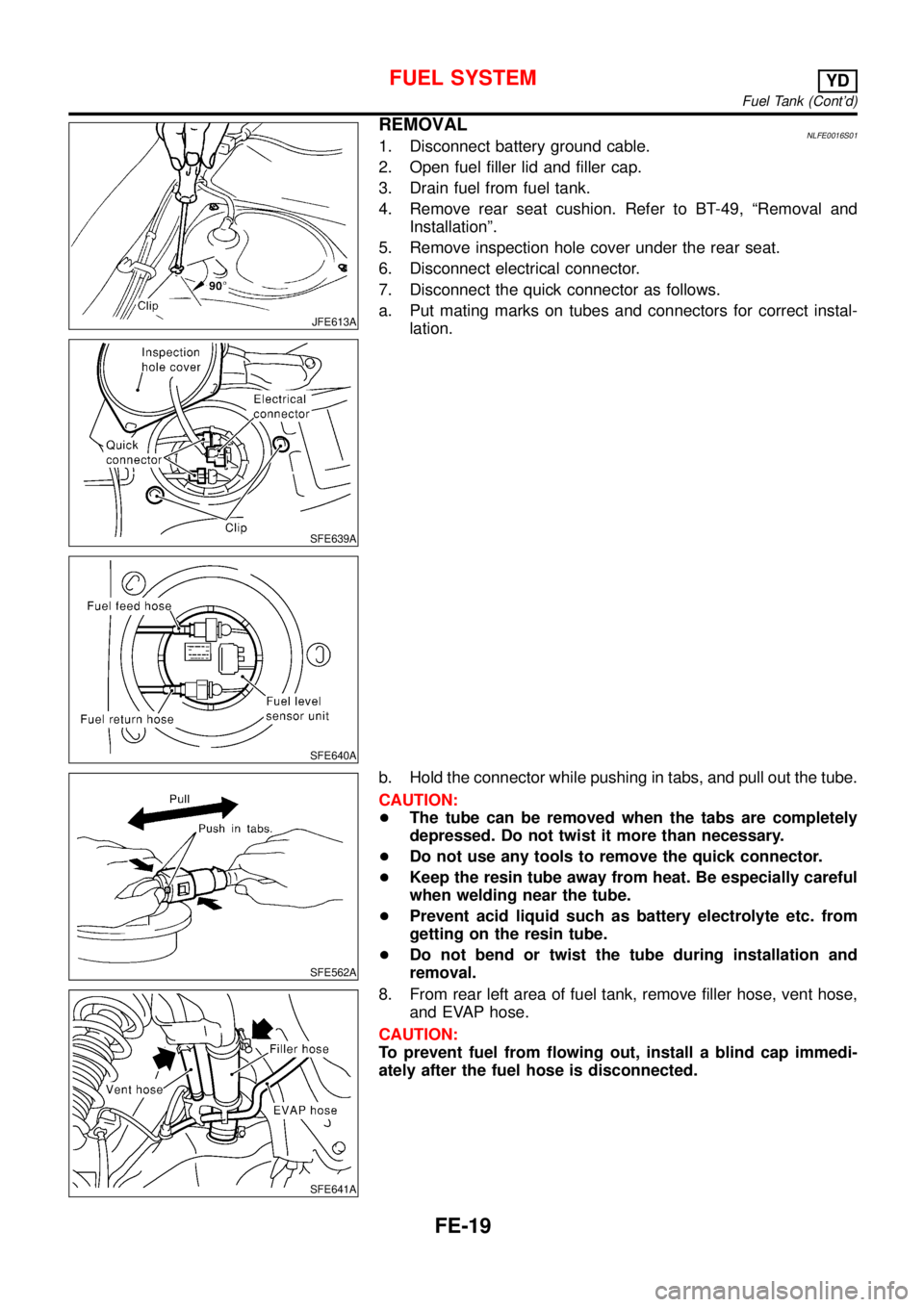
JFE613A
SFE639A
SFE640A
REMOVALNLFE0016S011. Disconnect battery ground cable.
2. Open fuel filler lid and filler cap.
3. Drain fuel from fuel tank.
4. Remove rear seat cushion. Refer to BT-49,“Removal and
Installation”.
5. Remove inspection hole cover under the rear seat.
6. Disconnect electrical connector.
7. Disconnect the quick connector as follows.
a. Put mating marks on tubes and connectors for correct instal-
lation.
SFE562A
b. Hold the connector while pushing in tabs, and pull out the tube.
CAUTION:
+The tube can be removed when the tabs are completely
depressed. Do not twist it more than necessary.
+Do not use any tools to remove the quick connector.
+Keep the resin tube away from heat. Be especially careful
when welding near the tube.
+Prevent acid liquid such as battery electrolyte etc. from
getting on the resin tube.
+Do not bend or twist the tube during installation and
removal.
SFE641A
8. From rear left area of fuel tank, remove filler hose, vent hose,
and EVAP hose.
CAUTION:
To prevent fuel from flowing out, install a blind cap immedi-
ately after the fuel hose is disconnected.
FUEL SYSTEMYD
Fuel Tank (Cont’d)
FE-19
Page 2530 of 3051
Fuel Level Sensor UnitNLFE0032
NFE074
JFE613A
REMOVALNLFE0032S011. Disconnect battery ground cable.
2. Open fuel filler lid and filler cap.
3. Remove rear seat cushion. Refer to BT-49,“Removal and
Installation”.
4. Remove inspection hole cover under the rear seat.
SFE639A
5. Disconnect electrical connector.
6. Disconnect the quick connectors.
+For disconnect of quick connectors, refer to step 7. of“Fuel
Tank Removal”.
FUEL SYSTEMYD
Fuel Level Sensor Unit
FE-21
Page 2540 of 3051

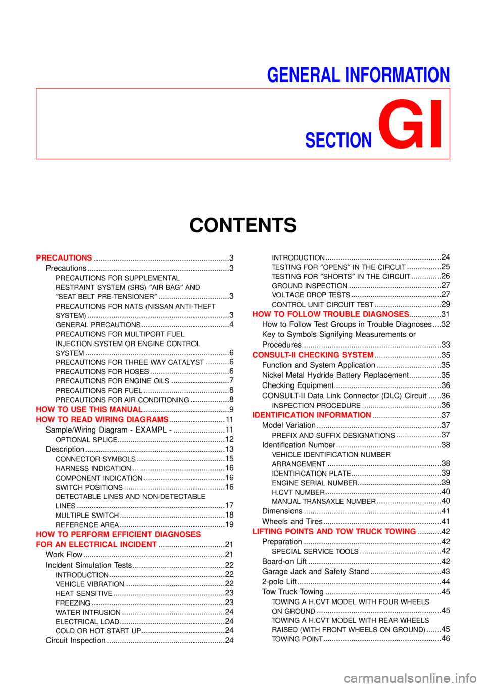
GENERAL INFORMATION
SECTION
GI
CONTENTS
PRECAUTIONS...............................................................3
Precautions ..................................................................3
PRECAUTIONS FOR SUPPLEMENTAL
RESTRAINT SYSTEM (SRS)″AIR BAG″AND
″SEAT BELT PRE-TENSIONER″
.................................3
PRECAUTIONS FOR NATS (NISSAN ANTI-THEFT
SYSTEM)
..................................................................3
GENERAL PRECAUTIONS.........................................4
PRECAUTIONS FOR MULTIPORT FUEL
INJECTION SYSTEM OR ENGINE CONTROL
SYSTEM
...................................................................6
PRECAUTIONS FOR THREE WAY CATALYST...........6
PRECAUTIONS FOR HOSES.....................................6
PRECAUTIONS FOR ENGINE OILS...........................7
PRECAUTIONS FOR FUEL........................................8
PRECAUTIONS FOR AIR CONDITIONING..................8
HOW TO USE THIS MANUAL........................................9
HOW TO READ WIRING DIAGRAMS.......................... 11
Sample/Wiring Diagram - EXAMPL - ........................ 11
OPTIONAL SPLICE..................................................12
Description .................................................................13
CONNECTOR SYMBOLS.........................................15
HARNESS INDICATION...........................................16
COMPONENT INDICATION......................................16
SWITCH POSITIONS...............................................16
DETECTABLE LINES AND NON-DETECTABLE
LINES
.....................................................................17
MULTIPLE SWITCH.................................................18
REFERENCE AREA.................................................19
HOW TO PERFORM EFFICIENT DIAGNOSES
FOR AN ELECTRICAL INCIDENT...............................21
Work Flow ..................................................................21
Incident Simulation Tests ...........................................22
INTRODUCTION......................................................22
VEHICLE VIBRATION..............................................22
HEAT SENSITIVE....................................................23
FREEZING..............................................................23
WATER INTRUSION................................................24
ELECTRICAL LOAD.................................................24
COLD OR HOT START UP.......................................24
Circuit Inspection .......................................................24
INTRODUCTION......................................................24
TESTING FOR″OPENS″IN THE CIRCUIT................25
TESTING FOR″SHORTS″IN THE CIRCUIT..............26
GROUND INSPECTION...........................................27
VOLTAGE DROP TESTS..........................................27
CONTROL UNIT CIRCUIT TEST...............................29
HOW TO FOLLOW TROUBLE DIAGNOSES...............31
How to Follow Test Groups in Trouble Diagnoses ....32
Key to Symbols Signifying Measurements or
Procedures.................................................................33
CONSULT-II CHECKING SYSTEM...............................35
Function and System Application ..............................35
Nickel Metal Hydride Battery Replacement...............35
Checking Equipment..................................................36
CONSULT-II Data Link Connector (DLC) Circuit ......36
INSPECTION PROCEDURE.....................................36
IDENTIFICATION INFORMATION................................37
Model Variation ..........................................................37
PREFIX AND SUFFIX DESIGNATIONS.....................37
Identification Number .................................................38
VEHICLE IDENTIFICATION NUMBER
ARRANGEMENT
.....................................................38
IDENTIFICATION PLATE..........................................39
ENGINE SERIAL NUMBER.......................................39
H.CVT NUMBER......................................................40
MANUAL TRANSAXLE NUMBER..............................40
Dimensions ................................................................41
Wheels and Tires .......................................................41
LIFTING POINTS AND TOW TRUCK TOWING...........42
Preparation ................................................................42
SPECIAL SERVICE TOOLS......................................42
Board-on Lift ..............................................................42
Garage Jack and Safety Stand .................................43
2-pole Lift ...................................................................44
Tow Truck Towing ......................................................45
TOWING A H.CVT MODEL WITH FOUR WHEELS
ON GROUND
..........................................................45
TOWING A H.CVT MODEL WITH REAR WHEELS
RAISED (WITH FRONT WHEELS ON GROUND)
.......45
TOWING POINT.......................................................46
Page 2544 of 3051

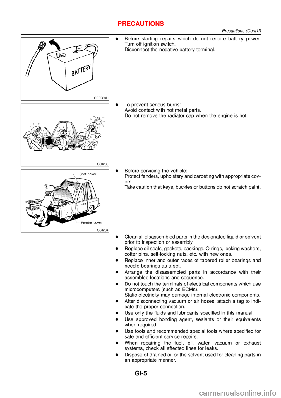
SEF289H
+Before starting repairs which do not require battery power:
Turn off ignition switch.
Disconnect the negative battery terminal.
SGI233
+To prevent serious burns:
Avoid contact with hot metal parts.
Do not remove the radiator cap when the engine is hot.
SGI234
+Before servicing the vehicle:
Protect fenders, upholstery and carpeting with appropriate cov-
ers.
Take caution that keys, buckles or buttons do not scratch paint.
+Clean all disassembled parts in the designated liquid or solvent
prior to inspection or assembly.
+Replace oil seals, gaskets, packings, O-rings, locking washers,
cotter pins, self-locking nuts, etc. with new ones.
+Replace inner and outer races of tapered roller bearings and
needle bearings as a set.
+Arrange the disassembled parts in accordance with their
assembled locations and sequence.
+Do not touch the terminals of electrical components which use
microcomputers (such as ECMs).
Static electricity may damage internal electronic components.
+After disconnecting vacuum or air hoses, attach a tag to indi-
cate the proper connection.
+Use only the fluids and lubricants specified in this manual.
+Use approved bonding agent, sealants or their equivalents
when required.
+Use tools and recommended special tools where specified for
safe and efficient service repairs.
+When repairing the fuel, oil, water, vacuum or exhaust
systems, check all affected lines for leaks.
+Dispose of drained oil or the solvent used for cleaning parts in
an appropriate manner.
PRECAUTIONS
Precautions (Cont’d)
GI-5