2001 NISSAN ALMERA TINO battery
[x] Cancel search: batteryPage 1940 of 3051
carried out. Subsequently, when the repaired audio unit is delivered to the final user again, it will be in the
ªNEWº state as to enable re-linking the audio unit to the vehicle's immobiliser system. As a result of the above,
repair of the audio unit can only be done by an authorized Clarion representative.
Service instruction
Item Radio linked with IMMU and/or SECU
Battery disconnection No additional action required
Radio needs repair Repair needs to be done by authorised representative of radio manufacturer since radio
cannot be operated unless it is reset to NEW state, using special decoding equipment
Replacement of radio by new part Radio is delivered in NEW state. If possible, the radio will automatically link up with the
immobiliser system. If this appears not possible, CATS code needs to be manually input
Transferring radio to another vehicle /
replacement of radio by an ªoldº partRadio needs to be reset to NEW state by authorised representative of radio manufacturer
Replacement of IMMU by new part Radio will request for CATS code input prior to establishing the link with the IMMU
Replacement of IMMU by old part If a radio code has already been stored in memory of the IMMU, the radio cannot be
linked to it. After switching on the radio, it will display ªSECUREº after 1 minute. Operation
can only be established after resetting the ratio by an authorised representative of radio
manufacturer
No communication from IMMU to
radioRadio will display ªSECUREº after 180 attempts to communicate with IMMU. Further use
of radio impossible until communication is established again, or after radio is reset by
authorised representative of (radio) manufacturer
CATS code input procedure
1. Radio displays ªCODE INº after the power is switched ON.
2. Enter CATS code (4±digits) by pressing the preset buttons (using 1 to 4).
Press the preset buttons for the necessary amount of times for the number of each digits.
e.g. CATS code is ª5432º
Press No. 1 preset button for 5 times
Press No. 2 preset button for 4 times
Press No. 3 preset button for 3 times
Press No. 4 preset button for 2 times
3. Press the
button.
4. If the code is OK, the radio will power ON.
If the code is NG, the radio will be locked up as below. After the lock up, the radio will display ªCODE INº
again.
1st to 3rd attempt: The radio will be locked for 10 seconds after each attempt
4th to 20th attempt: The radio will be locked for 60 minutes after each attempt
Over 20th attempt: The radio will be locked completely
SPEED DEPENDENT VOLUME CONTROLNLEL0497S02DescriptionNLEL0497S0201If activated, the radio output volume will be automatically adjusted to compensate for increasing driving noises
at higher driving speeds.
The radio receives a speed signal from the vehicle speed sensor (VSS) and selects the output volume.
PERSONAL AUDIO SETTINGSNLEL0497S03DescriptionNLEL0497S0301The radio is designed to store several settings (volume, bass, treble, preset stations and level of speed
dependent volume control) with every NATS ignition key used. Up to a maximum of 4 NATS keys can be reg-
istered. During the communication as mentioned under ªNATS audio linkº, the radio will recognize the used
ignition key and select the accompanying settings.
AUDIO
System Description (Cont'd)
EL-209
Page 1961 of 3051
Trouble DiagnosesNLEL0385AUDIO UNITNLEL0385S05
Symptom Possible causes Repair order
Audio unit inoperative (no
digital display and no
sound from speakers).1. 10A fuse
2. Poor audio unit case ground
3. Audio unit1. Check 10A fuse [No. 1, located in fuse block (J/B)].
Turn ignition switch ON and verify that battery posi-
tive voltage is present at terminal 3 of audio unit.
2. Check audio unit case ground.
3. Remove audio unit for repair.
Audio unit presets are lost
when ignition switch is
turned OFF.1. 15A fuse
2. Audio unit1. Check 15A fuse and verify that battery positive volt-
age is present at terminal 9 of audio unit.
2. Remove audio unit for repair.
Individual rear speaker is
noisy or inoperative.1. Each speaker
2. Output circuit to each speaker1. Check speaker.
2. Check the output circuits to each speaker
+between audio unit and speaker amp.
+between speaker amp. and each speaker.
AM/FM stations are weak
or noisy.1. Roof antenna
2. Audio unit ground
3. Audio unit1. Check roof antenna.
2. Check audio unit ground condition.
3. Remove audio unit for repair.
Audio unit generates noise
in AM and FM modes with
engine running.1. Poor audio unit ground
2. Loose or missing ground bonding straps
3. Ignition condenser or rear window
defogger noise suppressor condenser
4. Ignition coil or secondary wiring
5. Audio unit1. Check audio unit ground.
2. Check ground bonding straps.
3. Replace ignition condenser or rear window defogger
noise suppressor condenser.
4. Check ignition coil and secondary wiring.
5. Remove audio unit for repair.
Audio unit generates noise
in AM and FM modes with
accessories on (switch
pops and motor noise).1. Poor audio unit ground
2. Antenna
3. Accessory ground
4. Faulty accessory1. Check audio unit ground.
2. Check antenna.
3. Check accessory ground.
4. Replace accessory.
CD AUTOCHANGERNLEL0385S06Testing Magazines and DiscsNLEL0385S06011. Confirm discs are installed correctly into the magazine (not upside down).
2. Visually inspect/compare the customer's discs with each other and other discs.
Identify any of the following conditions:
+Discs with a large outside diameter. [Normal size is 120 mm (4.72 in).]
+Discs with rough or lipped edges.
+Discs with excessive thickness [Normal size is 1.2 mm (0.047 in).]
+Discs with scratches, abrasions, or pits on the surface.
+Discs with grease/oil, fingerprints, foreign material.
+Discs are warped due to excessive heat exposure.
3. Slide/place the discs in and out of the various magazine positions.
Identify any discs and/or positions that require additional force for placement/ejection. If interference
(sticking, excessive tensions) is found, replace the magazine or the discs.
NOTE:
+Discs which are marginally out of specification (ex. dirty, scratched and so on) may play correctly
on a home stereo.
However, when used in the automotive environment skipping may occur due to the added vehicle
movement and/or vibration due to road conditions. Autochangers should not be replaced when
discs are at fault.
+Use a soft damp cloth to wipe the discs starting from the center outward in radial direction. Never
use chemical cleaning solutions to clean the discs.
Locking CD Changer Unit MechanismNLEL0385S0602CAUTION:
+Prior to removing a malfunctioning CD changer unit that will be shipped for repair, the changer
mechanism MUST BE LOCKED to prevent the mechanism from being damaged during shipping.
AUDIO
Trouble Diagnoses
EL-230
Page 1962 of 3051
+If a CD is jammed or unable to be removed from the unit, do NOT lock the changer mechanism. If
the unit is to be shipped for repair, carefully package the unit to prevent vibration and shock.
1. Eject and remove any CDs from the CD changer unit.
2. Turn ignition switch OFF. Wait until CD changer unit display is off and mechanism stops moving (mecha-
nism sound stops).
3. Press any one of the disc selection buttons once. When a display shows on the CD changer unit, press
the same disc selection button again within 5 seconds.
+The changer mechanism will lock itself within 10 seconds.
4. After mechanism stops moving (mechanism sound stops), disconnect the CD changer unit connectors.
5. Remove CD changer unit.
NOTE:
+Do not disconnect battery cable (any power supply) until completion of mechanism movement.
+If the ignition switch is turned ON or ACC position after the damper locking, it will be unlocked automati-
cally and the damper locking procedure will be required again.
After installing a new or remanufactured CD changer unit, switching the CD changer unit ON will automati-
cally unlock the mechanism. A special unlocking procedure is not required.
AUDIO
Trouble Diagnoses (Cont'd)
EL-231
Page 1971 of 3051
Trouble DiagnosesNLEL0225
Symptom Possible cause Repair order
Power sunroof cannot be operated
using any switch.1. 10A fuse, 30A fusible link and
M4 circuit breaker
2. Sunroof motor ground circuit
3. Sunroof switch
4. Sunroof switch circuit
5. Sunroof motor1. Check 10A fuse [No. 10, located in fuse block
(J/B)], 30A fusible link and M4 circuit breaker. Verify
battery positive voltage is present at terminal 5 of
sunroof motor. And then turn ignition switch ªONº
and verify battery positive voltage is present at ter-
minal 5 of sunroof switch.
2. Check sunroof motor ground circuit.
3. Check sunroof switch.
4. Check harness between sunroof switch and sunroof
motor.
5. Check sunroof motor.
Power sunroof cannot be operated
using one of the sunroof switches.1. Sunroof switch
2. Sunroof switch circuit1. Check sunroof switch.
2. Check the harness between sunroof motor and sun-
roof switch.
POWER SUNROOF
Trouble Diagnoses
EL-240
Page 1987 of 3051
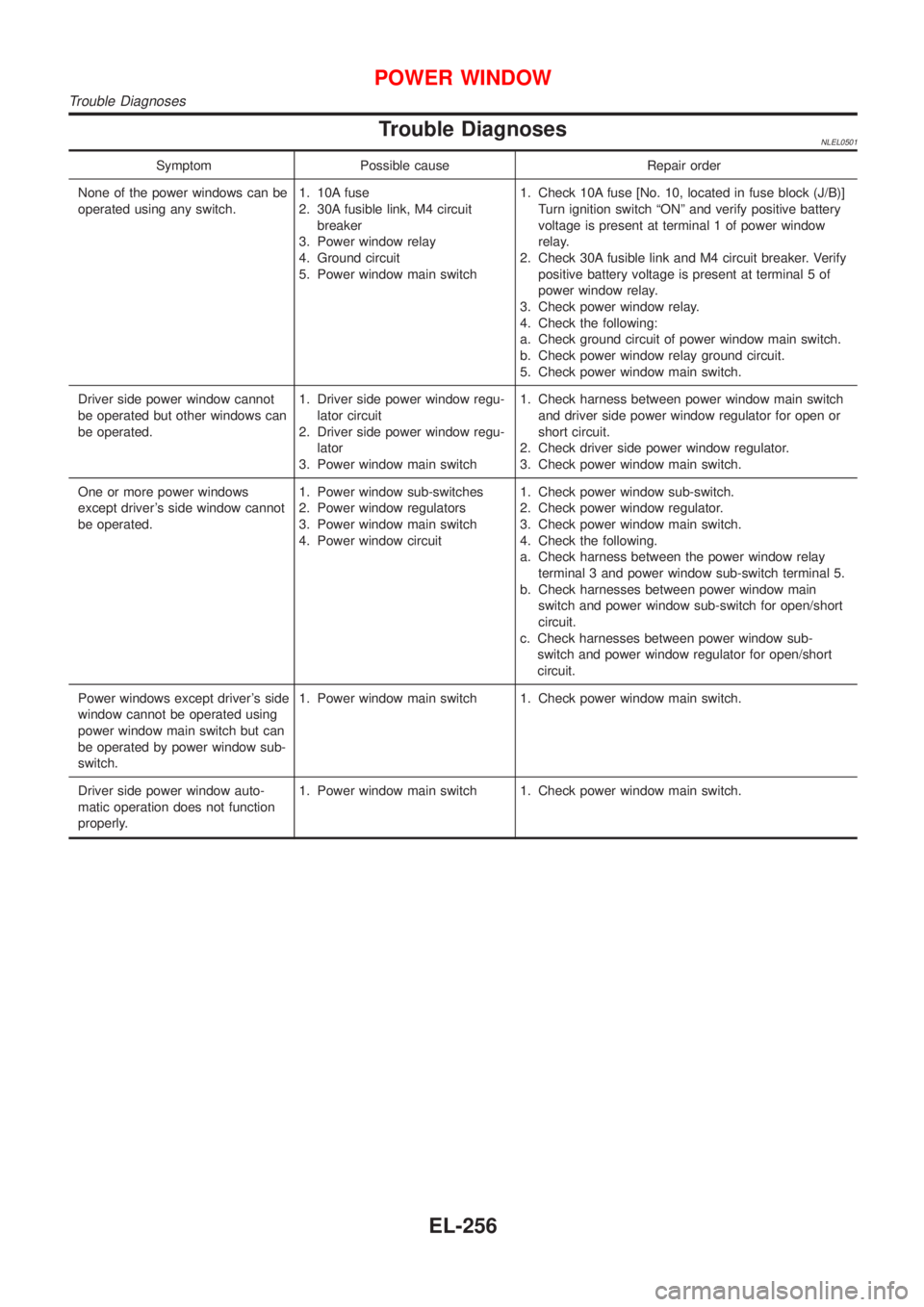
Trouble DiagnosesNLEL0501
Symptom Possible cause Repair order
None of the power windows can be
operated using any switch.1. 10A fuse
2. 30A fusible link, M4 circuit
breaker
3. Power window relay
4. Ground circuit
5. Power window main switch1. Check 10A fuse [No. 10, located in fuse block (J/B)]
Turn ignition switch ªONº and verify positive battery
voltage is present at terminal 1 of power window
relay.
2. Check 30A fusible link and M4 circuit breaker. Verify
positive battery voltage is present at terminal 5 of
power window relay.
3. Check power window relay.
4. Check the following:
a. Check ground circuit of power window main switch.
b. Check power window relay ground circuit.
5. Check power window main switch.
Driver side power window cannot
be operated but other windows can
be operated.1. Driver side power window regu-
lator circuit
2. Driver side power window regu-
lator
3. Power window main switch1. Check harness between power window main switch
and driver side power window regulator for open or
short circuit.
2. Check driver side power window regulator.
3. Check power window main switch.
One or more power windows
except driver's side window cannot
be operated.1. Power window sub-switches
2. Power window regulators
3. Power window main switch
4. Power window circuit1. Check power window sub-switch.
2. Check power window regulator.
3. Check power window main switch.
4. Check the following.
a. Check harness between the power window relay
terminal 3 and power window sub-switch terminal 5.
b. Check harnesses between power window main
switch and power window sub-switch for open/short
circuit.
c. Check harnesses between power window sub-
switch and power window regulator for open/short
circuit.
Power windows except driver's side
window cannot be operated using
power window main switch but can
be operated by power window sub-
switch.1. Power window main switch 1. Check power window main switch.
Driver side power window auto-
matic operation does not function
properly.1. Power window main switch 1. Check power window main switch.
POWER WINDOW
Trouble Diagnoses
EL-256
Page 2013 of 3051
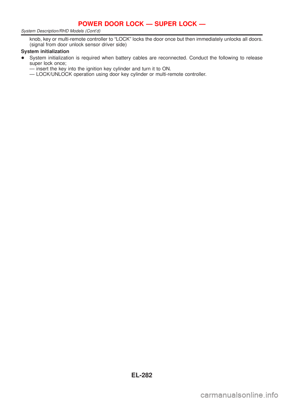
knob, key or multi-remote controller to ªLOCKº locks the door once but then immediately unlocks all doors.
(signal from door unlock sensor driver side)
System initialization
+System initialization is required when battery cables are reconnected. Conduct the following to release
super lock once;
Ð insert the key into the ignition key cylinder and turn it to ON.
Ð LOCK/UNLOCK operation using door key cylinder or multi-remote controller.
POWER DOOR LOCK Ð SUPER LOCK Ð
System Description/RHD Models (Cont'd)
EL-282
Page 2042 of 3051
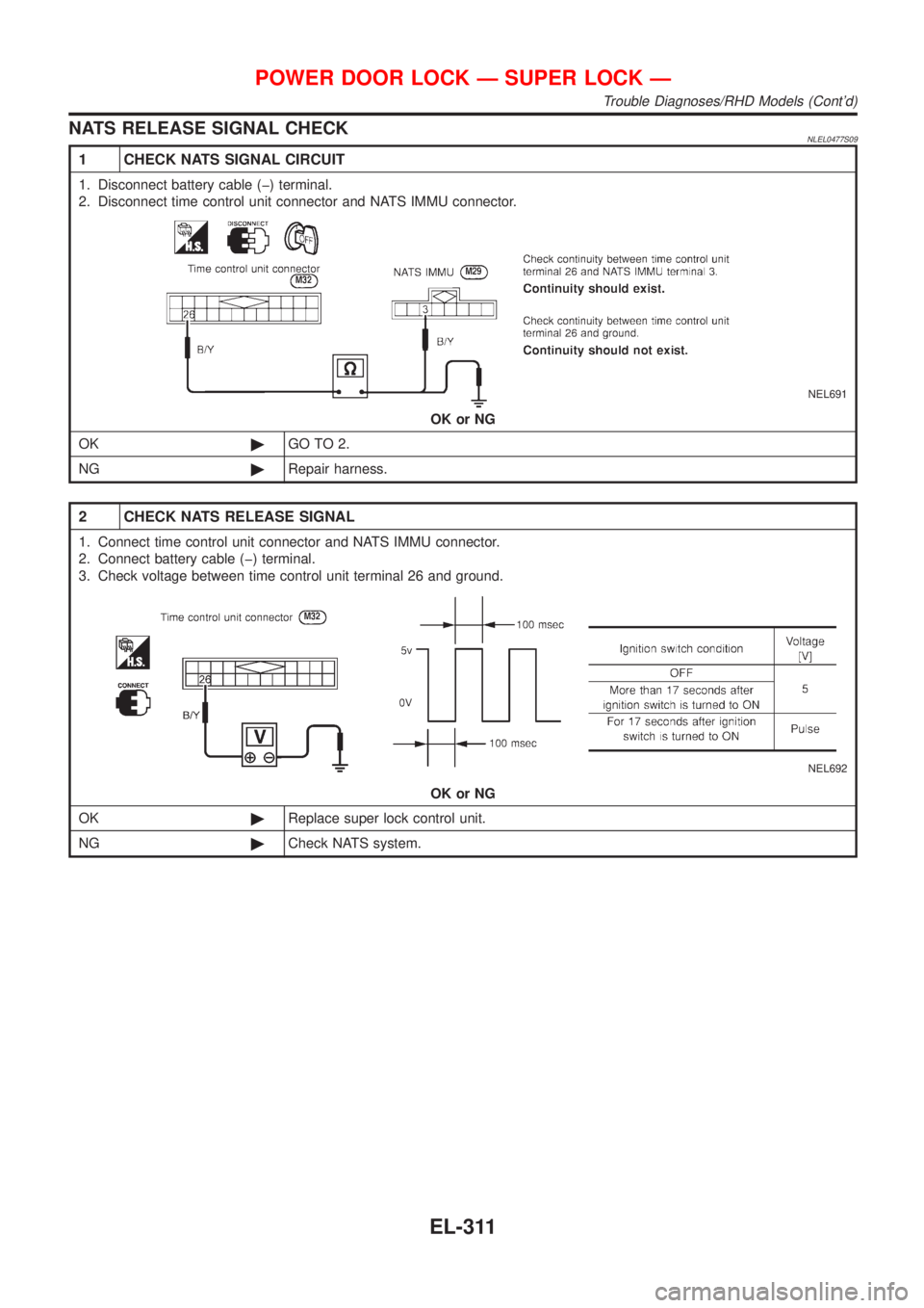
NATS RELEASE SIGNAL CHECKNLEL0477S09
1 CHECK NATS SIGNAL CIRCUIT
1. Disconnect battery cable (þ) terminal.
2. Disconnect time control unit connector and NATS IMMU connector.
NEL691
OK or NG
OK©GO TO 2.
NG©Repair harness.
2 CHECK NATS RELEASE SIGNAL
1. Connect time control unit connector and NATS IMMU connector.
2. Connect battery cable (þ) terminal.
3. Check voltage between time control unit terminal 26 and ground.
NEL692
OK or NG
OK©Replace super lock control unit.
NG©Check NATS system.
POWER DOOR LOCK Ð SUPER LOCK Ð
Trouble Diagnoses/RHD Models (Cont'd)
EL-311
Page 2044 of 3051
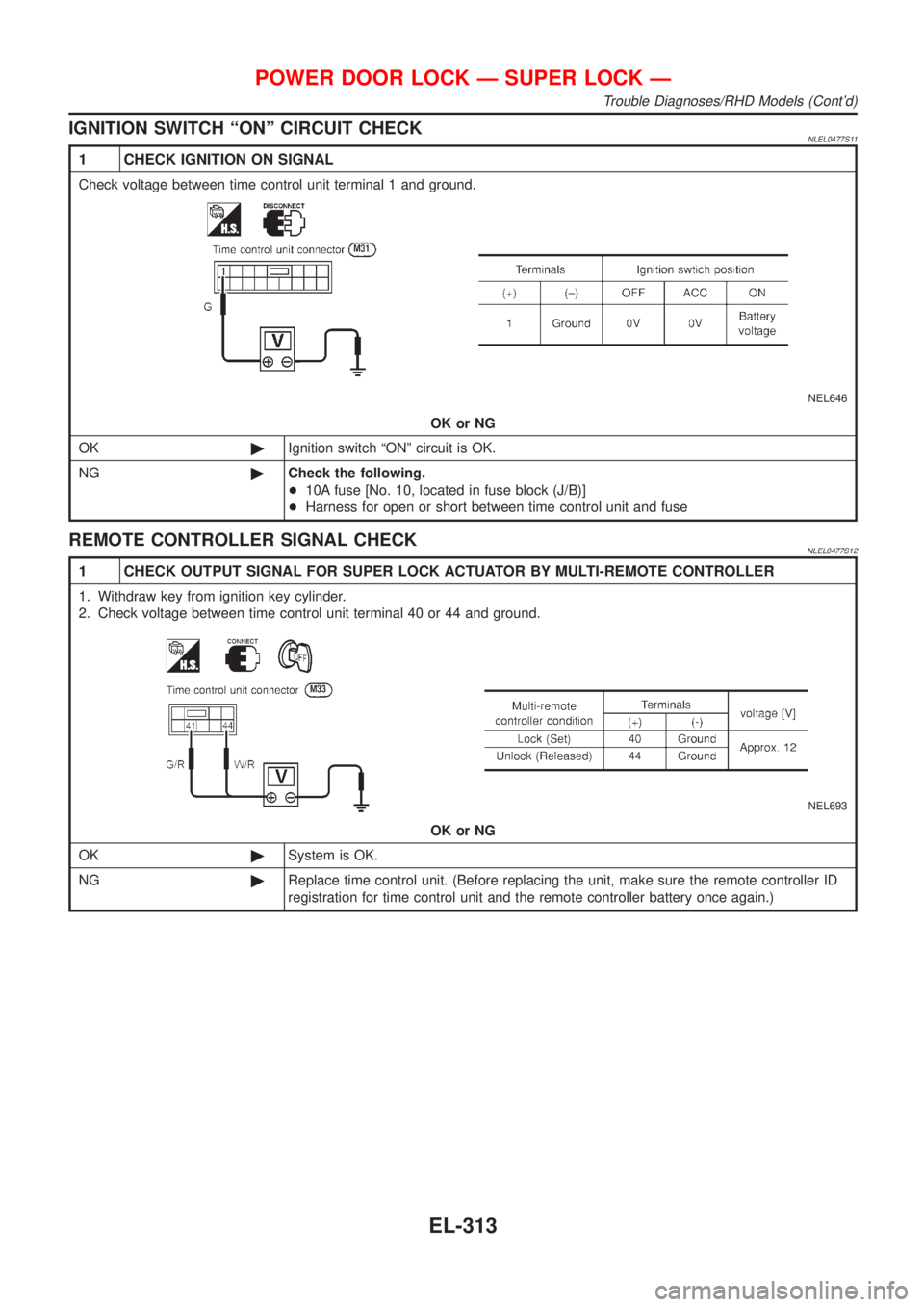
IGNITION SWITCH ªONº CIRCUIT CHECKNLEL0477S11
1 CHECK IGNITION ON SIGNAL
Check voltage between time control unit terminal 1 and ground.
NEL646
OK or NG
OK©Ignition switch ªONº circuit is OK.
NG©Check the following.
+10A fuse [No. 10, located in fuse block (J/B)]
+Harness for open or short between time control unit and fuse
REMOTE CONTROLLER SIGNAL CHECKNLEL0477S12
1 CHECK OUTPUT SIGNAL FOR SUPER LOCK ACTUATOR BY MULTI-REMOTE CONTROLLER
1. Withdraw key from ignition key cylinder.
2. Check voltage between time control unit terminal 40 or 44 and ground.
NEL693
OK or NG
OK©System is OK.
NG©Replace time control unit. (Before replacing the unit, make sure the remote controller ID
registration for time control unit and the remote controller battery once again.)
POWER DOOR LOCK Ð SUPER LOCK Ð
Trouble Diagnoses/RHD Models (Cont'd)
EL-313