Page 1641 of 3051
6 CHECK COOLING FAN RELAYS-2 AND -4
Check continuity between cooling fan relay-2, -3 terminals 3 and 4, 3 and 5 under the following conditions.
SEF900Y
OK or NG
OK©GO TO 7.
NG©Replace cooling fan relays.
7 CHECK COOLING FAN RELAY-3
Check continuity between cooling fan relay-3 terminals 3 and 5 under the following conditions.
SEF901Y
OK or NG
OK©GO TO 8.
NG©Replace cooling fan relay.
8 CHECK COOLING FAN MOTORS
Supply battery voltage between the following terminals and check operation.
SEF902YA
OK or NG
OK©GO TO 9.
NG©Replace cooling fan motors.
DTC P1217 OVER HEATYD22DDTI
Diagnostic Procedure (Cont'd)
EC-1216
Page 1680 of 3051
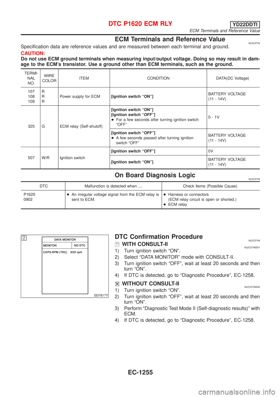
ECM Terminals and Reference ValueNLEC0744Specification data are reference values and are measured between each terminal and ground.
CAUTION:
Do not use ECM ground terminals when measuring input/output voltage. Doing so may result in dam-
age to the ECM's transistor. Use a ground other than ECM terminals, such as the ground.
TERMI-
NAL
NO.WIRE
COLORITEM CONDITION DATA(DC Voltage)
107
108
109R
R
RPower supply for ECM[Ignition switch ªONº]BATTERY VOLTAGE
(11 - 14V)
325 G ECM relay (Self-shutoff)[Ignition switch ªONº]
[Ignition switch ªOFFº]
+For a few seconds after turning ignition switch
ªOFFº0-1V
[Ignition switch ªOFFº]
+A few seconds passed after turning ignition
switch ªOFFºBATTERY VOLTAGE
(11 - 14V)
507 W/R Ignition switch[Ignition switch ªOFFº]0V
[Ignition switch ªONº]BATTERY VOLTAGE
(11 - 14V)
On Board Diagnosis LogicNLEC0745
DTC Malfunction is detected when .... Check Items (Possible Cause)
P1620
0902+An irregular voltage signal from the ECM relay is
sent to ECM.+Harness or connectors
(ECM relay circuit is open or shorted.)
+ECM relay
SEF817Y
DTC Confirmation ProcedureNLEC0746WITH CONSULT-IINLEC0746S011) Turn ignition switch ªONº.
2) Select ªDATA MONITORº mode with CONSULT-II.
3) Turn ignition switch ªOFFº, wait at least 20 seconds and then
turn ªONº.
4) If DTC is detected, go to ªDiagnostic Procedureº, EC-1258.
WITHOUT CONSULT-IINLEC0746S021) Turn ignition switch ªONº.
2) Turn ignition switch ªOFFº, wait at least 20 seconds and then
turn ªONº.
3) Perform ªDiagnostic Test Mode II (Self-diagnostic results)º with
ECM.
4) If DTC is detected, go to ªDiagnostic Procedureº, EC-1258.
DTC P1620 ECM RLYYD22DDTI
ECM Terminals and Reference Value
EC-1255
Page 1683 of 3051
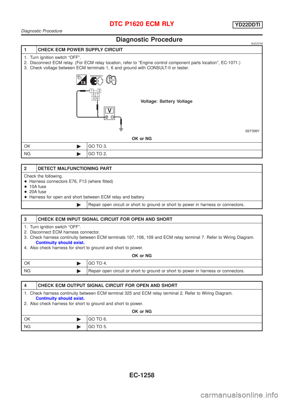
Diagnostic ProcedureNLEC0748
1 CHECK ECM POWER SUPPLY CIRCUIT
1. Turn ignition switch ªOFFº.
2. Disconnect ECM relay. (For ECM relay location, refer to ªEngine control component parts locationº, EC-1071.)
3. Check voltage between ECM terminals 1, 6 and ground with CONSULT-II or tester.
SEF399Y
OK or NG
OK©GO TO 3.
NG©GO TO 2.
2 DETECT MALFUNCTIONING PART
Check the following.
+Harness connectors E76, F13 (where fitted)
+10A fuse
+20A fuse
+Harness for open and short between ECM relay and battery
©Repair open circuit or short to ground or short to power in harness or connectors.
3 CHECK ECM INPUT SIGNAL CIRCUIT FOR OPEN AND SHORT
1. Turn ignition switch ªOFFº.
2. Disconnect ECM harness connector.
3. Check harness continuity between ECM terminals 107, 108, 109 and ECM relay terminal 7. Refer to Wiring Diagram.
Continuity should exist.
4. Also check harness for short to ground and short to power.
OK or NG
OK©GO TO 4.
NG©Repair open circuit or short to ground or short to power in harness or connectors.
4 CHECK ECM OUTPUT SIGNAL CIRCUIT FOR OPEN AND SHORT
1. Check harness continuity between ECM terminal 325 and ECM relay terminal 2. Refer to Wiring Diagram.
Continuity should exist.
2. Also check harness for short to ground and short to power.
OK or NG
OK©GO TO 6.
NG©GO TO 5.
DTC P1620 ECM RLYYD22DDTI
Diagnostic Procedure
EC-1258
Page 1693 of 3051
ECM Terminals and Reference ValueNLEC0761Specification data are reference values and are measured between each terminal and ground.
CAUTION:
Do not use ECM ground terminals when measuring input/output voltage. Doing so may result in dam-
age to the ECM's transistor. Use a ground other than ECM terminals, such as the ground.
TERMI-
NAL
NO.WIRE
COLORITEM CONDITION DATA (DC Voltage)
214 W/B Glow relay Refer to ªSYSTEM DESCRIPTIONº, EC-1267.
508 OR Glow indicator lamp[Ignition switch ªONº]
+Glow indicator lamp is ªONºApproximately 1V
[Ignition switch ªONº]
+Glow indicator lamp is ªOFFºBATTERY VOLTAGE
(11 - 14V)
GLOW CONTROL SYSTEMYD22DDTI
ECM Terminals and Reference Value
EC-1268
Page 1699 of 3051
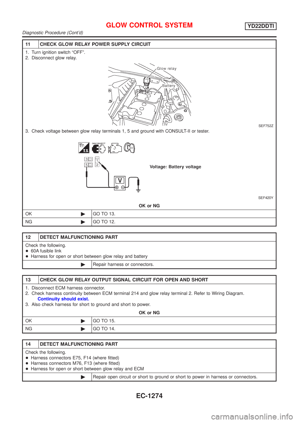
11 CHECK GLOW RELAY POWER SUPPLY CIRCUIT
1. Turn ignition switch ªOFFº.
2. Disconnect glow relay.
SEF752Z
3. Check voltage between glow relay terminals 1, 5 and ground with CONSULT-II or tester.
SEF420Y
OK or NG
OK©GO TO 13.
NG©GO TO 12.
12 DETECT MALFUNCTIONING PART
Check the following.
+60A fusible link
+Harness for open or short between glow relay and battery
©Repair harness or connectors.
13 CHECK GLOW RELAY OUTPUT SIGNAL CIRCUIT FOR OPEN AND SHORT
1. Disconnect ECM harness connector.
2. Check harness continuity between ECM terminal 214 and glow relay terminal 2. Refer to Wiring Diagram.
Continuity should exist.
3. Also check harness for short to ground and short to power.
OK or NG
OK©GO TO 15.
NG©GO TO 14.
14 DETECT MALFUNCTIONING PART
Check the following.
+Harness connectors E75, F14 (where fitted)
+Harness connectors M76, F13 (where fitted)
+Harness for open or short between glow relay and ECM
©Repair open circuit or short to ground or short to power in harness or connectors.
GLOW CONTROL SYSTEMYD22DDTI
Diagnostic Procedure (Cont'd)
EC-1274
Page 1707 of 3051
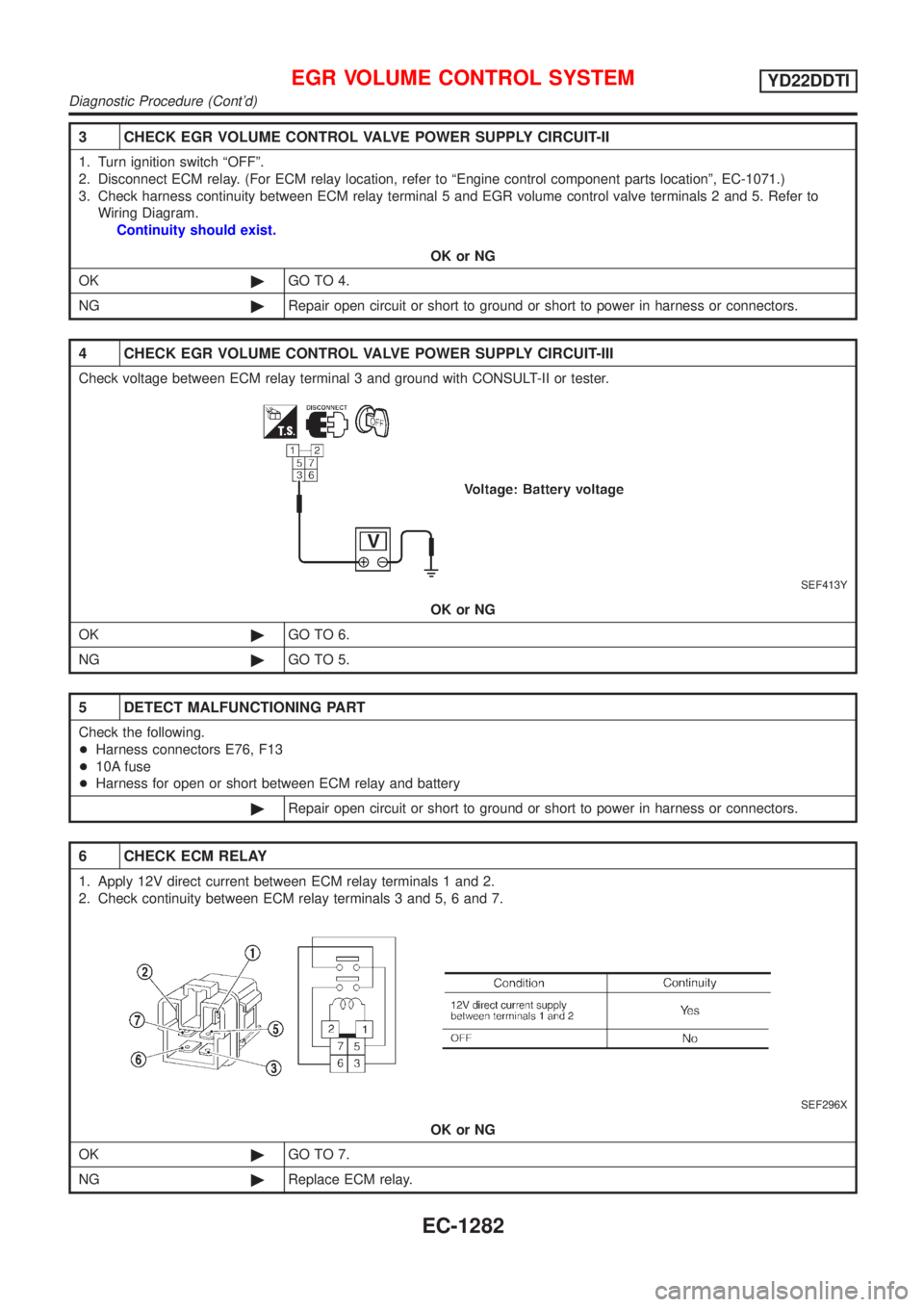
3 CHECK EGR VOLUME CONTROL VALVE POWER SUPPLY CIRCUIT-II
1. Turn ignition switch ªOFFº.
2. Disconnect ECM relay. (For ECM relay location, refer to ªEngine control component parts locationº, EC-1071.)
3. Check harness continuity between ECM relay terminal 5 and EGR volume control valve terminals 2 and 5. Refer to
Wiring Diagram.
Continuity should exist.
OK or NG
OK©GO TO 4.
NG©Repair open circuit or short to ground or short to power in harness or connectors.
4 CHECK EGR VOLUME CONTROL VALVE POWER SUPPLY CIRCUIT-III
Check voltage between ECM relay terminal 3 and ground with CONSULT-II or tester.
SEF413Y
OK or NG
OK©GO TO 6.
NG©GO TO 5.
5 DETECT MALFUNCTIONING PART
Check the following.
+Harness connectors E76, F13
+10A fuse
+Harness for open or short between ECM relay and battery
©Repair open circuit or short to ground or short to power in harness or connectors.
6 CHECK ECM RELAY
1. Apply 12V direct current between ECM relay terminals 1 and 2.
2. Check continuity between ECM relay terminals 3 and 5, 6 and 7.
SEF296X
OK or NG
OK©GO TO 7.
NG©Replace ECM relay.
EGR VOLUME CONTROL SYSTEMYD22DDTI
Diagnostic Procedure (Cont'd)
EC-1282
Page 1711 of 3051
CONSULT-II Reference Value in Data Monitor
Mode
NLEC1267Specification data are reference values.
MONITOR ITEM CONDITION SPECIFICATION
SWRL CONT S/V+Engine: After warming up
+No-loadEngine speed: 1,500 rpm ON
Engine speed: Idle OFF
ECM Terminals and Reference ValueNLEC1268Specification data are reference values and are measured between each terminal and ground.
CAUTION:
Do not use ECM ground terminals when measuring input/output voltage. Doing so may damage the
ECM's transistor. Use a ground other than ECM terminals, such as the ground.
TER-
MINAL
NO.WIRE
COLORITEM CONDITIOND ATA
(DC Voltage)
209 G/WSwirl control valve control
solenoid valve[Engine is running.]
+Warm-up condition
+Engine speed: 1,500 rpm
+No loadApproximately 0.1V
[Engine is running.]
+Idle speedBATTERY VOLTAGE
(11 - 14V)
SWIRL CONTROL VALVE CONTROL SOLENOID VALVEYD22DDTI
CONSULT-II Reference Value in Data Monitor Mode
EC-1286
Page 1722 of 3051
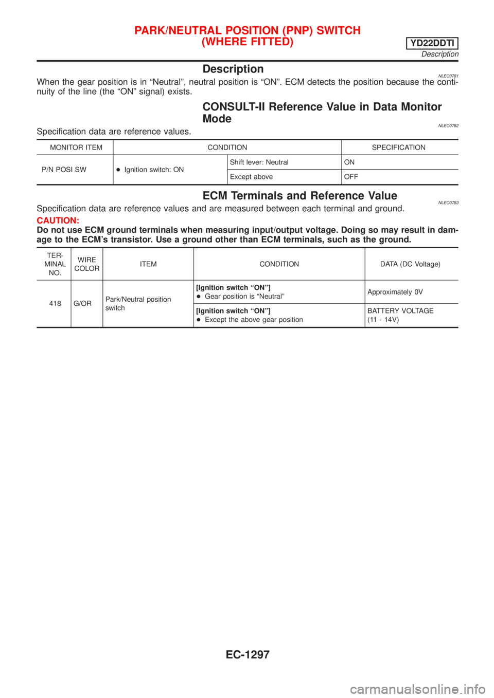
DescriptionNLEC0781When the gear position is in ªNeutralº, neutral position is ªONº. ECM detects the position because the conti-
nuity of the line (the ªONº signal) exists.
CONSULT-II Reference Value in Data Monitor
Mode
NLEC0782Specification data are reference values.
MONITOR ITEM CONDITION SPECIFICATION
P/N POSI SW+Ignition switch: ONShift lever: Neutral ON
Except above OFF
ECM Terminals and Reference ValueNLEC0783Specification data are reference values and are measured between each terminal and ground.
CAUTION:
Do not use ECM ground terminals when measuring input/output voltage. Doing so may result in dam-
age to the ECM's transistor. Use a ground other than ECM terminals, such as the ground.
TER-
MINAL
NO.WIRE
COLORITEM CONDITION DATA (DC Voltage)
418 G/ORPark/Neutral position
switch[Ignition switch ªONº]
+Gear position is ªNeutralºApproximately 0V
[Ignition switch ªONº]
+Except the above gear positionBATTERY VOLTAGE
(11 - 14V)
PARK/NEUTRAL POSITION (PNP) SWITCH
(WHERE FITTED)
YD22DDTI
Description
EC-1297